Settings
Settings

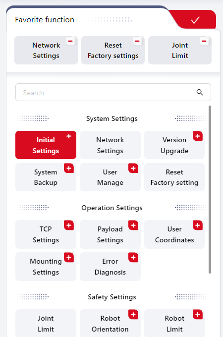
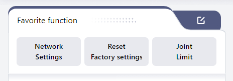
Favorite function
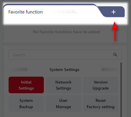
In the Favorite function interface, users can click + to add their most commonly used settings.
The specific steps are as follows:
- Click the red
+in the upper right corner of the desired setting box:
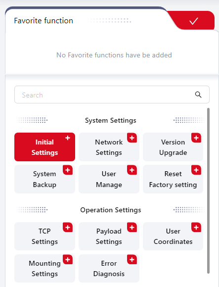
- The selected setting box will then be displayed in the blank area. Click
-to remove any selected items. Click√in the upper right corner to confirm and save.
- After saving, users can directly click the corresponding setting box in
Common functionto jump to the related interface for operation. The settings can also be modified by clicking the icon in the upper right corner.
System Settings
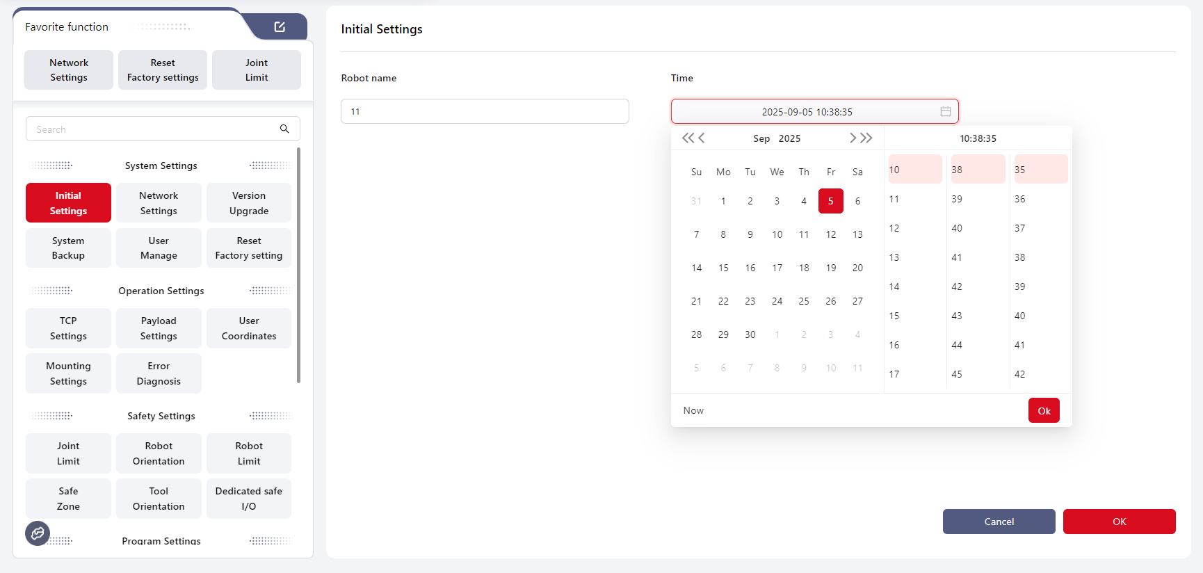
Initial Settings
This interface allows setting the Robot Name and Time.
In Robot Name, enter the desired name, ensuring that the input does not contain special characters other than underscores. Click OK to save and apply.
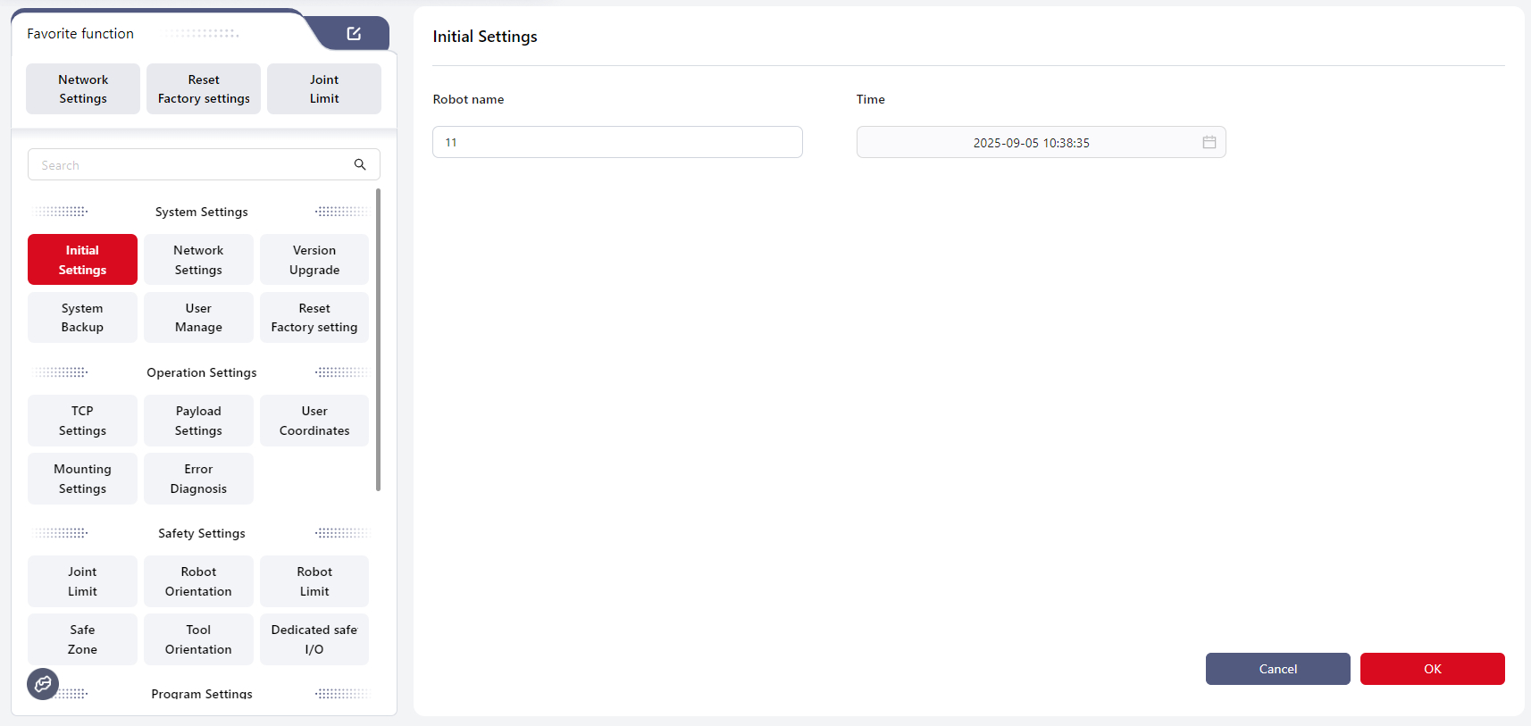
In Time, the system time can be set. Click OK to save and apply.
As shown below, the user can:
- Enter the time directly in the input box;
- Select the time from the calendar;
- Click
Nowto set the current time.
Network Settings
This interface allows selecting how the robot obtains its IP address, with options for Automatically Obtain IP Address or Use the Following IP Address .
By default, the robot is set to obtain its IP address automatically.
If it is necessary to set a static IP for the robot, i.e., "Use the following IP address," ensure that all devices communicating with the robot over the network (including debugging devices) are on the same subnet as the robot.
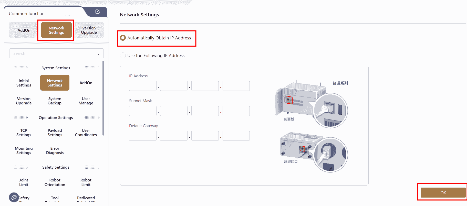
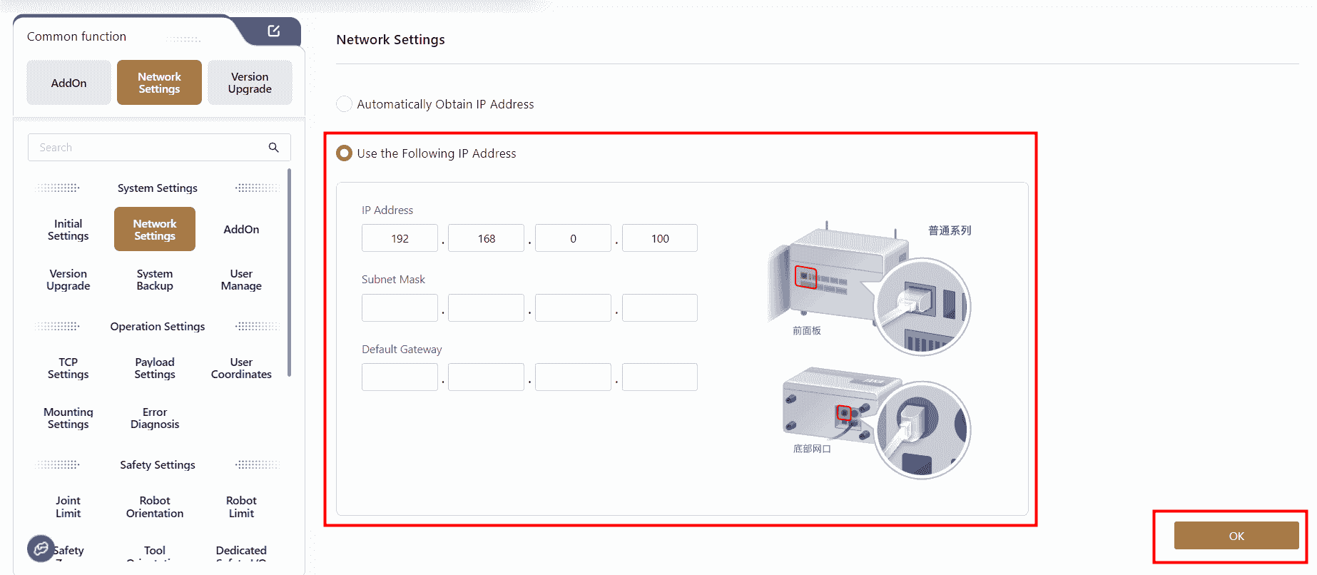
Note:
- Before setting a static IP address for the robot, ensure the robot is powered-off and disabled.
- When setting a static IP, after clicking confirm, the page will prompt a network configuration restart. The connection will be temporarily disconnected.
Note:
For CAB 2.1, custom IP settings only apply to the bottom network port.
For MiniCab, custom IP settings only apply to the LAN2 port.
Version Upgrade
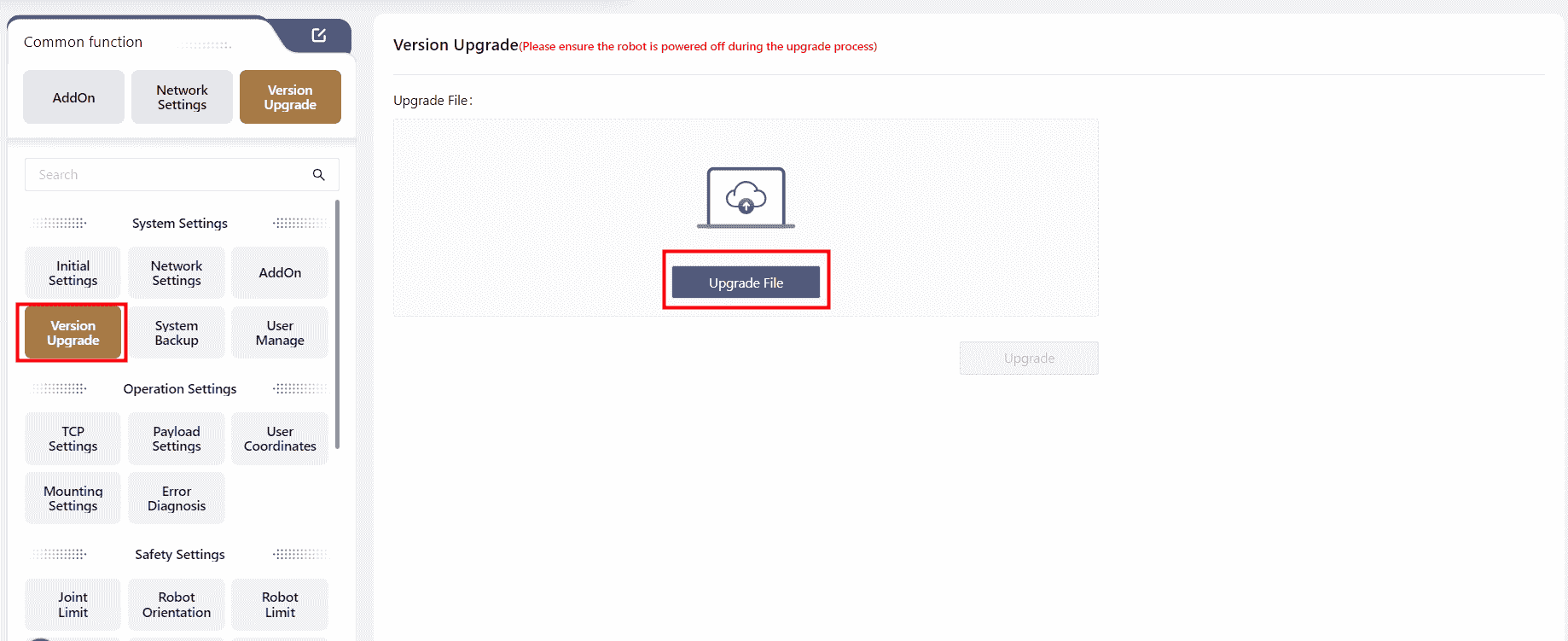
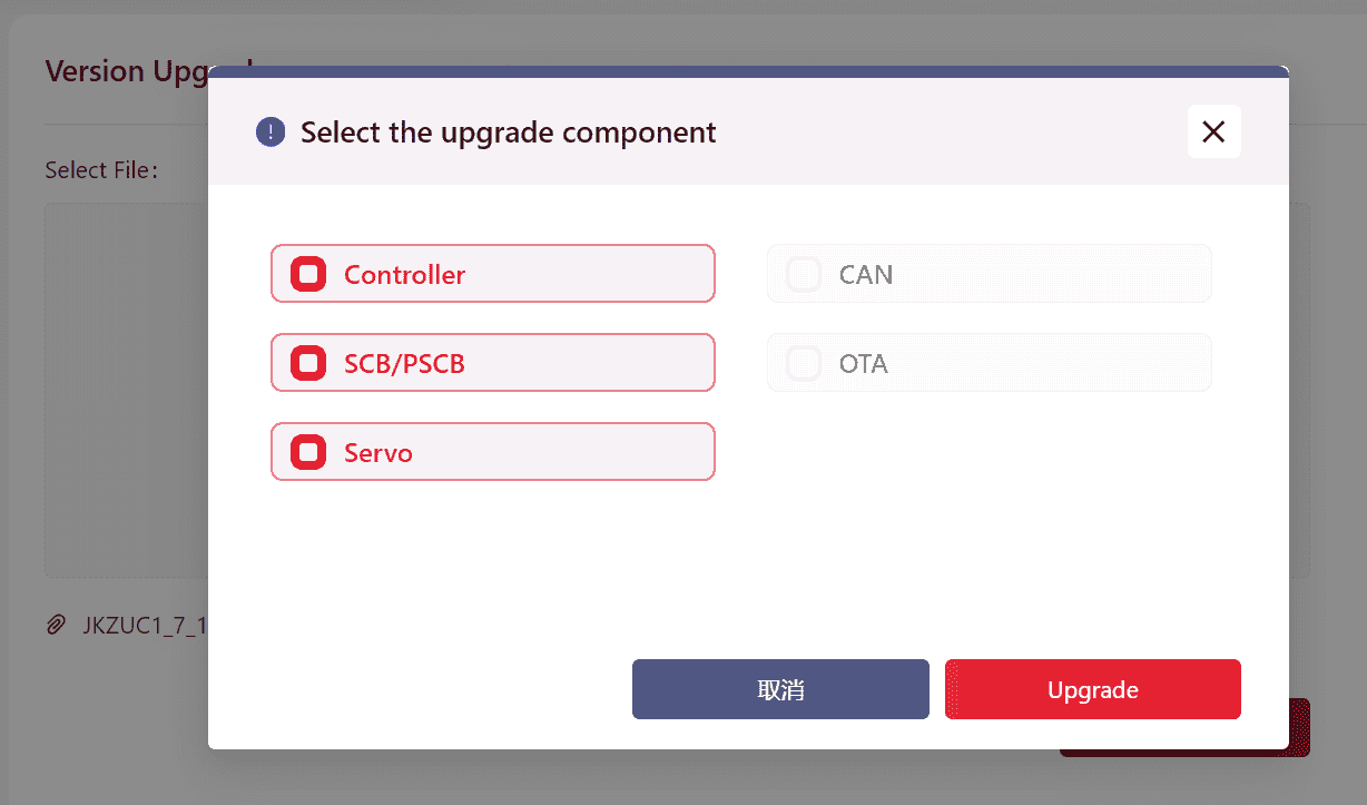
Users can upgrade the robot's controller, SCB, and servo versions in this interface.
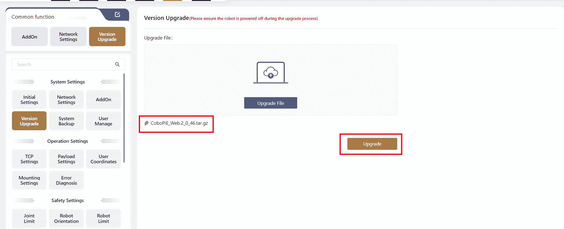
After clicking Select File , the selected file will appear on the interface. At this point, Upgrade will turn red. Click it to apply the upgrade.
Note:
The correct upgrade sequence is: Upgrade Controller → Upgrade App → Upgrade SCB → Upgrade Servo.
If only one component needs upgrading, proceed directly with that upgrade.
If multiple components need upgrading, follow the sequence above.
- If only upgrade a single component, follow the steps of General Upgrade:
- Download the upgrade package to the local device.
- Open Coboπ and connect to the robot, ensuring that the robot is powered-off and disabled.
- Click
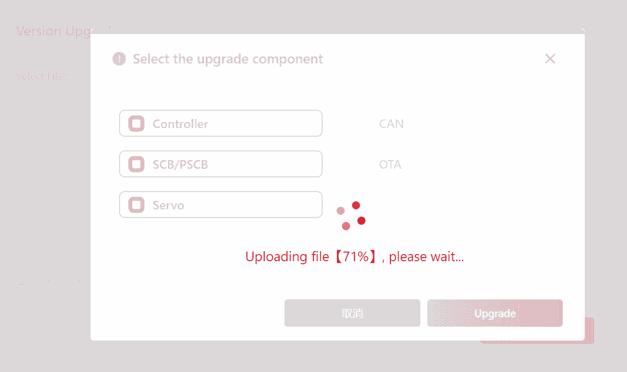
Select Fileto locate and upload the upgrade package. The file should have a .tar.gz extension (do not change the file name; it must remain as originally provided). - During the upgrade of the controller and servo, the controller will automatically restart. The upgrade is complete when the restart is finished, and the handle light turns blue.
- When upgrading the SCB, a progress window will appear. After the upgrade is complete, the controller will shut down. To restart the control cabinet, press and hold the handle switch button for 3-5 seconds.
- If the upgrade package includes the controller, SCB, and servo, follow the One-Click Upgrade Process:
- Download the upgrade package to the local device;
- Open Coboπ and connect to the robot, ensuring that the robot is in a powered-off and disabled state;
- Click
Select Fileto locate and upload the one-click upgrade package. The file should have a .jk extension (do not change the file name; it must remain as originally provided).
→ Confirm the upgrade content again, and after the upgrade is successful, the system will restart automatically and can log in again on the restarted interface.
Warning:
Before upgrading, check the SCB and PSCB versions. If the SCB version is below 02_50 or the PSCB version is below 02_00, do not proceed with the upgrade. Contact JAKA technical service team for assistance.
System Backup
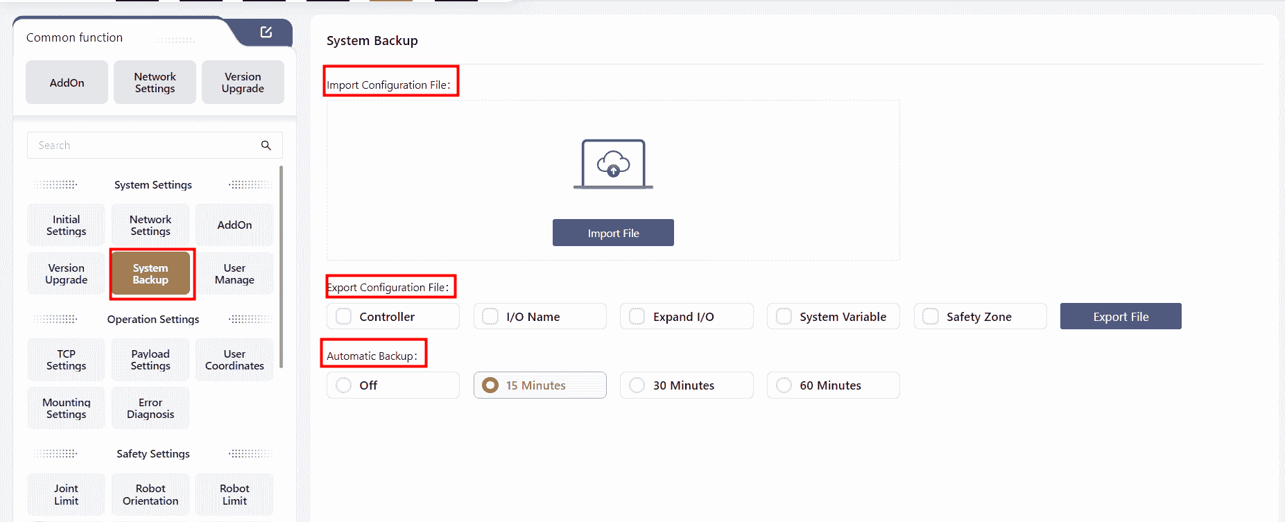
System backup includes Import/Export Configuration Files and Automatic Backup.
Import/Export Configuration Files
Configuration files store user-modified parameters during robot operation, including controller settings, I/O names, dynamic I/O, system variables, and safety zones.
- Export:Select the configuration file types to export, click "Export File", choose a save location, and click "OK" to complete the export.
- Import:Click "Import File", select the file path, and click "OK" to complete the import. After importing, manually restart the control cabinet to apply the changes.
Note:
When importing configuration files, ensure that the controller version is consistent. Importing files across different versions may cause controller errors.
Automatic Backup
When enabled, Coboπ will automatically back up the program at a specified interval after any modifications.
The backup file name will follow this format: ProgramName.SystemTime.
To view backup files, go to the Program interface and click File - Backup.
Backup files cannot be run directly. Save the backup file as a new file before running.
In version 172, after importing a configuration file, a pop-up window will ask the user whether a restart is required.
Clicking confirm will automatically restart the system.
User Management
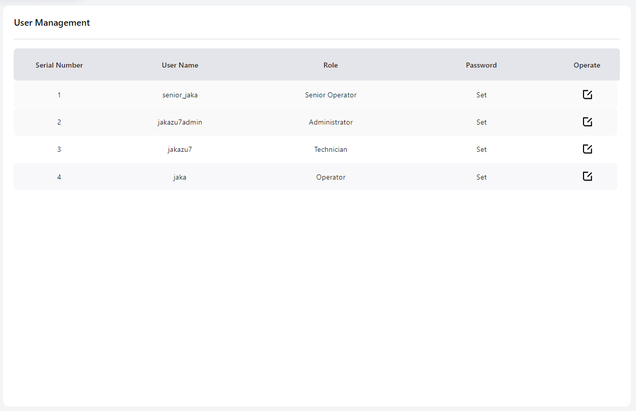
In this interface, the Administrator can modify the login passwords for different user levels.
The default passwords are as follows:
- Technician: 0000
- Operator: 0
- Administrator: jakazuadmin
- Senior Operator: s0
Senior Operator & Operator:
In programming, senior operator can modify and teach positions, and the pose, speed and acceleration in move commands.
It is recommended to change the password upon first use.
Ensure that the new password is stored securely. If the password is forgotten, contact JAKA technical support for a reset.
Restore to Factory Settings
This feature is available in version 172.
Note:
When performing this operation, ensure the robot is powered off and disabled.
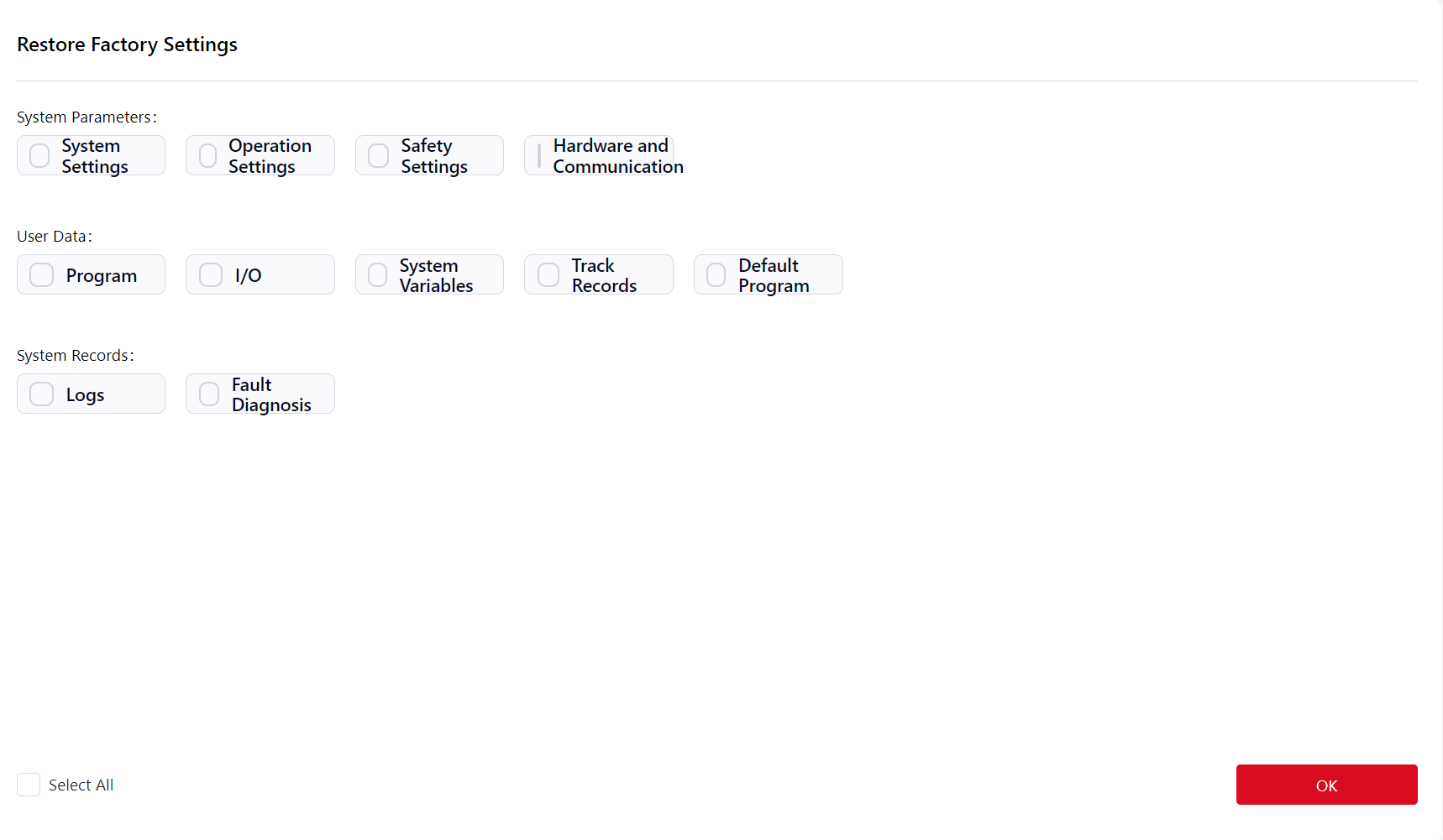
On this interface, users can choose specific options to restore to factory settings or click the Select All button in the to reset all options in the list.
After selecting the desired options, click Confirm,there will be a popup window:
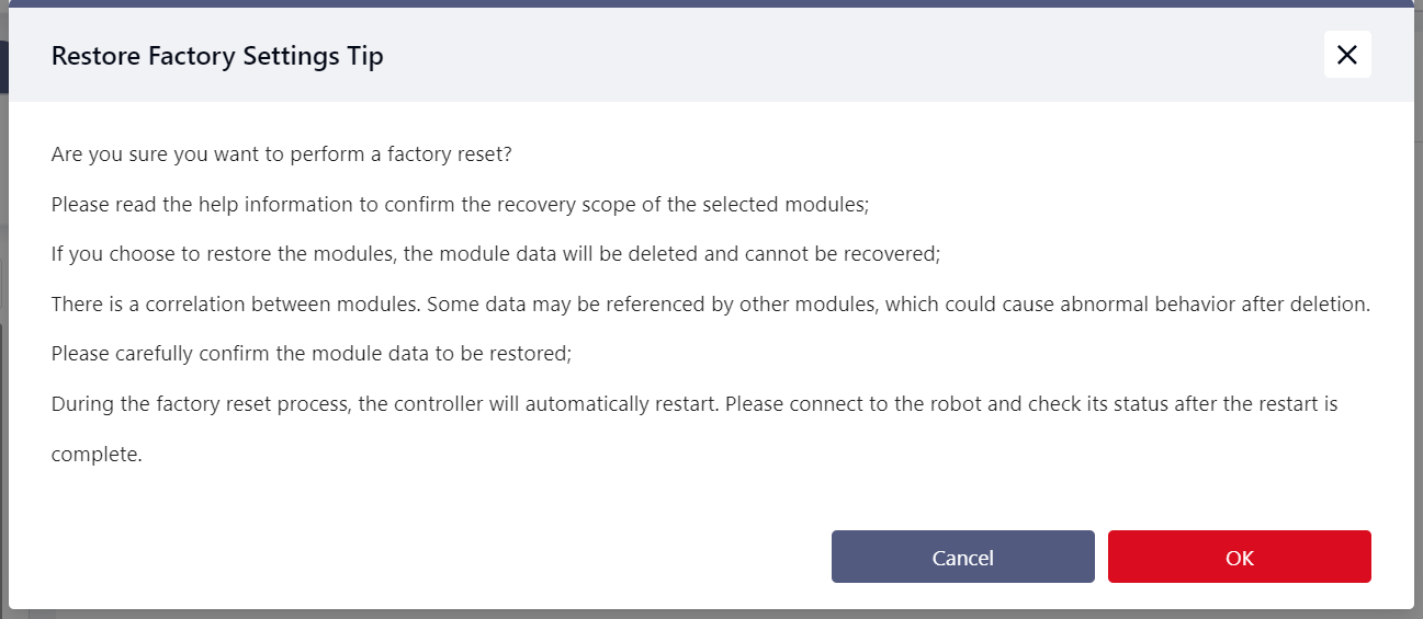
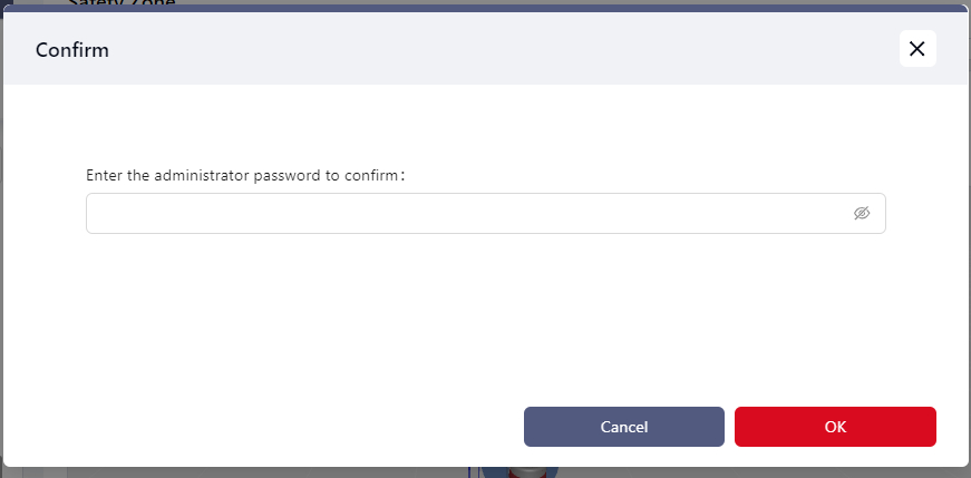
Click Confirm again, then enter the administrator password:
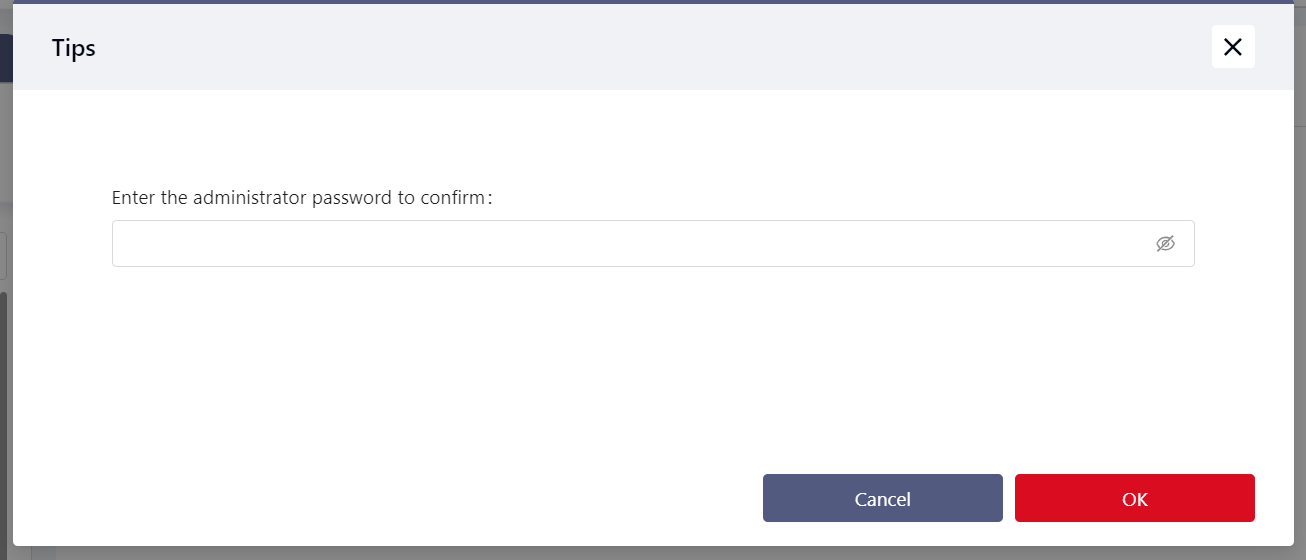
After entering the password, click Confirm. The page will display a prompt indicating that the restoration is in progress.
Afterwards, the robot restarts, and the restore is successful after the reboot.
Detailed descriptions are as follows:
System Parameters
- System Settings:
- Robot Name: Restored to "JKROBOT".
- Network Settings: Reset to obtain IP address automatically.
- Add-on Programs: Remove all add-ons except "System_Addon".
- User Management: Reset to default username and password.
- Operation Settings:
- TCP Settings: Reset TCP names and parameters to default values.
- Payload Settings: Manual input mode data reset to 0; clear auto-detection results.
- User Coordinate Settings: Reset user coordinate names and parameters to default values.
- Installation Settings: Clear set installation angles.
- Safety Settings:
- Joint Limits: Restore default joint limits for the current robot model.
- Robot Postures: Reset all configured robot postures, including factory posture, open posture, initial posture, initial posture error, and motion speed.
- Robot Restrictions: Reset all robot-related restrictions to default values.
- Safety Zones: Clear all safety zone settings.
- Tool Postures: Clear all tool posture settings.
- Dedicated Safety I/O: Clear all safety I/O settings.
- Hardware and Communication:
- Modbus Parameter Settings: Reset Modbus TCP/IP to port 6502.
- End Sensor: Reset all settings related to the end sensor to default values.
- PROFINET Settings: Disable PROFINET and clear device parameters.
- EtherNet/IP Settings: Disable EtherNet/IP and clear device parameters.
- Auxiliary Hardware Settings: Reset all related settings to default values.
User Data
- Programs:
- Delete all programs.
- Delete all program waypoint data.
- I/O:
- Clear all configured functional I/Os.
- Clear all functional I/O names.
- Clear parameters related to functional I/Os.
- Clear speed multiplier configurations.
- Clear extended I/O configurations.
- Delete all added extended I/Os.
- Reset auto-reconnect configurations to default values.
- System Variables: Delete all system variables.
- Trajectory Records: Delete all trajectory record files.
- Default Programs: Restore all configurations on the "Default Programs" interface.
System Records
- Logs: Clear all content in the "Logs" interface.
- Fault Diagnosis: Delete all diagnostic folders and files.
Operation Settings
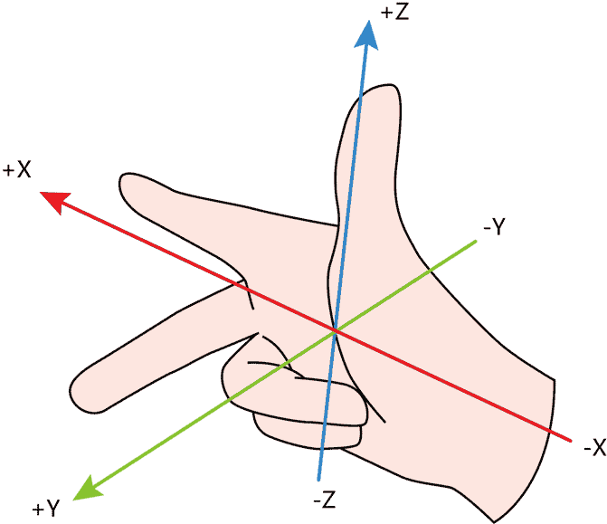
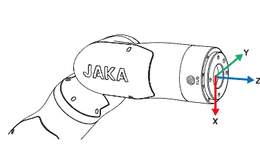
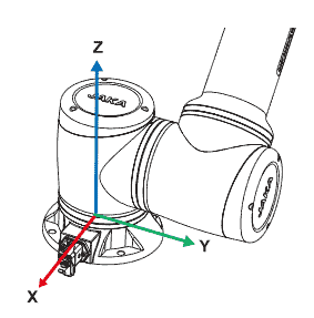
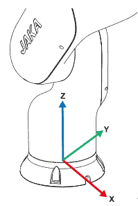
When using the robot, multiple coordinate systems can be selected, including the World Coordinate System, Flange Coordinate System, Tool Coordinate System, and User Coordinate System.
The World Coordinate System and Flange Coordinate System are the default coordinate systems, while the Tool Coordinate System and User Coordinate System are user-defined.
All of these coordinate systems follow the right-hand rule, as shown in the diagram below:
TCP Settings
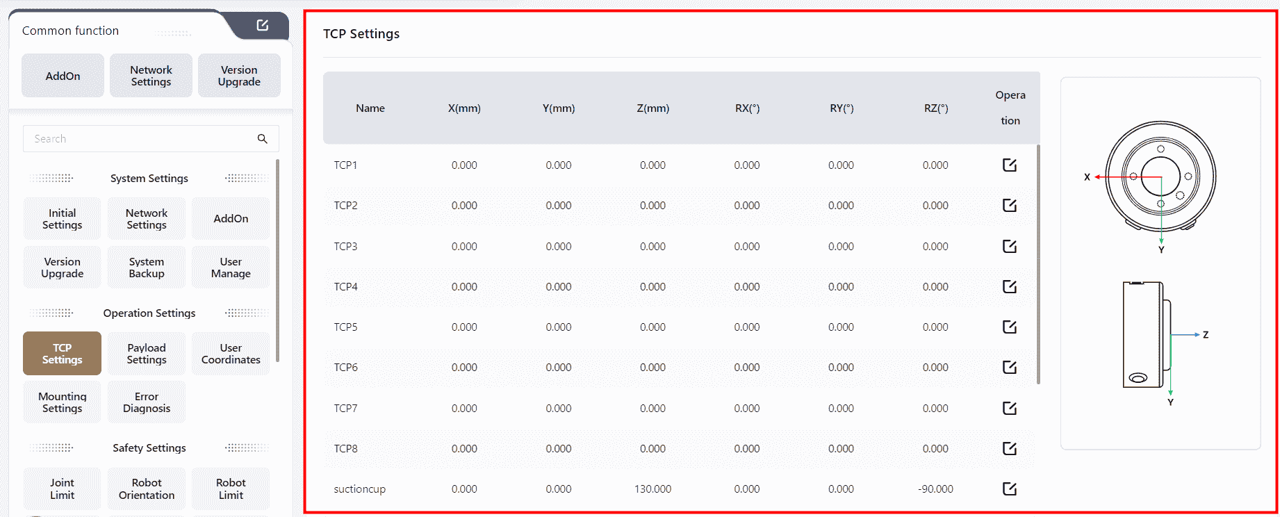
The Tool Coordinate System is established with the Tool Center Point (TCP) as the origin. It represents the position of the robot's tool, requiring manual calibration. In the context of JAKA Coboπ, TCP refers to the Tool Coordinate System. When the robot's tool is replaced, the Tool Coordinate System needs to be recalibrated.
The robot's end position refers to the Cartesian coordinates of the robot's end center point in the current user coordinate system. The robot's end orientation represents the orientation of the Tool Coordinate System in the current user coordinate system, expressed using the Roll-Pitch-Yaw (RPY) method, displayed as RX RY RZ on the interface.
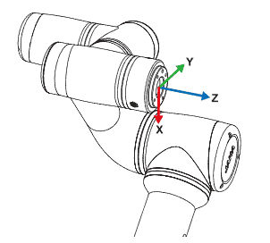
The Flange Coordinate System is the robot's default tool coordinate system. It uses the robot's flange center as the coordinate system origin, with the flange face pointing in the positive Z-axis direction. The connection between the flange center and the TIO points in the negative Y-axis direction, and the positive X-axis direction is determined by the right-hand rule.
The diagrams below illustrate this:
Since the flange coordinate system parameters cannot be modified, the TCP is usually set at the end of the robot's end-effector (e.g., the center of the gripper or suction cup) in applications where high precision is required.
JAKA Coboπ supports the configuration of 15 editable TCP parameters.
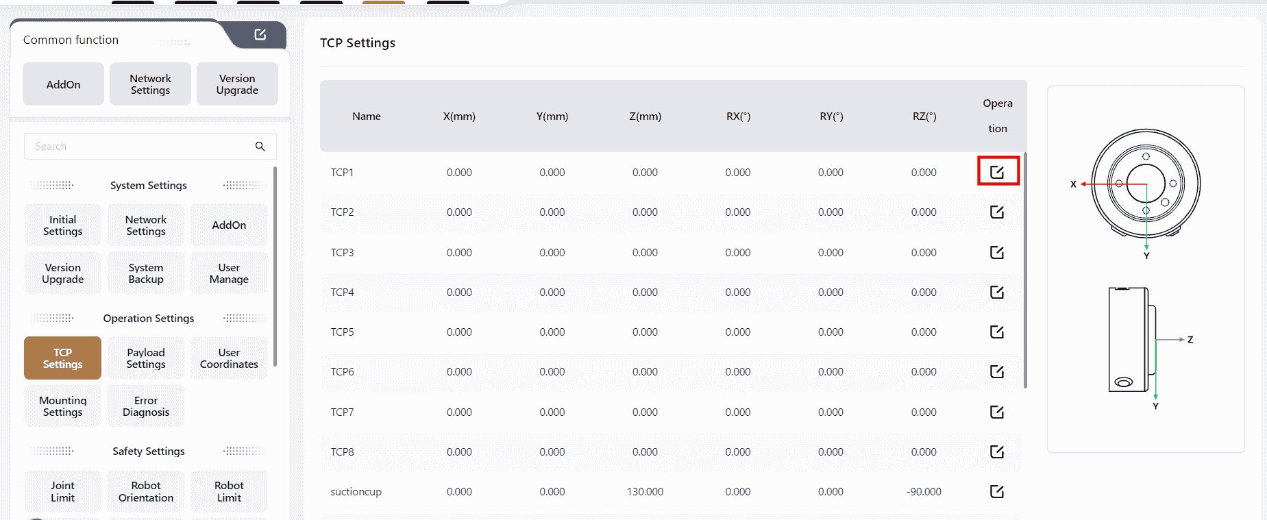
Users can choose from three different methods to set the TCP based on their needs.
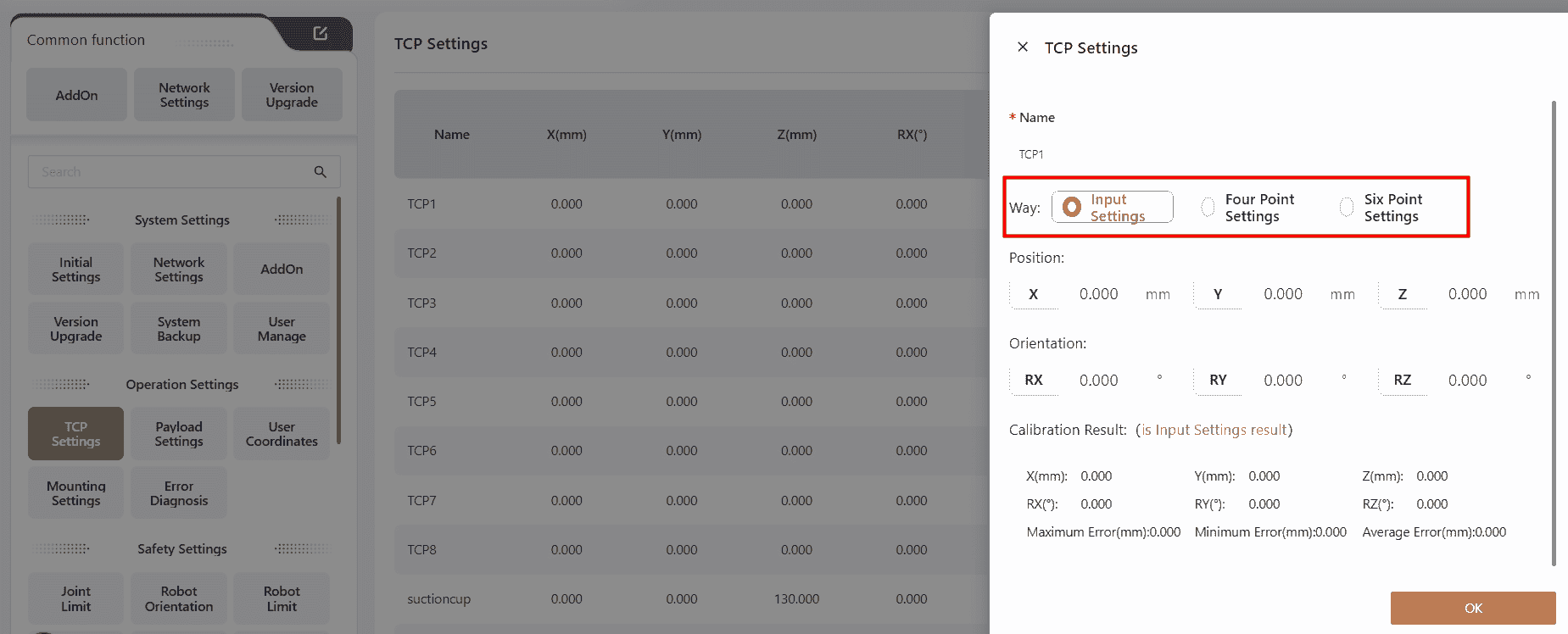
Input Settings
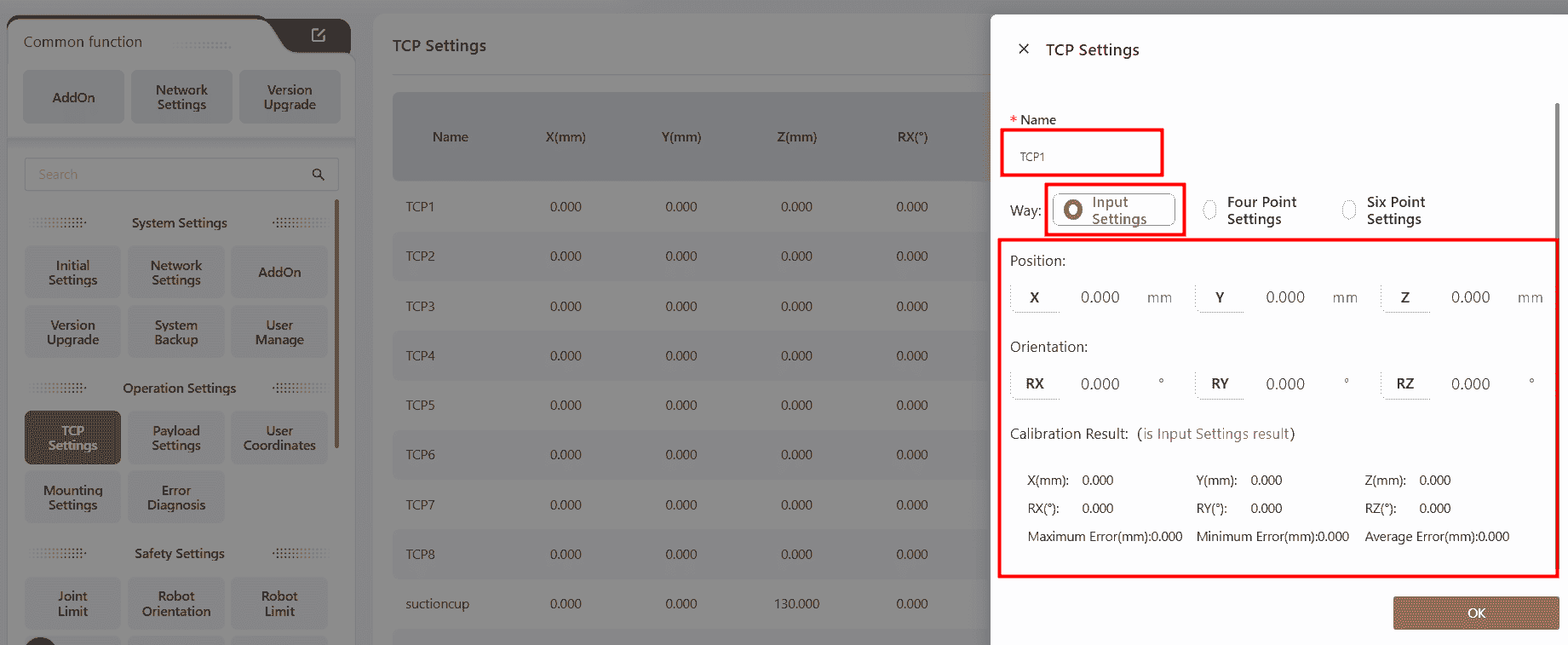
Directly input data into the corresponding fields to configure settings. After calibration, the results and errors will be displayed.
Four-Point Calibration
Identify a fixed point in space, and control the robot to bring the TCP to this fixed point using four different orientation. This method allows the system to calculate the desired pose offset of the tool coordinate system relative to the flange coordinate system.
Click on any position within the Position Point box, and the page will automatically redirect to the manual operation page. The user can control the robot's movement on this page to set the four position points or directly use the robot's teaching method to set the points.
The steps are as follows:
- Find a fixed reference point within the robot's reachable range, such as the tip of a cone.
- Click
Point_1,operate the robot to bring the end of the actuator to the reference point, and click Confirm. - Click
Point_2,operate the robot to bring the actuator's end to the reference point at a different joint angle from Position Point_1, and click Confirm. - Click
Point_3,operate the robot to bring the actuator's end to the reference point at a different joint angle from Position Points_1 and 2, and click Confirm. - Click
Point_4,operate the robot to bring the actuator's end to the reference point at a different joint angle from Position Points_1, 2, and 3, and click Confirm. - Click
Calibrate,to obtain the parameters of the desired tool coordinate system. - After calibration, the results and errors will be displayed.
Six-Point Calibration
Building upon the Four-Point Calibration, an additional two position points are specified to determine the TCP coordinate axis direction, automatically calculating the TCP's position and orientation parameters. This method is used to calculate the parameters of the desired tool coordinate system.
Six-Point Calibration is commonly used when the tool's axis at the robot's end is not perpendicular or parallel to the robot's flange. This method ensures that the tool coordinate system's Z-axis aligns with the robot's end axis.
The steps are as follows:
- Find a fixed reference point within the robot's reachable range, such as the tip of a cone.
- Click
Point_1,operate the robot to bring the end of the actuator to the reference point, and click Confirm. - Click
Point_2,operate the robot to bring the actuator's end to the reference point at a different angle from Position Point_1, and click Confirm. - Click
Point_3,operate the robot to bring the actuator's end to the reference point at a different angle from Position Points_1 and 2, and click Confirm. - Click
Point_4,operate the robot to bring the actuator's end to the reference point at a different angle from Position Points_1, 2, and 3, and click Confirm. Position Point_4 will serve as the origin of the desired tool - Click
Point_5,operate the robot, keeping the pose of Position Point_4 unchanged, and move from Position Point_4 along the positive direction of the desired tool coordinate system's Z-axis to a new position to set Position Point_5, and click Confirm. - Click
Point_6,operate the robot, keeping the pose of Position Point_5 unchanged, and move from Position Point_5 within the desired XOY plane to set Position Point_6, and click Confirm. - Click
Confirm,to obtain the parameters of the desired tool coordinate system. The line connecting Position Points_4 and 5 will determine the positive direction of the tool coordinate system's Z-axis. - After calibration, the results and errors will be displayed.
Payload Settings
The payload refers to the mass and center of mass of all objects mounted on the robot's end.
Properly setting the payload allows the controller to accurately calculate the robot's actual operating conditions.
When the payload is correctly set, the robot's end flange will remain stable without drifting when in drag mode after pressing the robot's end button.
As shown in the image, the user should input the precise load information, including mass and center of gravity, into the corresponding fields and click Confirm to complete the settings.
Note:
Please ensure the load is correctly set. If the actual payload differs from the set payload, it may result in false collision detection, robot stopping its move, or even damage to the robot.
Note:
The center of mass is relative to the robot's end flange center. The X, Y, and Z coordinates of the center of mass are spatial values in the flange coordinate system. It is recommended to use 3D design software for calculation to improve accuracy.
If the Load Deviation Detection is enabled:
Tips
Warning Threshold: The maximum value that can be set here is the rated maximum load of the robot model. Once configured, the system will perform a load deviation check on the robot every time it is enabled. If the deviation of the actual load is ≥ the set warning threshold, an alert notification will appear at the top of the interface.
Drag Limit Threshold:The maximum value configurable here is limited by the robot model's rated maximum load. Once set, the system will perform a load deviation check every time freedrive mode is initiated. If the deviation ≥ the configured drag restriction threshold, entering freedrive mode will be prevented.
Auto identification mode
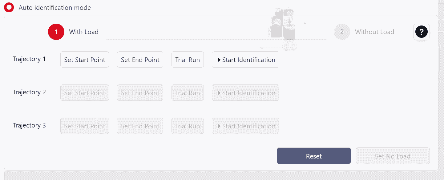
Auto identification mode utilizes the robot’s motion across axes 3, 4, 5, and 6, i n both loaded and unloaded states, to calculate the end-effector's mass and center of gravity. The process includes the following steps:
Initially, the robot must execute the same trajectory in both loaded and unloaded states. Begin with the
With Load.Attach the load and move the robot to position (0°, 90°, 0°, 0°, 180°, 0°) with a vertical orientation. This position serves as the baseline pose for the recognition process.
Set Up
Trajectory 1:- Click
Set Start Point,Enter the manual control interface and configure the starting point.- For Trajectory 1, ensuring it meets these constraints: Joint 2 is 90°, Joint 3 is 0°, Joint 4 is within (-60°, 60°), Joint 5 is 180°, and Joint 6 matches Joint 4's angle. If any condition is unmet, a Coboπ pop-up will prompt correction.
- Once set, click
Confirm.
- Click
Set End Pointto enter manual control and set the point position.- The end point must match the start point conditions, with an additional requirement that Joint 4’s angle differs by at least 10° between start and end.
- Once set, click
Confirm.
- Click
Test
Trajectory 1:- Long press
Set Start Pointto return to the initial point. - Long press
Trial Runto move the robot from the start point to the end point, ensuring no interference along the trajectory.
- Long press
Identify
Trajectory 1:- Click
Start Identification - Upon trajectory completion, this button will show the Identification is complete.
- Click
Set Up
Trajectory 2:- Click
Set Start Pointto enter manual control and set the point position.- The initial point for Trajectory 2 must meet these requirements: Joint 2 at 90°; Joint 3 at 0°; Joint 4 between -60° and 60°; Joint 5 at 180°; Joint 6 at 90° greater than Joint 4’s angle. If any requirement is not met, Coboπ will display a prompt.
- Once set, click
Confirm
- Click
Set End Pointto enter manual control mode and set the point position- The end point must match the start point conditions, with an additional requirement that Joint 4’s angle differs by at least 10° between start and end.
- After setting, click
Confirm.
- Click
Test
Trajectory 2:- Long press
Set Start Pointto return to the initial point.. - Long press
Trial Runto move the robot from the start point to the end point, ensuring no interference along the trajectory.
- Long press
Identify
Trajectory 2:- Click
Start Identification - Upon trajectory completion, this button will show the Identification is complete.
- Click
Set Up
Trajectory 3:- Click
Set Start Pointto enter manual control and set the point position.- The initial point for Trajectory 3 must meet these requirements: Joint 2 at 90°; Joint 3 at 0°; Joint 4 at 0°; Joint 5 between 170° and 180°. If any requirement is not met, Coboπ will display a prompt.
- Once set, click
Confirm.
- Click
Set End Pointto enter manual control mode and set the point position.- The end point must meet these requirements: Joint 2 at 90°; Joint 3 at 0°; Joint 4 at 0°; Joint 5 between 180° and 190°, ideally totaling 360° with the initial Joint 5 angle; Joint 6 aligned with its initial angle. If any requirement is not met, Coboπ will display a prompt.
- After setting, click
Confirm.
- Click
Test
Trajectory 3:- Long press
Set Start Pointto return to the initial point. - Long press
Trial Runto move the robot from the start point to the end point, ensuring no interference along the trajectory.
- Long press
Identify
Trajectory 3:- Click
Start Identification - Upon trajectory completion, this button will show the Identification is complete.
- Click
After confirming completion of recognition for all three trajectories, remove the load, and click
Witout Loadto switch to Without mode. No need to reset the trajectories; proceed with recognition for each trajectory in unloaded mode.When both loaded and unloaded recognition are complete. A pop-up window will display the recognition results.
User coordinates
The user coordinate system is established on the workpiece and can be set by directly inputting values or by teaching points, where the robot calculates the coordinate system based on the taught points.
If the workpiece position changes, the user coordinate system needs to be recalibrated.
The world coordinate system is the default user coordinate system and its parameters cannot be modified. It has its origin at the robot's base center. When the robot is in its standard orientation, the base's vertical direction towards the robot body is the positive Z-axis direction, the line connecting the base center with the load line interface is the positive X-axis direction, and the positive Y-axis direction is determined by the right-hand rule, as shown in the diagrams.
JAKA Coboπ supports the configuration of up to 15 editable user coordinate systems.
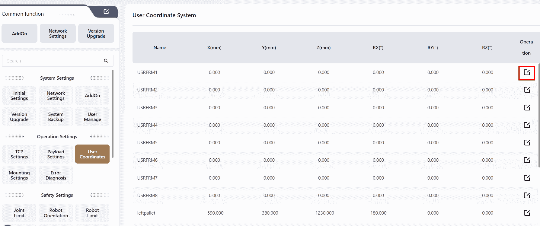
Users can choose either of the following two methods based on their needs:
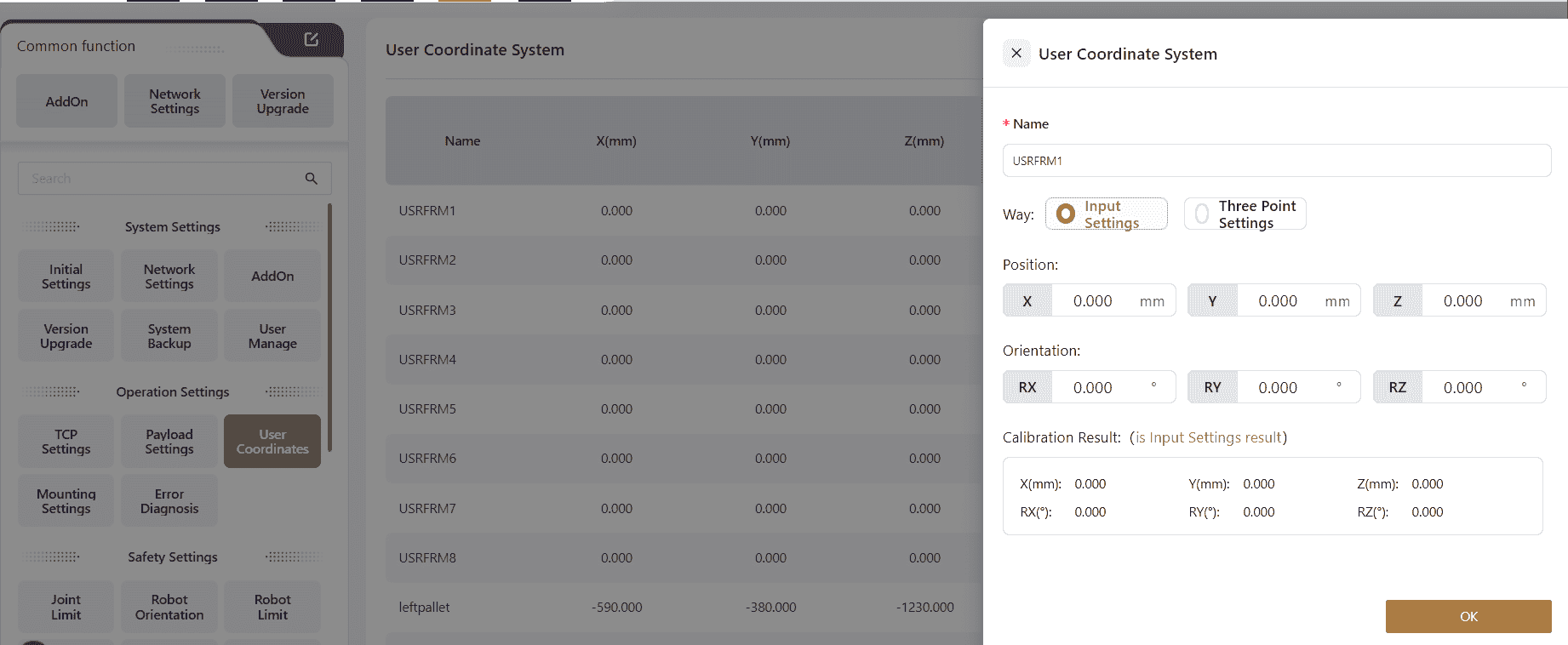
Input Settings
The user inputs the data into the corresponding fields, clicks Confirm, and completes the user coordinate system parameter editing. The calibration results will then be displayed.
Three-Point Calibration
The user teaches three position points, and the robot automatically calculates the parameters for the desired user coordinate system in the X, Y, and Z directions.
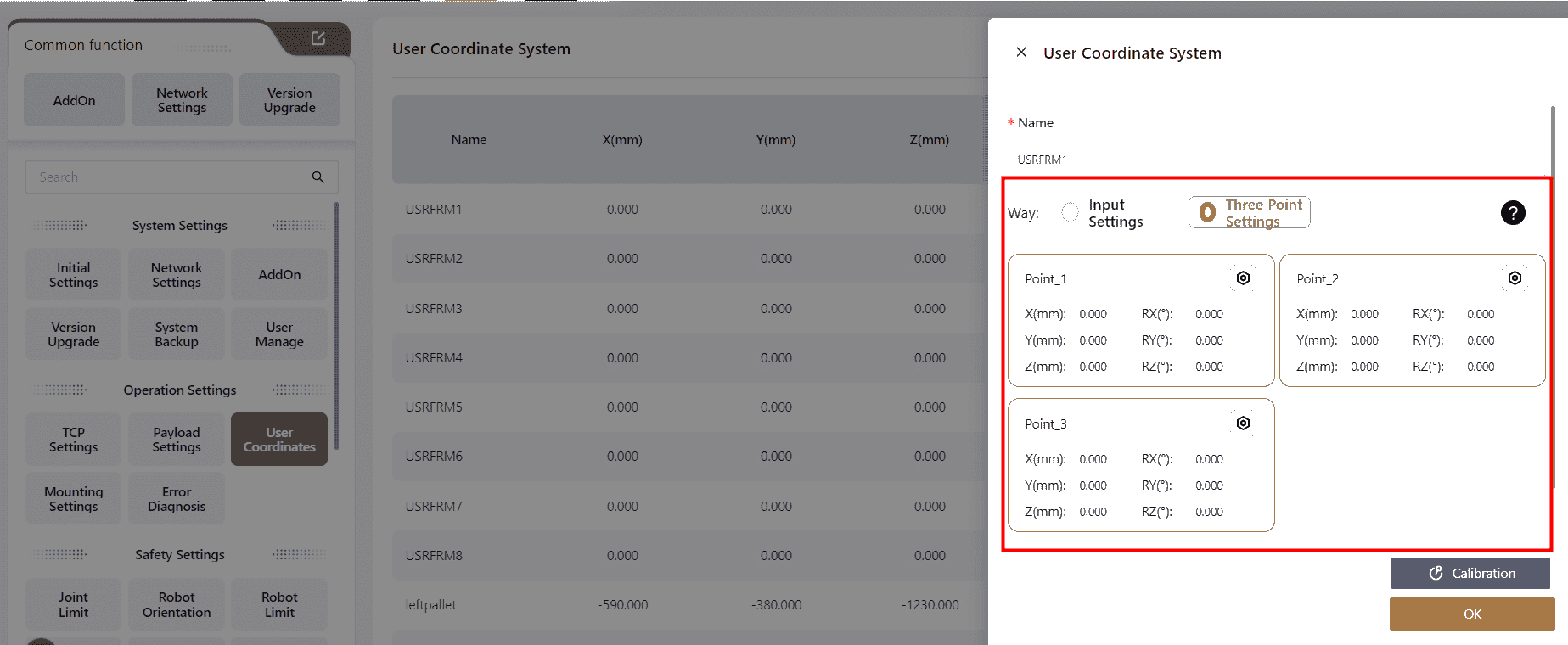
Click on any position within the Position Point box, and the page will automatically redirect to the manual operation page. The user can control the robot's movement on this page to set the three position points or directly use the robot's teaching method to set the points.
Point_1 This sets the origin of the user coordinate system.
Point_2 This sets any point in the positive X-axis direction of the user coordinate system.
Point_3 This sets any point in the first quadrant of the user coordinate system's XOY plane.
The coordinate system chosen during the three-point setup should remain consistent.
Once the points are set, the calibration results will be displayed.
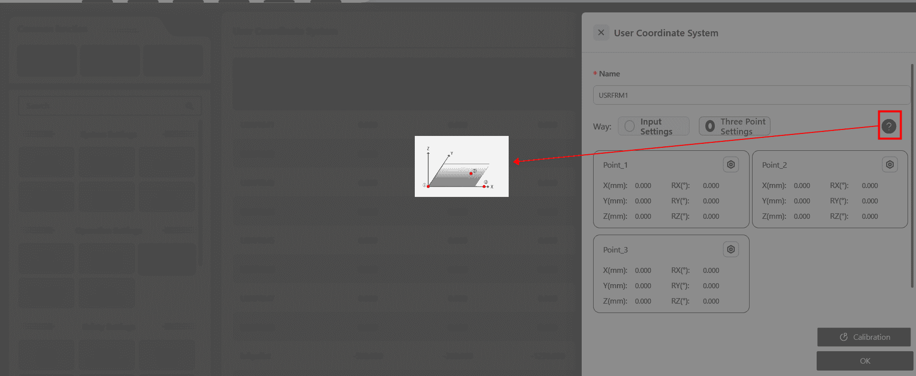
Click ?,to reference the instructional diagram:
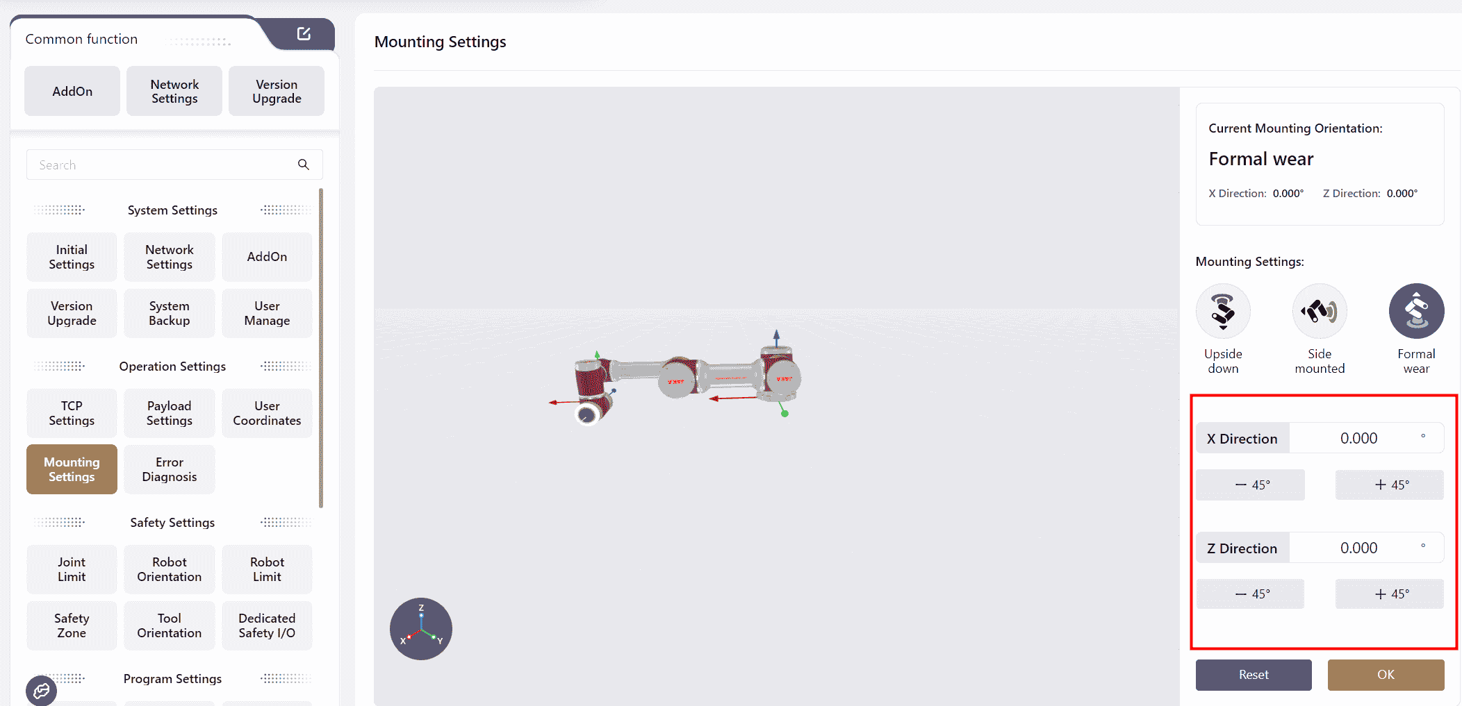
Mounting Settings
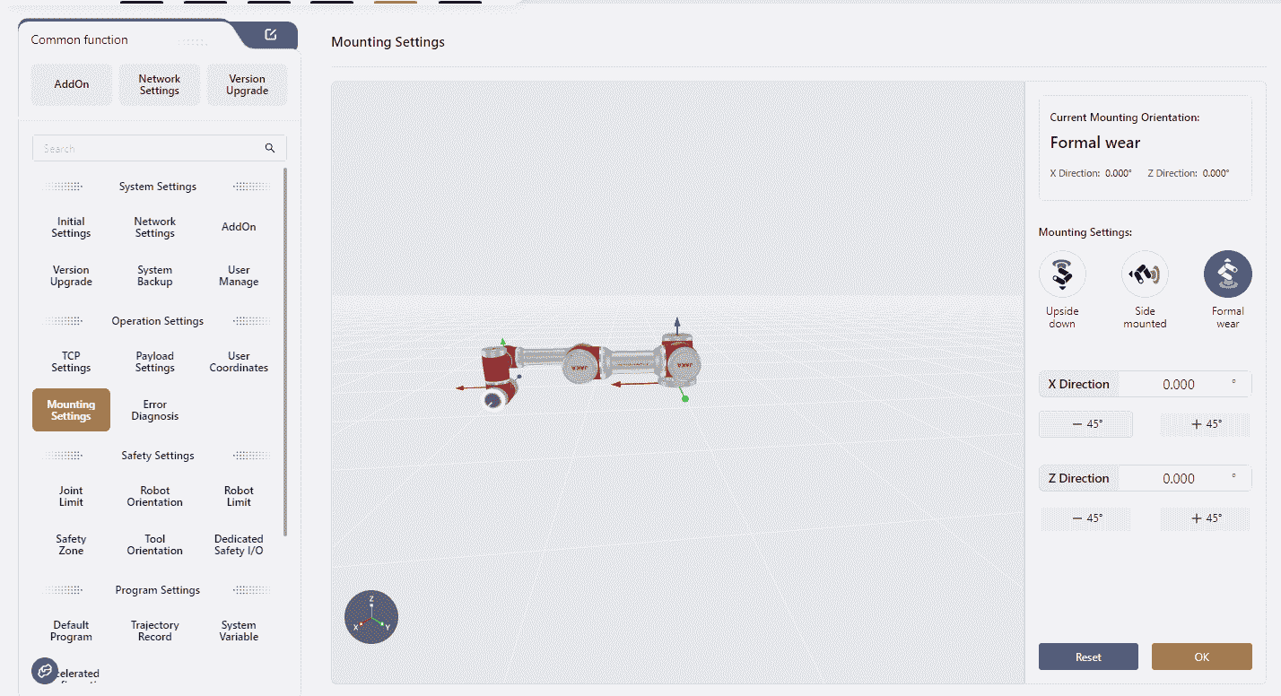
JAKA robots can be mounted at any angle.
After mounting, it is necessary to record the robot's actual mounting orientation in this interface to ensure operation safety. The specific steps are as follows:
In the Mounting Settings section, select the robot's actual mounting orientation.
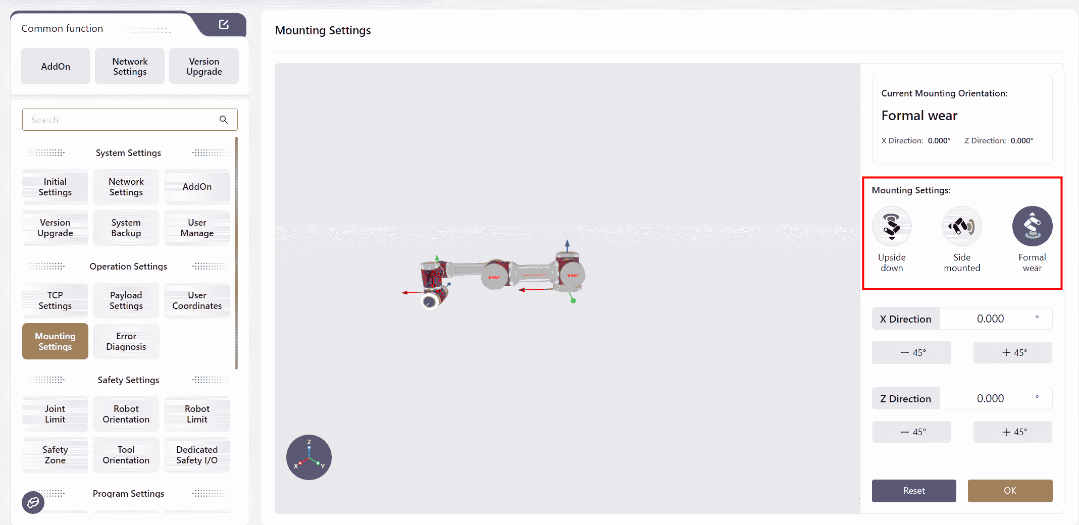
After selecting, adjust the robot model in the X Direction and Z Direction fields to align it with the robot's actual orientation.
Error Diagnosis
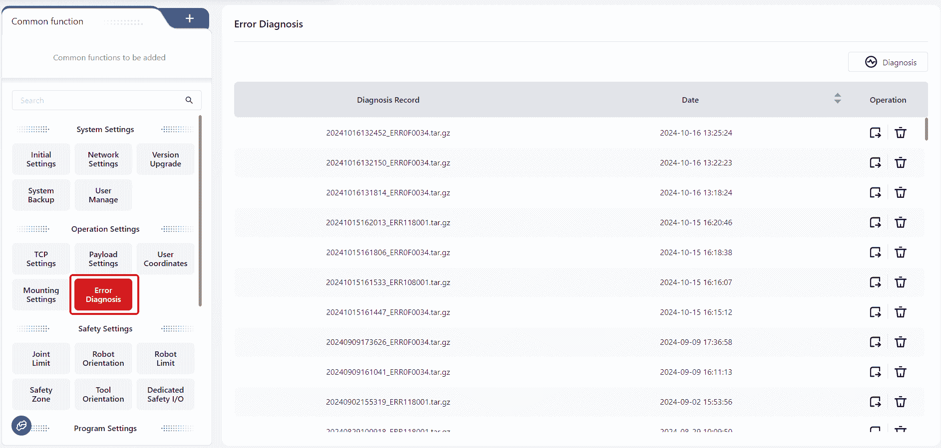
When an error occurs, the controller automatically saves error information as a compressed file, named with the system time at the moment when this error happens. These compressed files are displayed in the error diagnosis interface.
The user can also manually click Diagnosis to export the error file and analyze the robot's motion status.
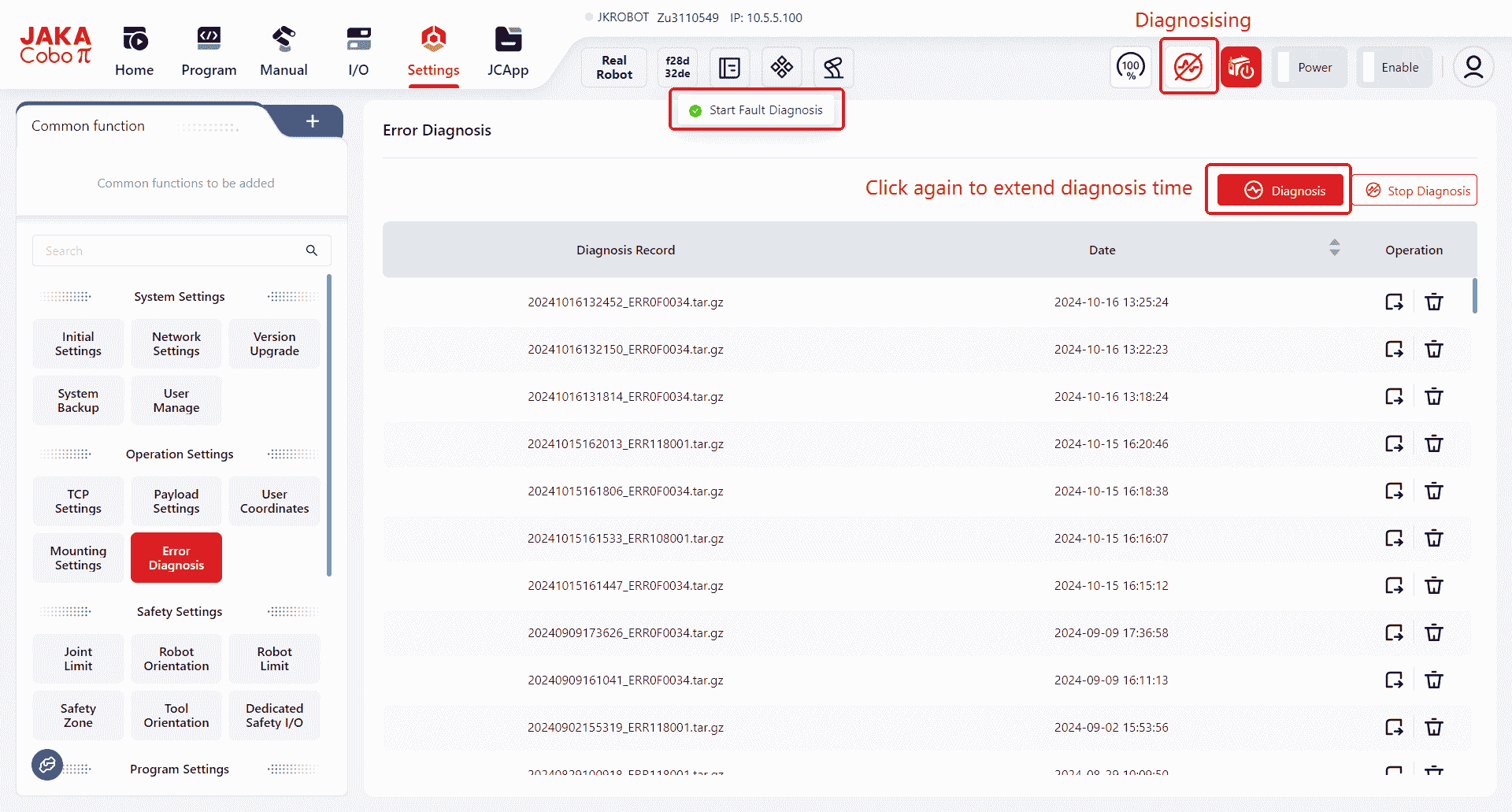
While in diagnostic mode, clicking Diagnosis extends the diagnostic duration.
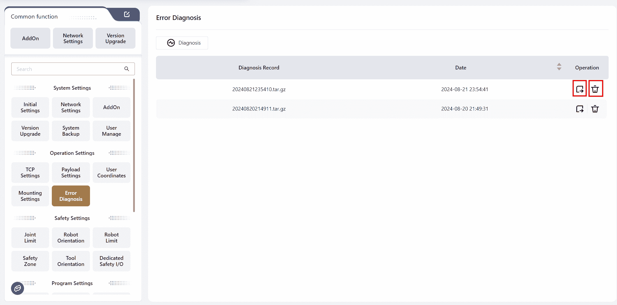
The corresponding buttons can be used to operate on the error files.
Safety Settings
Please notice:
To guarantee safe operations, entering of administrative password is required when change important safety parameters.
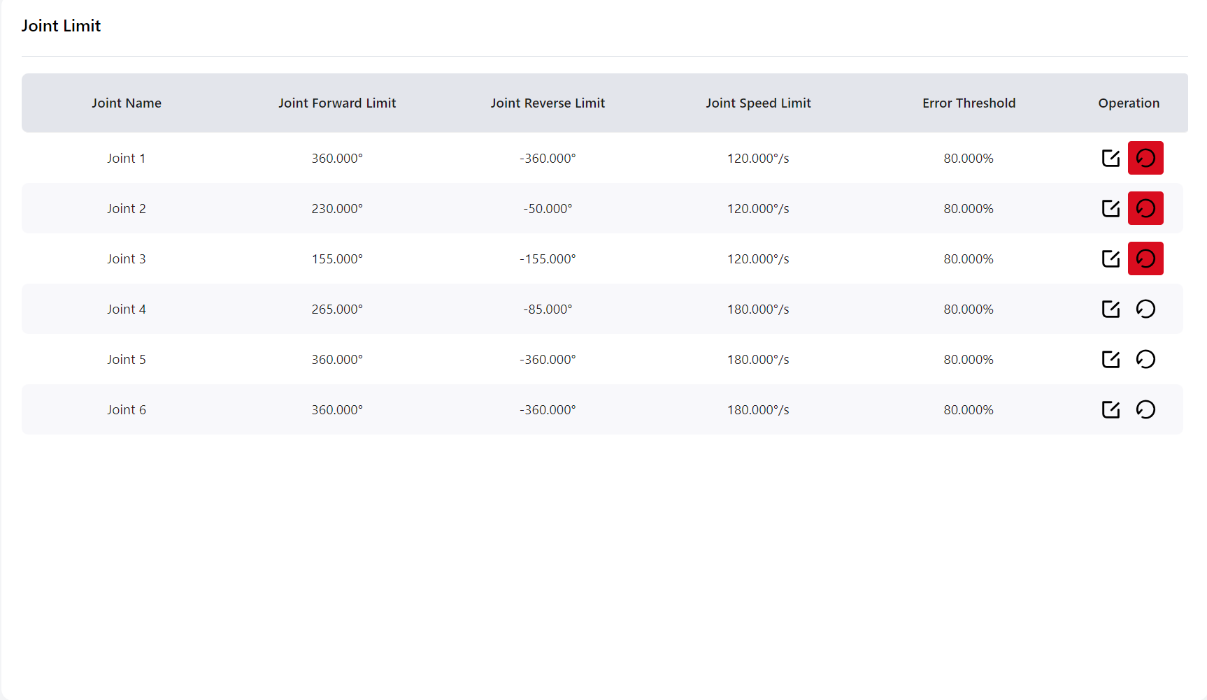
Joint Limits
In this interface, users can set the soft limit angles, speed limits, and error alarm thresholds for each joint.
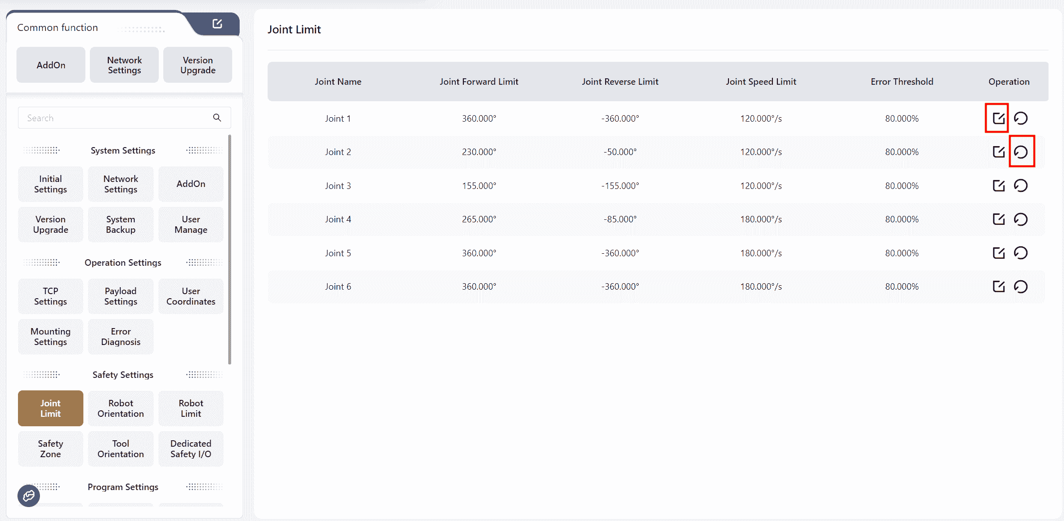
Can click the button to perform the corresponding operation.
Note:
- The ranges for
Joint Forward LimitJoint Reverse LimitJoint Speed Limitare based on the default values shown on the interface. Users can only adjust the values within these ranges. Error Thresholdrefers to the threshold at which the robot will trigger an alarm when the motion deviation exceeds the set threshold (default is 80%).Resetrestores the default values.
In version 172, if the joint limit here is not the default value,the reset button on the right will appear in red:
Robot Pose
In this interface, users can set the robot's Factory Pose Open Pose Safe Pose,clicking the icons on the right will redirect to an operation page for setting these orientation. Users can also move the robot into any other orientation, then enter this page and click Move to Target under Factory Pose Open Pose Safe Pose to move the robot to the corresponding pose.
Factory Pose: The pose in which the robot is packaged.
Open Pose: The zero pose is used for joint mechanical zero-point calibration.
Safe Pose: A user-editable pose that can be set as the initial pose. Pressing the Home button on the controller will move the robot to this pose. When the robot reaches the initial pose, the "Initial Pose" function I/O can be triggered.
Safe Pose Error: Users can set the range between 0.001 and 3. When the difference between the current joint angles and the corresponding joint angles of the safety posture is within this tolerance, the DO linked to the safety position function will be triggered.
Speed:This controls the speed at which the robot moves to the target point.
Motion Limits
Collision Settings
Quick Setting
Here, users can set the robot's collision protection sensitivity. Higher sensitivity means the robot is less likely to report a collision during motion.
Custom
Users can adjust specific options to configure collision protection sensitivity.
Force Limit The force required to trigger a collision alarm when the robot contacts an external environment. A higher percentage means more force is required to stop the robot.
Momentum Limit TCP Velocity Limit Power Limit Stop Time Stop Distance affect the robot's speed. Lower values result in slower robot operation.
Collision Response Settings
In this interface, users can set the rebound angle after a collision, ranging from 0° to 3°. If set to 0°, the robot will not rebound after a collision.
If a minor collision is detected during program execution (when the joint angle feedback position deviates by approximately 1° from the commanded position), the robot will stop and terminate the program. In the event of a severe collision (when the joint angle feedback position deviates by approximately 3.6° or more), the robot will stop and disable itself.
In manual mode, if a collision occurs, the robot will not rebound regardless of the rebound angle setting. Moreover, if an external force is continuously applied, the robot can be pushed within a certain range.
Reduced Mode Settings
In this interface, users can set various limit values for the robot in reduced mode.
Values can be set by dragging the sliders or by entering numbers directly. The default maximum range for these settings is based on the maximum values for the currently connected model.
After clicking Confirm to apply the settings, the interface will prompt that "Safety verification parameters have changed".
Drag Speed Limitation
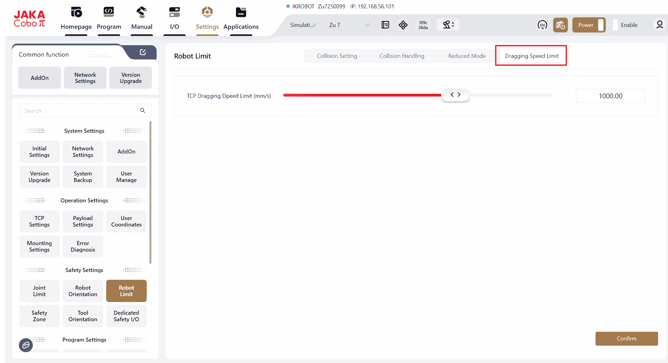
In this interface, users can set the TCP (Tool Center Point) drag speed of the robot, with a range of 50 to 1500 mm/s.
This speed setting only affects the TCP speed when dragging the robot. If the drag speed exceeds the set limit, the robot will stop moving, remain enabled, and exit drag mode.
Safety Zones
Users can configure safety zones in this interface to restrict the movement range of the robot's end or elbow (joint 3) to prevent collisions with other objects during operation.
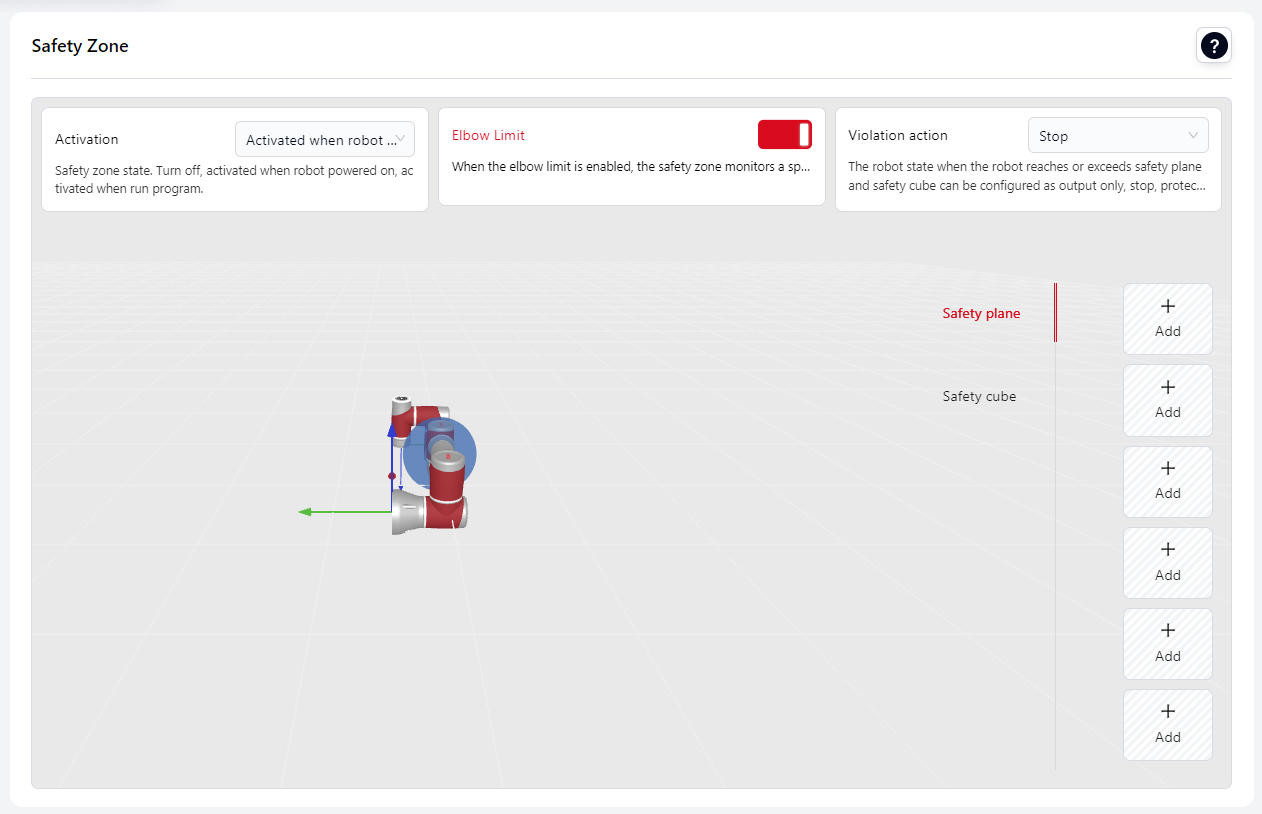
Before configuring a single safety plane or safety cuboid, the following configuration options that apply to all safety planes and cuboids must be set.
Activated when robot powered on: means that the safety zone is active immediately after the robot is powered on.
Activated whn run program: means that the safety zone is only active during program execution. It is not active during drag, manual operation, or SDK-controlled robot movement.
Elbow Limit:
When this switch is turned on, the safety plane will also apply to the robot's elbow (joint 3 region), effective within a spherical area surrounding the elbow.
Violation Action:
Specifies the robot's response when it reaches or exceeds the safety plane.
- Stop: The robot stops, the program terminates, and the robot disables itself. It can be re-enabled within the safety zone.
- Protective Stop: The robot decelerates to a stop, the program pauses, and a popup displays "Safety Plane Protective Stop". Click "OK" to exit the protective stop and allow the robot to pass through the safety plane and continue moving. If the safety plane is triggered again, the robot will perform another protective stop. The "Protective Stop Reset Input" in the safety DI can also be triggered to exit the protective stop and continue through the safety plane.
- Reduce Mode: The robot enters reduced mode (TCP speed ≤ 250 mm/s) upon triggering the safety plane. A popup prompts "Robot Entered Reduced Mode". Click "OK", and the robot will remain in reduced mode until it returns within the safety plane.
- Output Only: When a safety plane or cuboid is triggered, the corresponding DO output signal bound to the safety plane or cuboid is activated.
Note:
Switching the robot model or coordinate system does not change the positions of the already configured safety planes.
Set Safety Plane
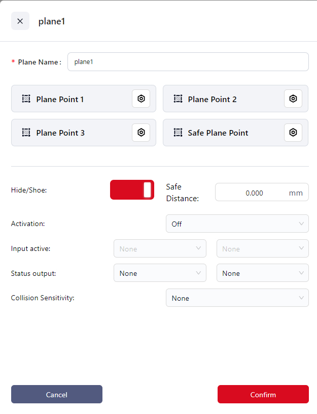
- Click
+Addto enter the setup page. - Enter the plane name in
Plane Name. - Click the icons next to
Plane Point 1, 2, 3to enter the manual operation interface and set the positions of the three plane points. The controller calculates the position of the safety plane based on these points and displays it in the 3D model area. - Click the icon next to
Safe Plane Pointto enter the manual operation interface. You can designate one side of the safety plane as the safe side and then move the robot to that side. Click "Confirm" once done. The side where the end effector's origin is located is considered the safe side. - Set the
Safe Distancewhich is the distance (in mm) between the robot's end effector and the safety plane. When the actual distance between the robot's end effector and the safety plane is less than this value, the safety plane is triggered, and the robot's motion state will change. - Choose the
Activation:
Off: Do not enable the current safety plane.
Activate: Enable the current safety plane.
Input Activate: Bind the current safety plane to a DI. When this DI receives an input signal, the safety plane is activated.
- If you choose "Input Activate", you can select the DI to bind this safety plane from the dropdown in the
Input Activationfield.
A single DI can be bound to multiple safety planes and safety cuboids simultaneously.
- If you choose "Input Activate", you can select the DI to bind this safety plane from the dropdown in the
- If you want to visually check if the safety plane is triggered, you can bind it to a DO:
From the dropdown in
Status Outputselect the DO to bind the safety plane. Once triggered, the DO's status in the I/O panel will show as "ON".A DO can only be bound to one safety plane or safety cube
- Set the
Collision SensitivityIf collision sensitivity is configured, when the robot enters a danger zone, the collision level switches to the level defined in the safety zone. When the robot returns to the safe zone, the collision level reverts to the one set in the "Motion Limit" settings. If the robot enters multiple safety zones with defined danger zones, the collision level switches to the most sensitive setting. The lower the number, the higher the sensitivity (LV1 > LV2). - Click
Confirmto save this safety plane.
Set Safety Cube
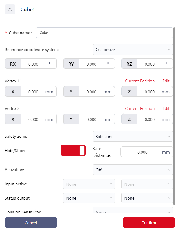
- Click
+Addto enter the setup page. - Enter a name for the cube in the
Cube Namefield. - Set the
Reference Coordinate System:- Can be set to the world coordinate system, a configured user coordinate system, or custom.
- If
Customizeis chosen, you must enter the rotation angles of the custom coordinate system relative to the world coordinate system in the RX, RY, and RZ fields. If the position of the selected user coordinate system is modified in the "User Coordinate System" interface, the reference coordinate system will automatically change to custom, with the RX, RY, and RZ values being those before the user coordinate system was modified.
- Set the
Vertex 1andVertex 2,which will be used by the controller to calculate the cube. The positions of the diagonal points are relative to the reference coordinate system. You can:- Directly enter the distances of the diagonal points from the origin of the reference coordinate system in the X, Y, and Z fields.
- Click
Editto jog or drag the robot to the target point. When dragging the robot, the diagonal point is the center of the robot’s end effector flange.
- Set the
Effective Safety Area:- Internal Safety: The inside of the cube is the safety area.
- External Safety: The outside of the cube is the safety area.
- Set the
Safe Distance:This is the distance between the robot’s end effector and the safety area, in millimeters. When the robot’s end effector is closer than this value to the safety area, the safety cube will be triggered, and the robot’s movement state will change. - Choose the
Activation:
Off: Does not enable the current safety cube.
Activate: Enable the current safety cube.
Input Activate: Bind the current safety plane to a DI. When this DI receives an input signal, the safety cube is activated.
- If you choose "Input Activate", you can select the DI to bind this safety plane from the dropdown in the
Input Activatefield.
A single DI can be bound to multiple safety planes and safety cubes.
- If you choose "Input Activate", you can select the DI to bind this safety plane from the dropdown in the
- To visually check if the current safety cube has been triggered, you can bind it to a DO:
In the
Status Outputdropdown, choose the DO you want to bind to the safety cube. When the safety cube is triggered, the status of this DO will be "ON" in the I/O panel.A DO can only be bound to one safety plane or safety cube.
- Set the
Collision SensitivityIf collision sensitivity is configured, when the robot enters a danger zone, the collision level switches to the level defined in the safety zone. When the robot returns to the safe zone, the collision level reverts to the one set in the "Motion Limit" settings. If the robot enters multiple safety zones with defined danger zones, the collision level switches to the most sensitive setting. The lower the number, the higher the sensitivity (LV1 > LV2). - Click
Confirmto save the safety cube.
Tool Orientation
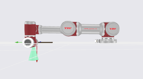
In this interface, users can set the tool orientation, defining a conical range to limit the movement of the robot's end effector within this range to avoid interference between the end effector and the robot body or external environment.
Conical Range Diagram:
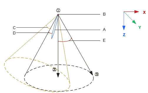
- A:End effector tool
- B:Selected coordinate system origin
- C:Tool direction offset angle, X-axis offset
- D:Safe distance
- E:Limitation range
Version 172 visualizes the user-configured cone, represented by the blue cone in the diagram below, allowing users to intuitively understand the effective restriction range.
Robot Power On:
The tool orientation limitation is active immediately after the robot powers on.
Run Start:
Enable During Operation: The tool orientation limitation is only active during program execution. It is not active during drag or manual operation modes.
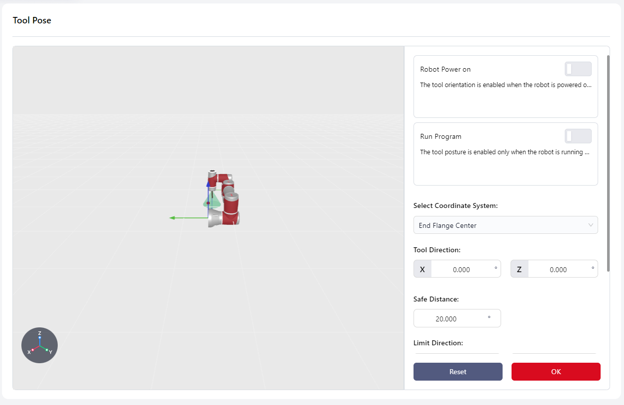
Select Coordinate System:
Determines the location of the end effector and the vertex of the cone. The coordinate system origin is the vertex.
Tool Direction:
Determines the direction of the end effector, based on the X-axis or Z-axis offset angle of the selected coordinate system.
Safe Distance:
The distance between the end effector and the defined tool boundary, ranging from 0 to the set value. When the distance is less than the safe distance, a popup will warn "Approaching Orientation Safety Limit." If the end effector reaches the boundary, the robot will stop, disable itself, and display "Exceeded Orientation Limit - Protective Stop."
Limit Direction:
Defines the location and size of the tool boundary.
- Method 1:Enter RX, RY, RZ angles directly.
- Method 2: Click Settings to enter the tool limit interface. Click the settings icon again to enter the manual operation page and determine the positions of Points 1, 2, and 3. The controller will calculate the
X Y Zvalues based on these points.
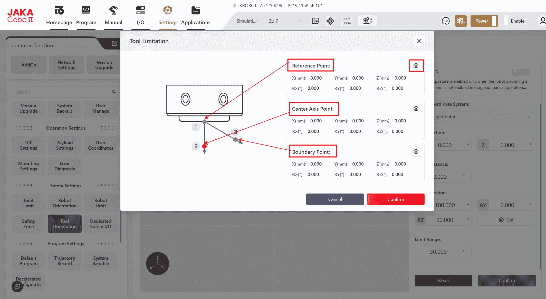
Limit Range:
Refers to the angle between the cone's centerline and its boundary, with a configurable range of 5° to 180°.
Note:
When the robot is in motion, the cone translates along the world coordinate system based on the robot's movement direction.
Dedicated Safety I/O
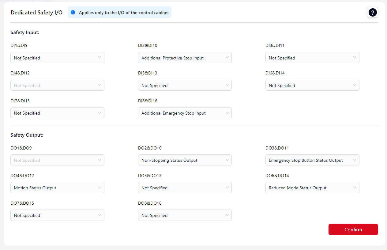
Users can configure the control cabinet panel's physical I/O to bind safety signals, turning the control cabinet's I/O into dedicated safety I/O signals to control the robot's safety actions and monitor its safety status. These dedicated safety I/O signals operate as dual-loop signals.
The standard cabinet has eight reusable safety I/O channels. All safety DI (Digital Input) channels can be configured with the same function, and all safety DO (Digital Output) channels can also be configured with the same function. The specific functions are described below:
| Name | Function | I/O Type |
|---|---|---|
| Additional Emergency Stop Input | When this input is low, the robot performs an emergency stop. | Input |
| Additional Safety Guard Stop Input | When this input is low, the robot performs a protective stop. | Input |
| Safety Guard Stop Reset Input | When the input signal changes from low to high, a protective stop reset is executed. | Input |
| Reduced Mode Input | When this input is low, the robot enters reduced mode. | Input |
| Three-Position Enable Input | This input works with a three-position switch. When in positions 1 or 3, low level, the robot performs three-position enablement restrictions. When in position 2, high level, the restriction is canceled. | Input |
| Collision Detection Off | When enabled, a rising edge signal on this input disables collision detection for the robot. | Input |
| Set Collision Sensitivity Level 1 | When enabled, a rising edge signal on this input sets the robot's collision sensitivity level to LV1. The lower the value, the higher the sensitivity. When multiple levels are triggered, the stricter level takes precedence. | Input |
| Set Collision Sensitivity Level 2 | When enabled, a rising edge signal on this input sets the robot's collision sensitivity level to LV2. The lower the value, the higher the sensitivity. When multiple levels are triggered, the stricter level takes precedence. | Input |
| Set Collision Sensitivity Level 3 | When enabled, a rising edge signal on this input sets the robot's collision sensitivity level to LV3. The lower the value, the higher the sensitivity. When multiple levels are triggered, the stricter level takes precedence. | Input |
| Set Collision Sensitivity Level 4 | When enabled, a rising edge signal on this input sets the robot's collision sensitivity level to LV4. The lower the value, the higher the sensitivity. When multiple levels are triggered, the stricter level takes precedence. | Input |
| Set Collision Sensitivity Level 5 | When enabled, a rising edge signal on this input sets the robot's collision sensitivity level to LV5. The lower the value, the higher the sensitivity. When multiple levels are triggered, the stricter level takes precedence. | Input |
| Set Collision Sensitivity to Lowest | When enabled, a rising edge signal on this input sets the robot's collision sensitivity to the lowest level. | Input |
| Emergency Stop Button Status Output | Outputs low when the emergency stop on the handle is pressed. | Output |
| System Emergency Stop Status Output | Outputs low when the system is in an emergency stop state. | Output |
| System Protective Stop Status Output | Outputs low when the system is in a protective stop state. | Output |
| Motion Status Output | Outputs low when the robot is in motion. | Output |
| Non-Stopping Status Output | Outputs high when the robot is stopped or stopping due to an emergency stop or protective stop. | Output |
| Reduced Mode Status Output | Outputs low when the robot is in reduced mode. | Output |
| Non-Reduced Mode Status Output | Outputs low when the robot is not in reduced mode. | Output |
| Collision Detection Off Output | Outputs low when collision detection is disabled. The output state is updated in real-time only after the robot is enabled. | Output |
| Collision Sensitivity Level 1 Output | Outputs low when the robot's collision sensitivity is set to LV1. The output state is updated in real-time only after the robot is enabled. | Output |
| Collision Sensitivity Level 2 Output | Outputs low when the robot's collision sensitivity is set to LV2. The output state is updated in real-time only after the robot is enabled. | Output |
| Collision Sensitivity Level 3 Output | Outputs low when the robot's collision sensitivity is set to LV3. The output state is updated in real-time only after the robot is enabled. | Output |
| Collision Sensitivity Level 4 Output | Outputs low when the robot's collision sensitivity is set to LV4. The output state is updated in real-time only after the robot is enabled. | Output |
| Collision Sensitivity Level 5 Output | Outputs low when the robot's collision sensitivity is set to LV5. The output state is updated in real-time only after the robot is enabled. | Output |
| Collision Sensitivity to Lowest Output | Outputs low when the robot's collision sensitivity is set to the lowest level. The output state is updated in real-time only after the robot is enabled. | Output |
Safety DI Signal Redundancy:
All eight channels of the safety digital input signals are redundant equivalent input signals.
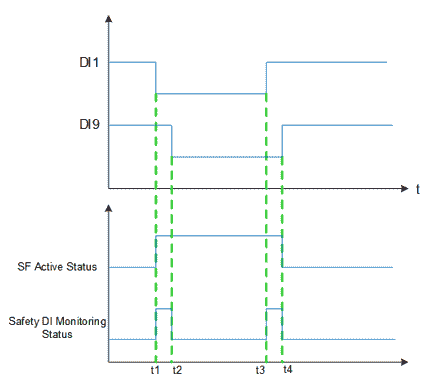
If one of the safety signals (e.g., DI1 and DI9) is low, the safety function is activated (t1). The signal used to activate the safety function must be stable; otherwise, the robot will stop, requiring a restart.
When the safety function is turned off, the robot exits the safety state, and DI1 and DI9 must both transition from low to high (rising edge) within the signal tolerance time. If there is a discrepancy between DI1 and DI9 signals, and the discrepancy lasts longer than the tolerance time of 1 second (e.g., t2-t1 or t4-t3), the SCB (Safety Control Board) will determine that a fault has occurred with the safety DI, triggering the Safety DI Fault Rollback Function.
After repair, the robot must be re-powered to clear the safety DI fault. If the fault is not cleared, the robot cannot be powered on.
Safety DI Fault Rollback Function:
- The robot decelerates to stop, powers off, and program paused.
- The faulty DI channels are processed by substituting a low-level signal for the actual input signal. This fault state persists until the robot is re-powered and the error is confirmed to be cleared.
- The interface prompts that a safety DI error has occurred. After the fault is repaired, the robot must be restarted to exit the error state.
Program Settings
Default Program
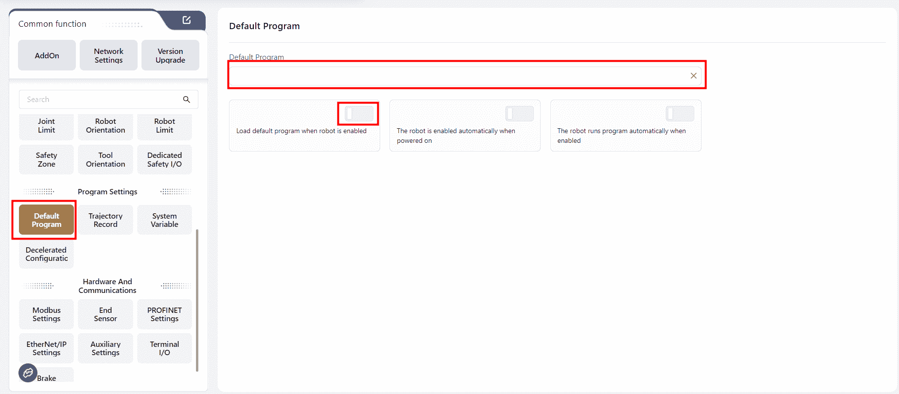
In this interface can set an existing program as the default program. Once set, the following options can be enabled to achieve specific functions:
Load Default Program when robot is enabled
When this switch is turned on, the default program is loaded automatically after the robot is enabled.
Warning:
If a default program is set, and both
Load Default Program when robot is enabled, and the signal to auto-run the program are triggered (e.g.,The robot runs program automatically when enabledis turned on), the Coboπ will run the default program.If a default program is set, and
Load Default Program when robot is enabled, is turned on, but no auto-run signal is triggered, the Coboπ will not run any program.If a default program is set, but
Load Default Program when robot is enabled, is not turned on, and an auto-run signal is triggered, the Coboπ will display an error popup.If no default program is set, but
Load Default Program when robot is enabled, is turned on, and an auto-run signal is triggered, the Coboπ will display an error popup.If a default program is set, and both
Load Default Program when robot is enabled, and an auto-run signal are triggered while another non-default program is open, the default program will be run.
The controller will check in the background whether there are unsaved changes in the currently open program. If there are unsaved changes, the programming interface will be gray, displaying the currently open program, and a popup will prompt "Unsaved Changes in Current Program, Please Confirm After Stopping the Program."
If all changes have been saved, it will directly switch to the default program.
The robot is enabled automatically when powered on
When this switch is turned on, the robot will automatically be enabled after powered on.
The robot runs program automatically when enabled
When this switch is turned on, the robot will automatically run the set default program or the currently open program after being enabled.
If no default program is set, the currently open program will be run;
If a default program is set and Load Default Program when robot is enabled is turned on, the default program will be run.
Trajectory Recording
In this interface, the controller can record the robot's trajectory through drag-and-drop, manual operations, or other methods, and generate a trajectory file.
The current trajectory can also be recorded while the robot is executing a program.
During programming, the recorded trajectory files can be invoked using trajectory recording commands.
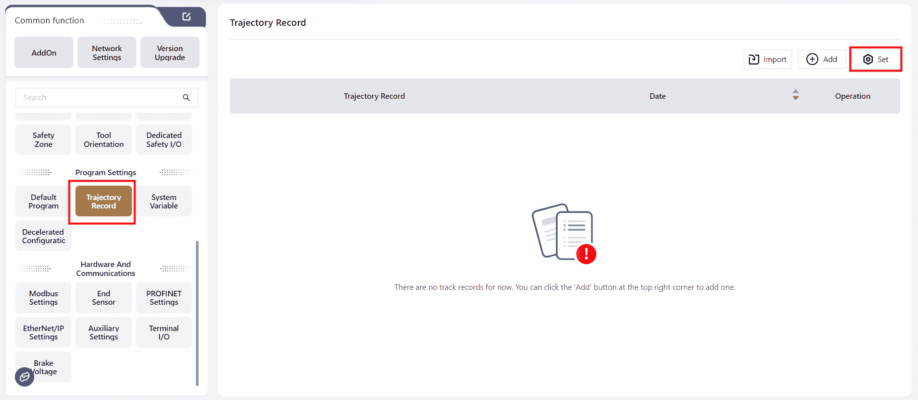
- Click
Setto open the trajectory movement editing interface.
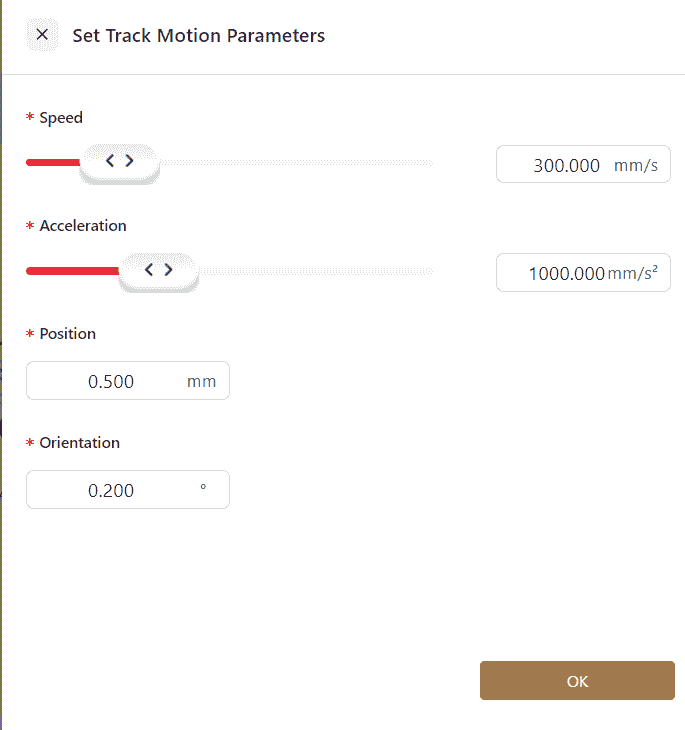
Note:
If the change in the trajectory's position or orientation is less than ten times the accuracy of the set position or orientation, the trajectory cannot be generated.
Therefore, when the movement distance of the trajectory is short, it is recommended to increase the accuracy of the position and orientation to 0.1.
- Click
Addto bring up a confirmation window, then clickOK.
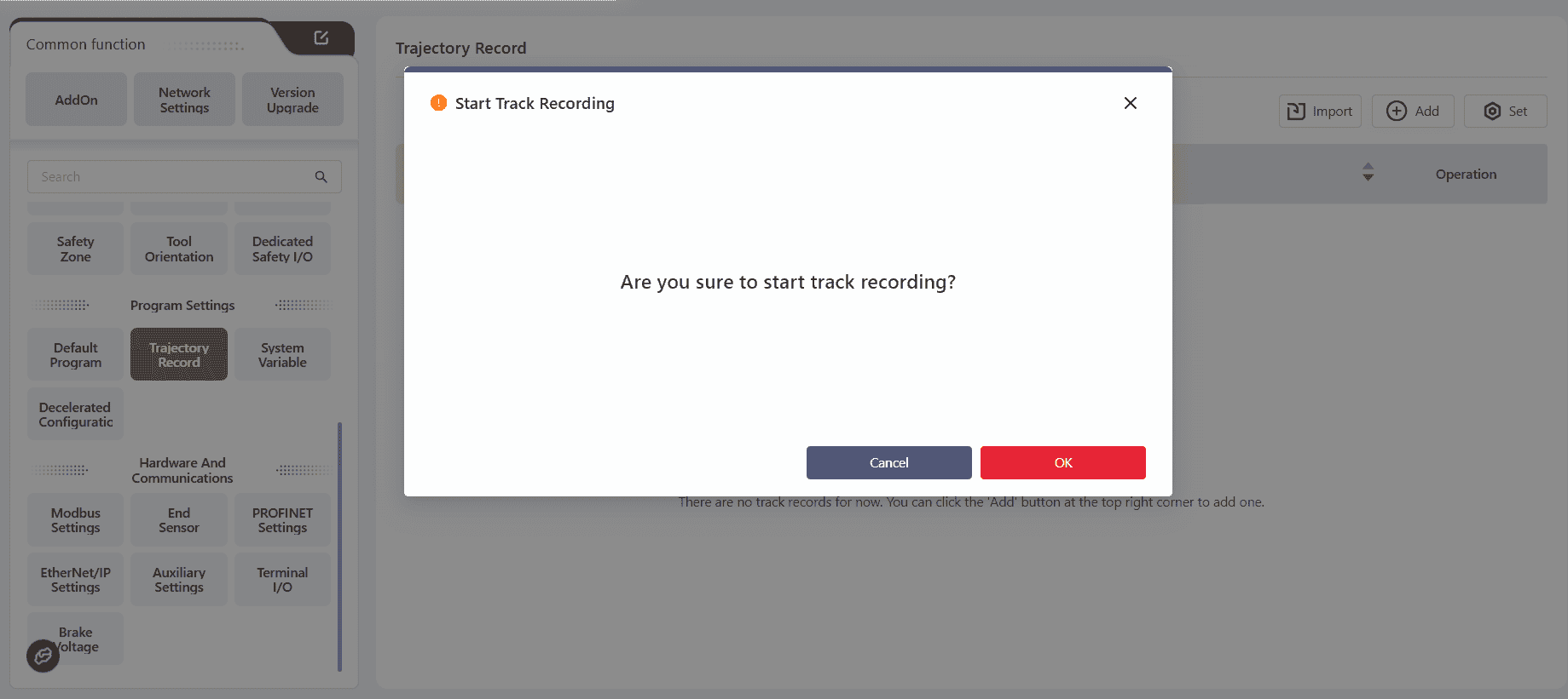
At this point, the page will indicate that the trajectory is being recorded.
Use drag mode or manual operations to make the robot perform the desired actions.
After completing the motion teaching, click the S-shaped trajectory recording button in the top navigation bar to stop recording. The interface will then generate a trajectory file.
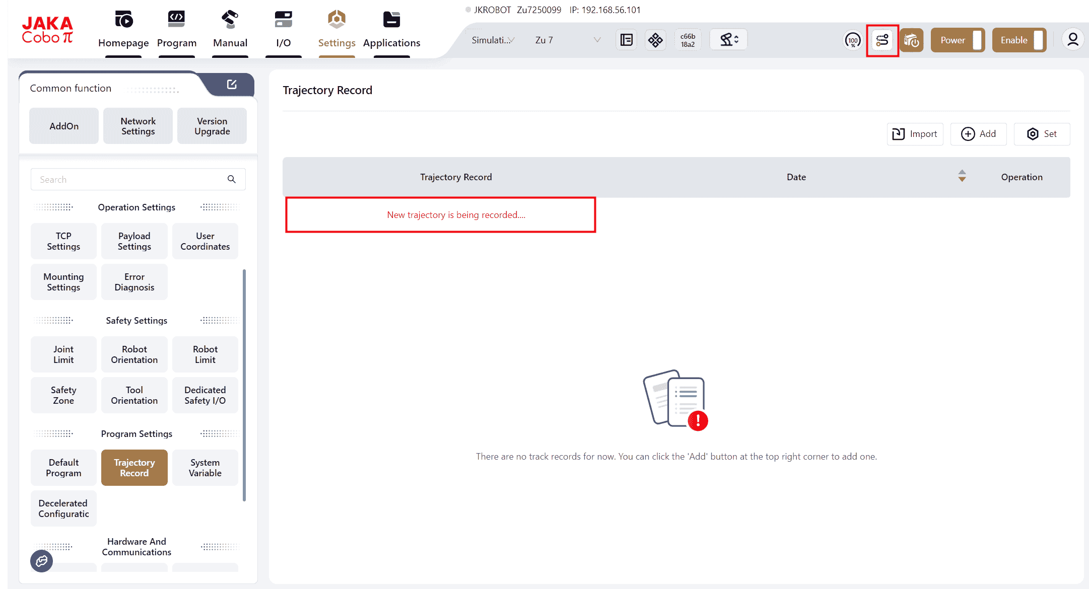
- Click on the icons to perform the corresponding operations.
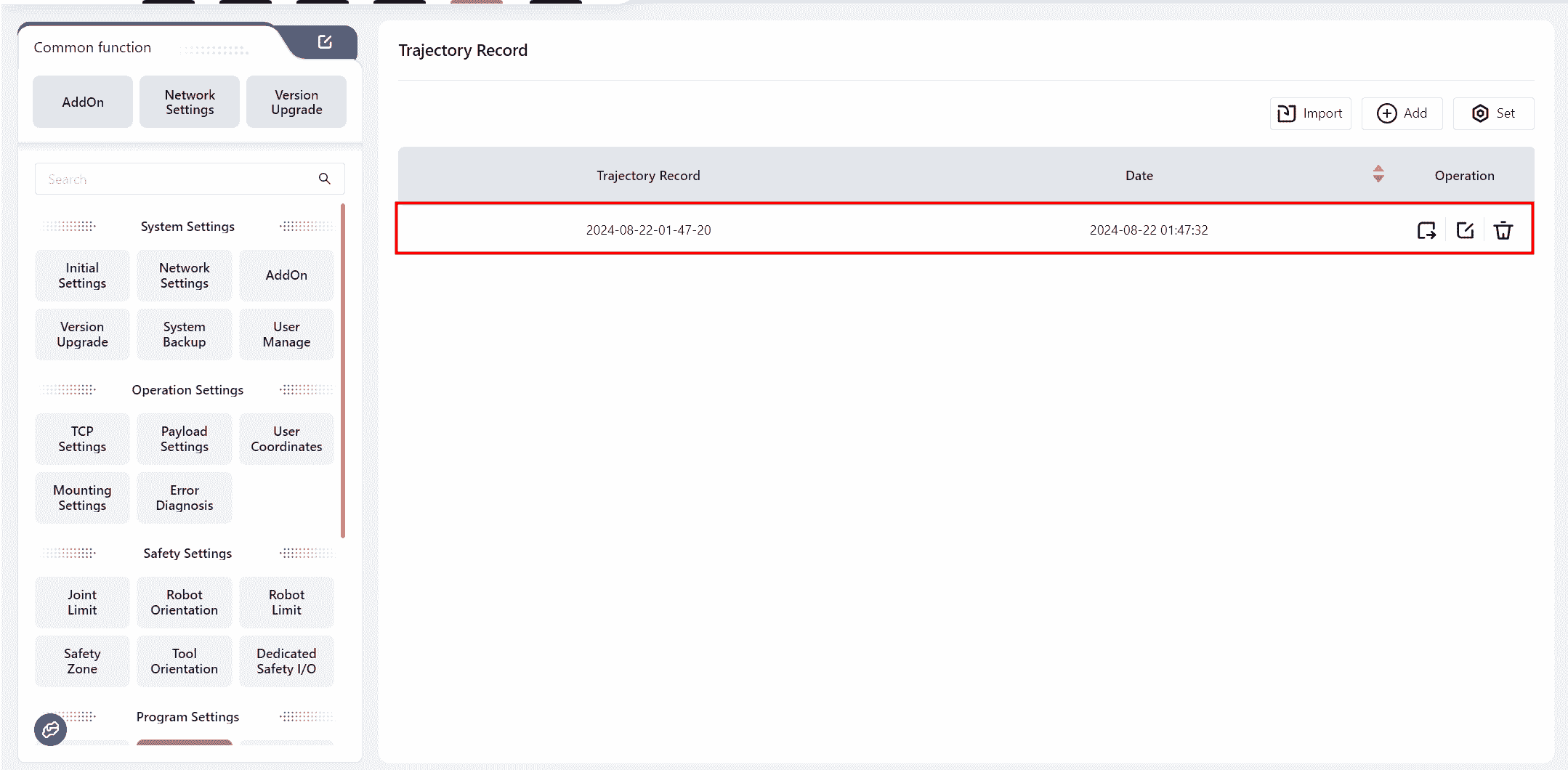
Note:
- 5 trajectory files can be imported and exported at the same time at most.
- The trajectory recording command can be called in the programming control interface to represent the trajectory.
- The trajectory representation function only records path information, not speed information.
- Stationary states do not repeat point recording.
- If recording is not manually stopped, it will automatically end after sampling 100,000 points, generating a trajectory file.
System Variables
This interface allows for the creation of system variables that can be used across all programs.
System variables are stored independently in the controller and can only be numerical (range: -65535~65535). They can be called and modified in any program.
The values of these variables do not change or reset when the program starts or stops, when the robot is powered on or off, or when the control cabinet is shut down.
Click Add to enter the variable editing interface.
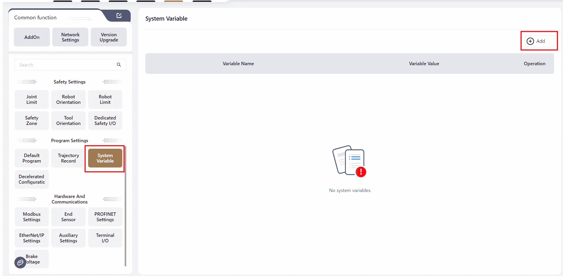
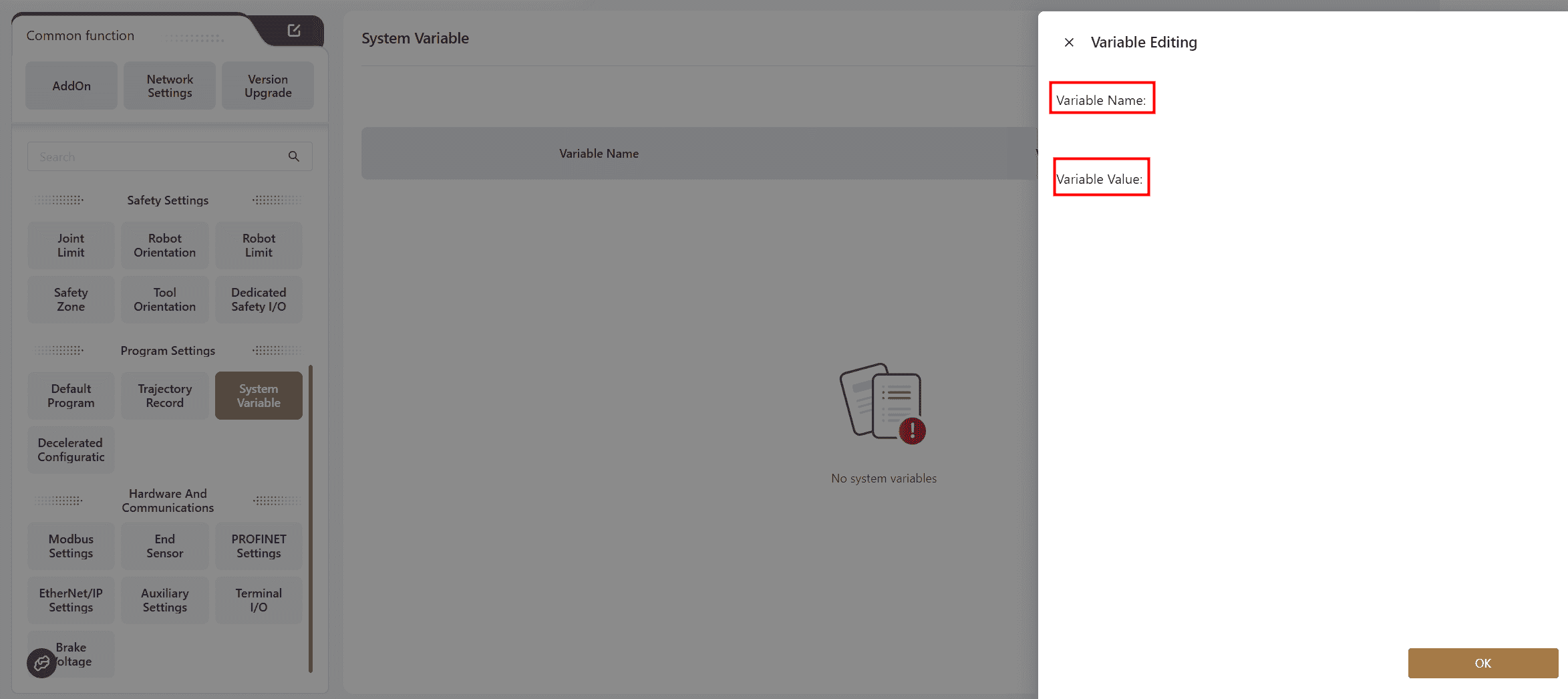
After editing is completed, the newly added variables will be displayed in the interface.
You can click on the icons on the right to perform corresponding operations.
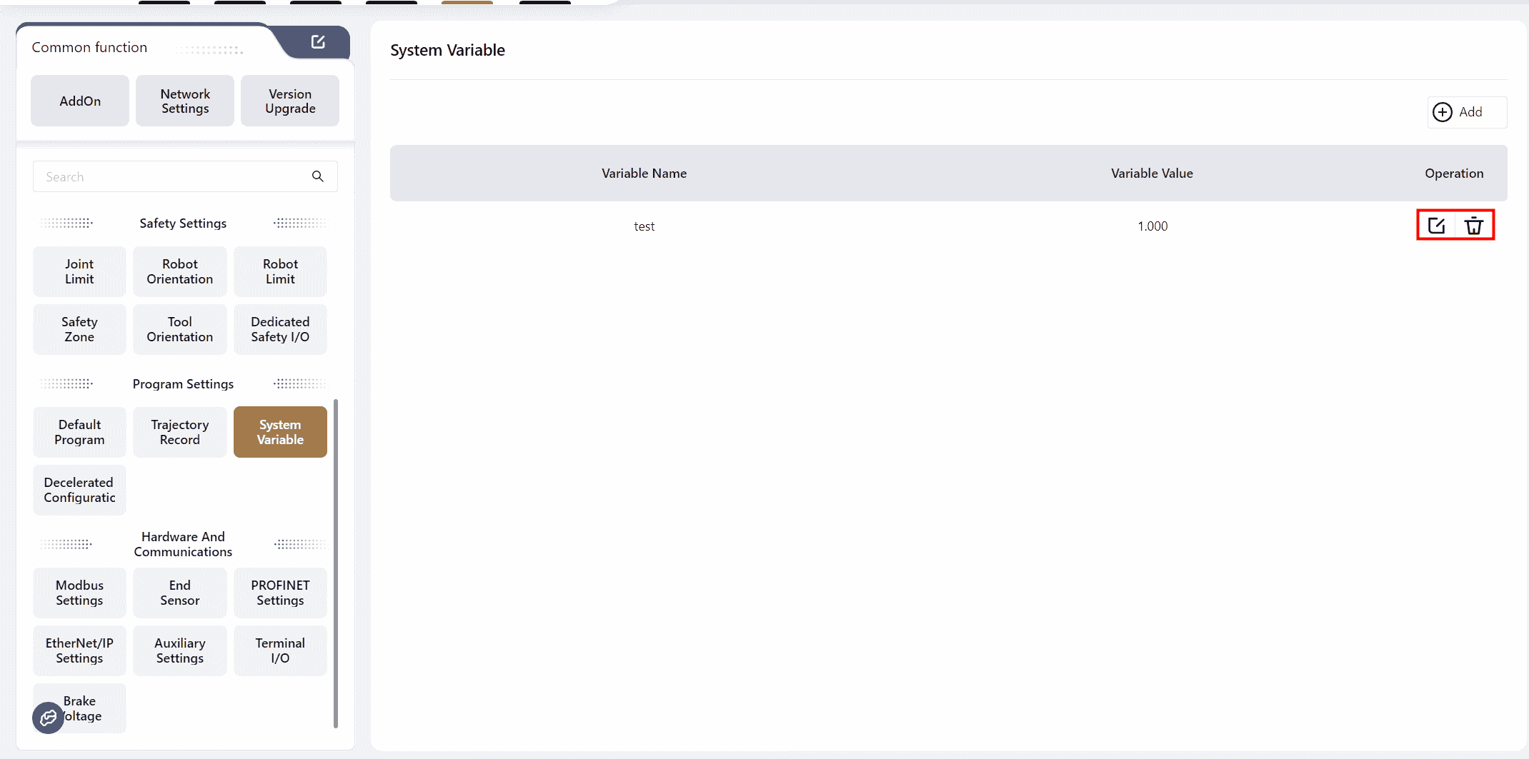
Note:
Up to 100 system variables can be stored.
New system variables can also be created in the variable command bar of the programming control interface.
Decelerated Speed Configuration
The decelerated speed configuration is used to adjust the robot's movement speed during program execution. The configuration method is shown below:
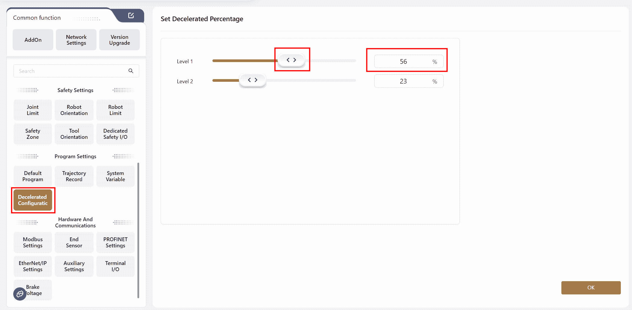
Warning:
The level 2 decelerated speed value should be less than the level 1 decelerated speed value.
Note:
After completing the configuration in this interface, the I/O Panel must be used to configure DI into level 1 or level 2 decelerated speed mode to trigger the function.
If both level 1 and level 2 decelerated speed are configured, the level 2 decelerated speed will take precedence.
The decelerated speed setting only takes effect during program execution and does not apply in drag or JOG modes.
Once the settings are successfully applied, the robot will operate at the configured speed during program execution.
For example, if the level 1 decelerated speed is set to 55%, the speed displayed in the programming interface will be 55%, and the robot will move at this speed.
Hardware and Communication
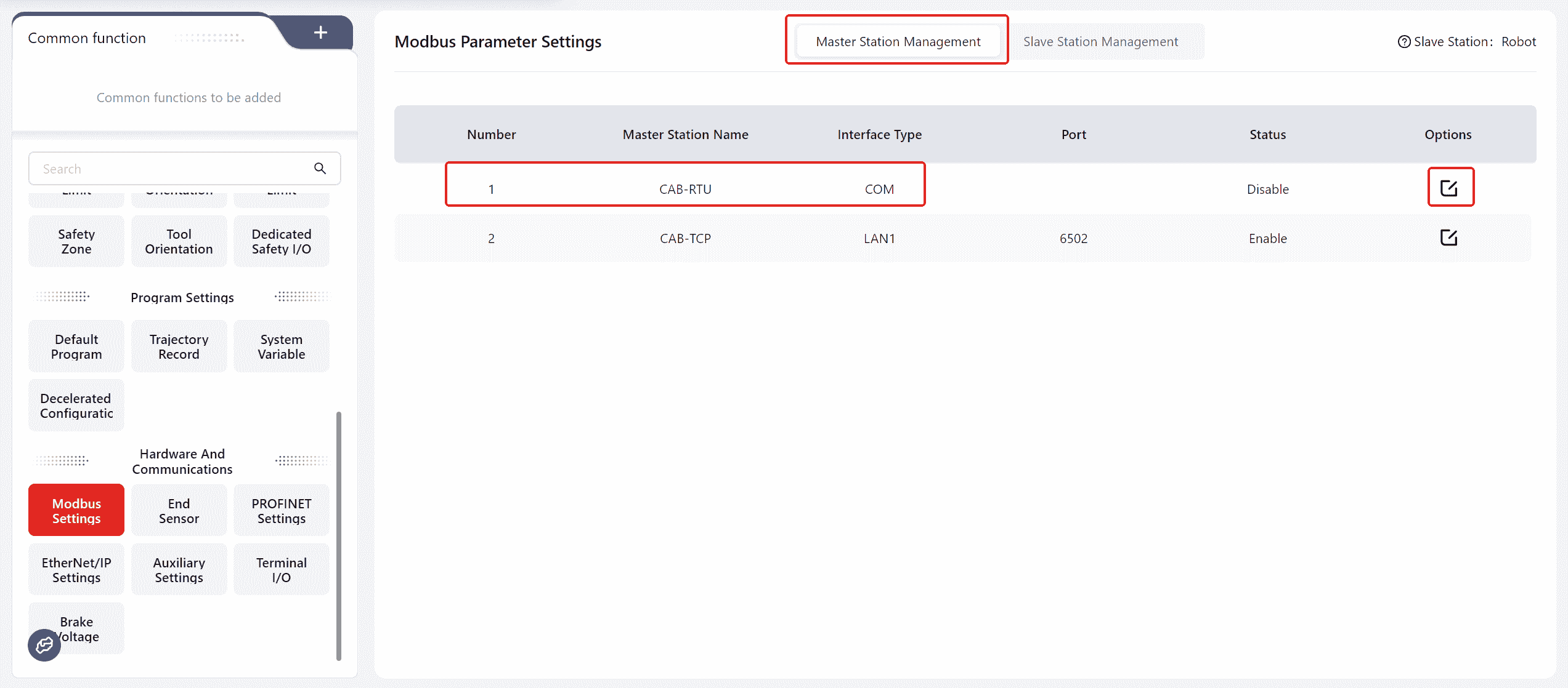
Modbus Settings
Coboπ supports both Modbus TCP/IP and Modbus RTU communication protocols, with the robot functioning as a slave device.
Warning:
When configuring settings, ensure that the robot is in a powered-off and disabled state.
Note:
Configuration for when the robot acts as the master device can also be done on this page. For detailed instructions, refer to:Extended I/O, Robot as Master
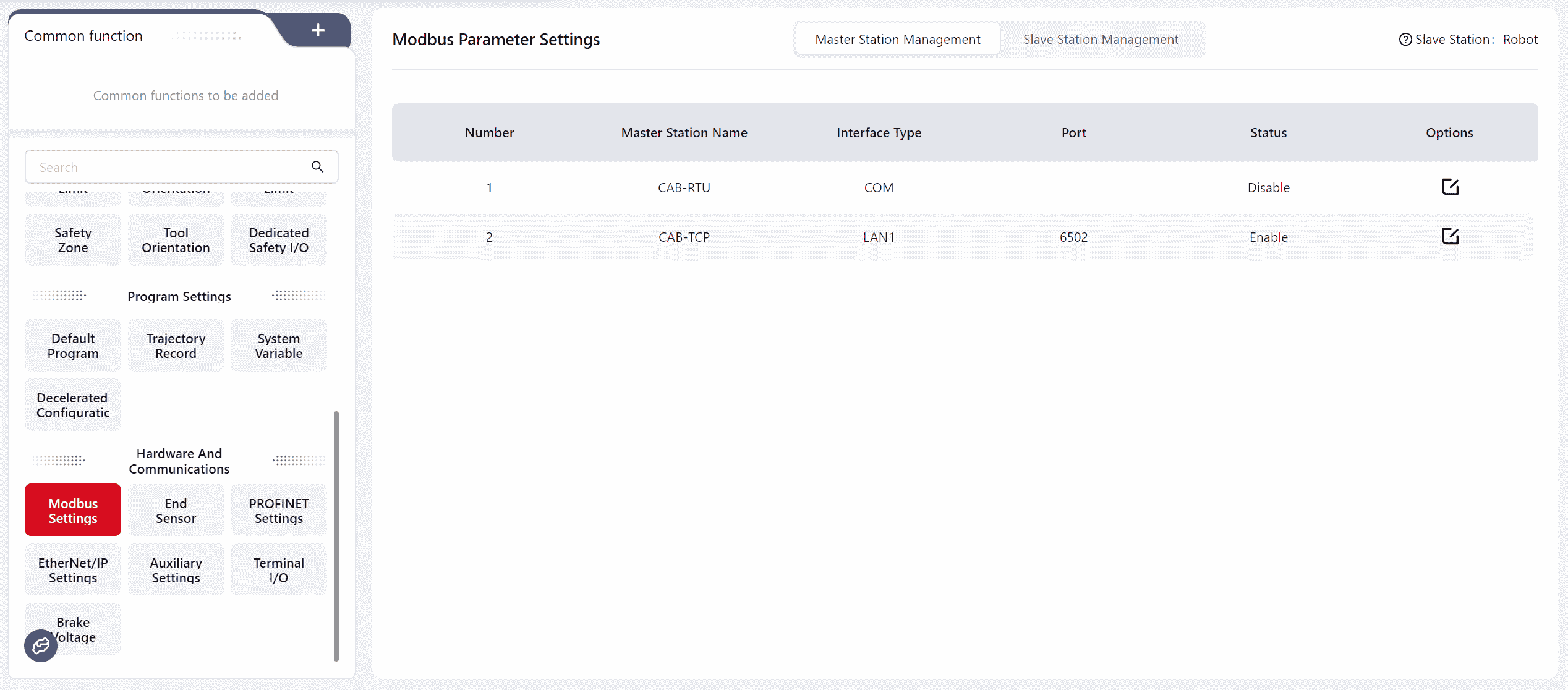
Modbus RTU
Warning:
This feature requires customization.
- For a standard cabinet, connect to the RS485 interface on the front panel of the control cabinet.
- For a MiniCab, connect to the PIN19 and PIN20 I/O interface on the front panel of the control cabinet. Refer to the hardware user manual for the interface location and wiring method.
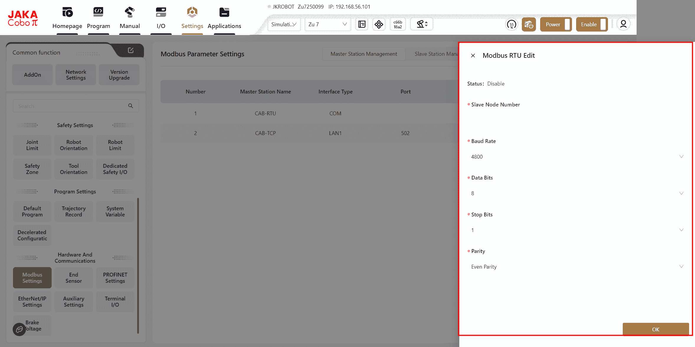
- In
Modbus SettingsselectMaster Station Management-CAB-RTU. After clicking the edit icon, the specific operation page will appear. Input the slave node number, selectBaud Rate, Data Bits, Stop Bits, Parity, then clickOK. - Once the settings are successfully applied, power off the control cabinet, restart it, and reconnect the robot to make the settings effective.
- After establishing a connection with the master device, programs can be written to read the robot's status or control the robot's I/O signals based on the register addresses and function codes in the Modbus address table. This can also be viewed under
I/O Panel-Modbus.
Modbus TCP/IP
- When using a standard cabinet, connect to the network port at the bottom of the control cabinet.
- When using the MiniCab, connect to the LAN2 port. Refer to the hardware user manual for the port location.
- In
Modbus Settings, selectMaster Station Management-CAB-TCP. After clicking the edit icon, you will be redirected to a specific operation page. Enter the port number in the Port field (range: 0-65535, default port number: 6502), and clickOK.
Warning:
Please avoid using commonly used service ports, such as 8080, 80, etc.
- After the settings are successfully configured, power off the control cabinet, restart it, and reconnect the robot to apply the settings.
- Once the connection with the master is established, it is necessary to write a program to read the robot's status or control the robot's I/O signals based on the register addresses and function codes in the Modbus address table. The status can also be viewed in the
I/O Panel-Modbussection.
End Sensor
If the JAKA force control product is being used, it can be configured on this interface.
For detailed operations, refer to the JAKA Force Control Product User Manual.
Warning
Max Force Limitdoes not take effect in Freedrive mode.
Optional force control products can be configured on this page. For detailed operation, refer to the JAKA Force Control Product User Manual.
Sensor Configuration

- Sensor Status: Displays and controls the sensor's status. The sensor automatically powers on when the robot is powered on. When the switch is on, the sensor is in normal operation. Clicking the switch manually turns it off. When the switch is off, the sensor is off, and clicking the switch manually turns it on. When the switch shows "Editing" the system is attempting to start the sensor automatically in the background. This typically occurs during robot startup or after an unexpected sensor disconnection. The auto-start process usually takes 4-6 seconds, during which the switch cannot be clicked. Please wait for the sensor to restart. If auto-start fails, try turning the sensor on manually or rebooting the robot. If the sensor still cannot be started, contact JAKA technical support. Do not disassemble or repair it without authorization.
- Sensor Zeroing: Click the icon to zero the sensor. Ensure that the robot's end-effector is free from any external force and that the robot is not in tool drag or constant-force compliance mode while zeroing. It is recommended to zero the sensor before each use to maintain measurement accuracy. Sensor zeroing can also be performed in the force value display interface.
Note:
Due to factory offset and temperature effects, even if no external force is applied to the sensor, its readings may not be zero. A deviation within 20N or 2Nm is normal and does not indicate a sensor quality issue. After zeroing, the sensor can function normally. If the sensor's raw readings exceed 20N or 2Nm when no external force is applied and the robot flange is unmounted, please contact JAKA technical support for inspection.
Warning:
Sensor zeroing takes approximately 1 second. During this time, the black rubber ring below the robot flange must not experience any force other than the weight of the end-effector itself. This includes but is not limited to collisions, compressions, or touches. Failure to comply may result in sensor compensation errors, leading to uncontrolled robot movement, equipment damage, or personal injury!
After equipment installation, robot restart, fault recovery, or prolonged sensor operation, you must zero the sensor before using any force control functions. Failing to do so may result in uncontrolled robot movement, equipment damage, or personal injury!
- Real-Time Force Display: Click the button to navigate to the monitoring interface, displaying the sensor's current force data.
- Maximum Force Limit: Sets the maximum force and torque limits for the sensor in the X, Y, Z directions. If the detected force exceeds the set limit, the robot stops immediately and triggers a collision alarm. The force limit is inactive unless the sensor is zeroed. A force limit value of 0 automatically uses the sensor's default maximum range. For sensor range details, refer to the JAKA S Series Hardware User Manual.
- Sensor Sensitivity: Specifies the minimum external force and torque the sensor can detect. If the sensor readings exceed the set sensitivity value, the excess is considered the measured force. If the readings are below the set value, the sensor is deemed unaffected by external force. Sensor sensitivity settings impact all force control functions. For example, a smaller sensitivity value reduces the force required for tool drag mode, increases detection sensitivity for maximum force limits and termination conditions, and decreases target force errors in constant-force compliance mode. If "Independent Direction Configuration" is selected, sensitivity can be configured for each direction independently. Otherwise, only the Fx direction can be configured, and other directions change accordingly.
Note:
The sensor is a precision measuring component susceptible to environmental interference, causing slight zero-point drift during operation. Even after correct zeroing, factors like temperature changes or robot posture adjustments can result in small zero-point variations (within 0.5% of the sensor range). This may cause non-zero readings (approximately 1-2N) without external force. Adjust the sensor sensitivity as needed to counteract this effect.
Data Smoothing: Filters out signals above the set frequency to smooth the force value curve. A value of 0 disables smoothing. Lower values result in more filtering, smoother force curves, and reduced sensitivity to force changes. For general scenarios, set values between 20Hz and 60Hz. This feature is typically used for tasks like grinding, where external vibrations cause force fluctuations.
Advanced Feature Configuration
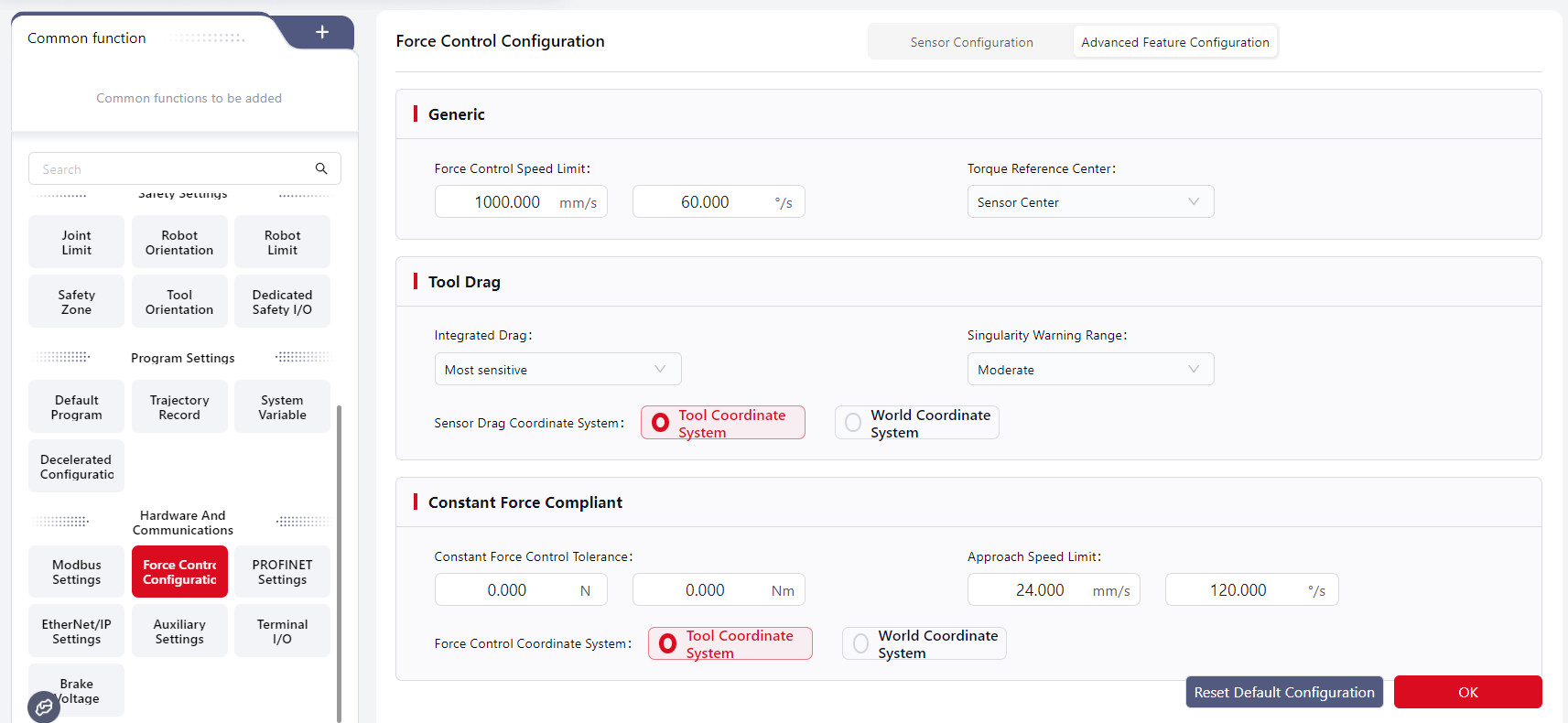
- Force-Controlled Speed Limit: In tool drag mode, limits the TCP speed. In constant-force compliance mode, restricts the difference between the robot's actual and command speeds. When the actual speed reaches the limit, the robot maintains that speed. Default: 500mm/s, 60°/s.
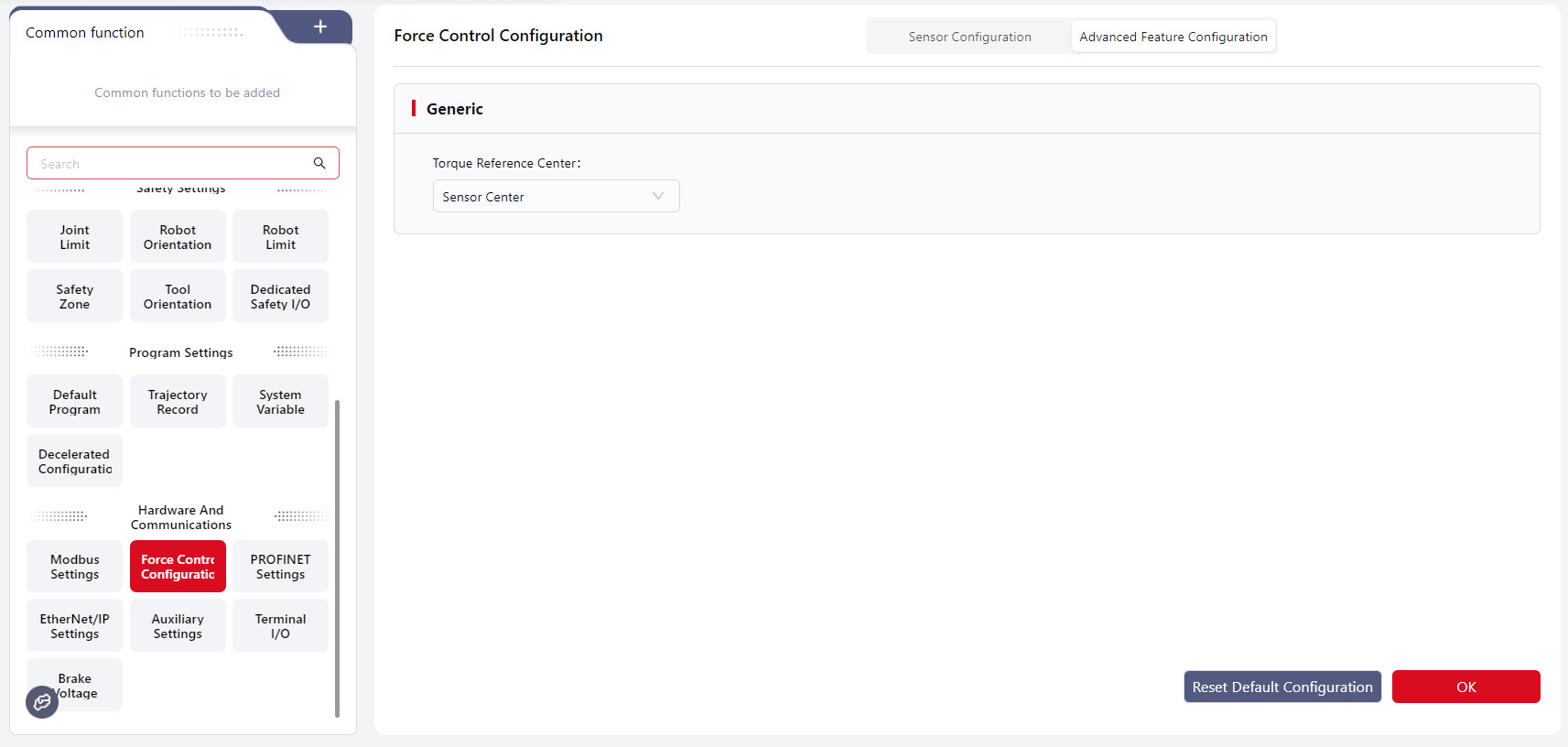
- Torque Reference Center: The point used to calculate torque generated by external force. The distance between the actual force application and this center point determines the torque arm. It impacts robot rotation direction and speed under external force, termination conditions, and maximum torque limits. Options: Sensor Center Point Or TCP (default: Sensor Center Point).
- Hybrid Drag: When enabled, allows dragging the robot body to move it in Cartesian space during tool drag mode. Tool drag settings apply to hybrid drag as well. The more sensitive the hybrid drag level, the less force is required. Default: Disabled.
- Drag Singular Point Warning Range: The robot's distance from singular points to trigger a warning in tool drag mode. A larger range triggers warnings farther from singular points. Default: Moderate range.
- Drag Coordinate System: The reference coordinate system for tool drag mode.
- Constant Force Control Tolerance: The maximum difference allowed between actual contact force feedback and target force in constant-force compliance mode. Within this range, the robot considers the target force achieved and stops adjusting. Default: 0.
- Approach Speed Limit: In constant-force compliance mode, restricts the difference between TCP actual and command speeds before the force value reaches the sensor sensitivity threshold. When the difference reaches this limit, the robot maintains the speed. Default: 10mm/s, 1°/s.
- Force Control Coordinate System: The reference coordinate system for all force control functions except tool drag mode.
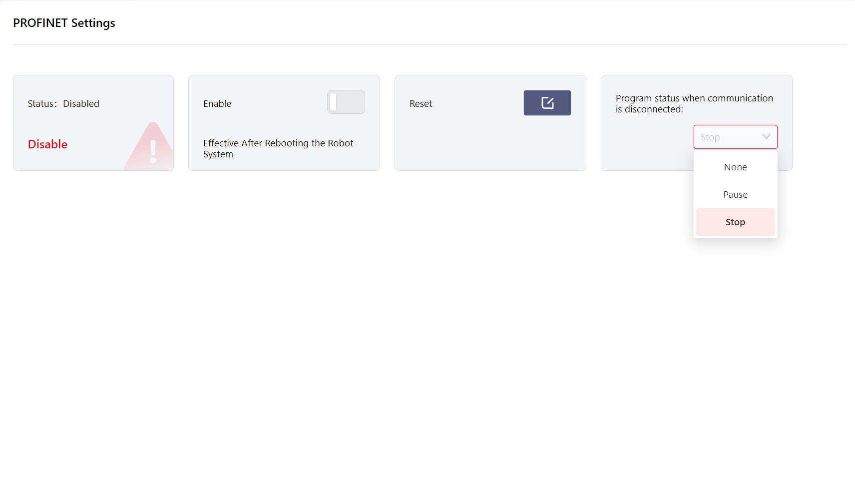
PROFINET Settings
JAKA robots support the PROFINET communication protocol, allowing them to act as a PROFINET slave and connect with external devices.
After connecting to the network port at the bottom of the control cabinet, enter this page and enable the PROFINET function. Once enabled, restart the control cabinet to apply the changes. After activation, PROFINET can interact with external PLCs, and its I/O information will be displayed in the I/O Panel - Fixed I/O section.
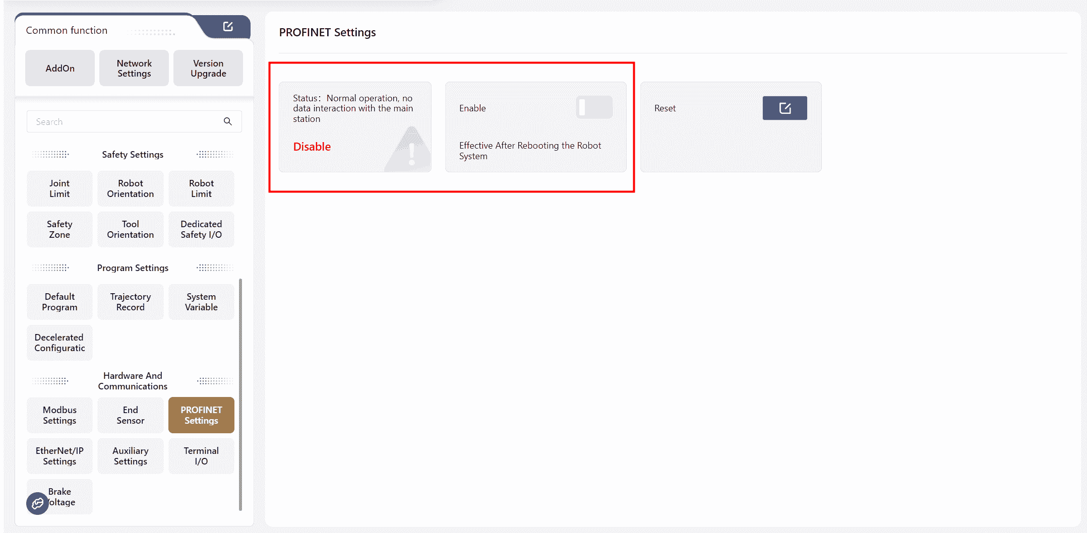
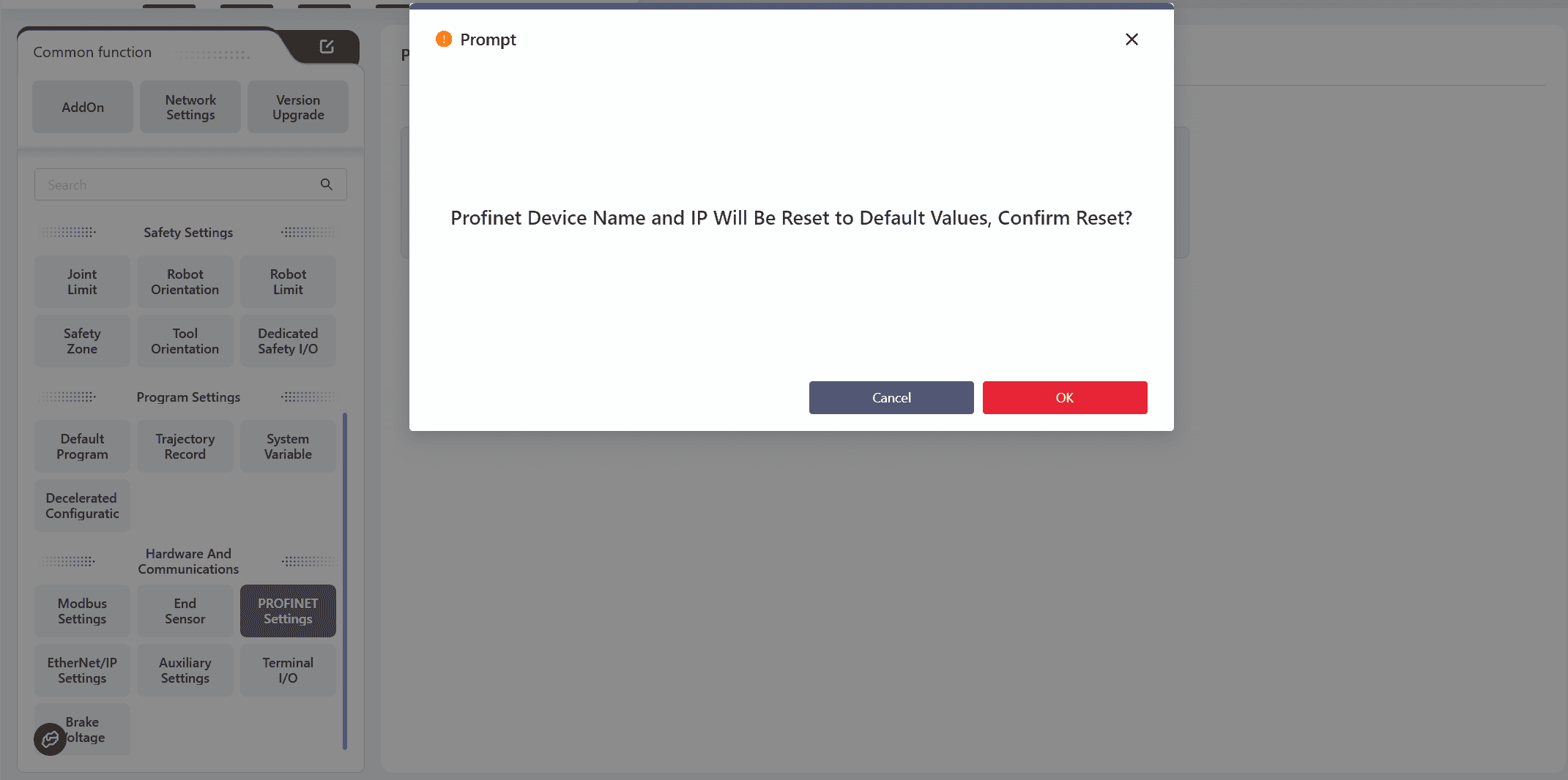
Clicking Reset will restore the PROFINET device's communication configuration on the PLC side, including name, IP address, enable status, etc.
The default name is: jaka;
The default IP address is: 192.168.0.50.
For details on using PROFINET I/O, see: PROFINET I/O
For details of the PROFINET address table, see: PROFINET I/O Address Table
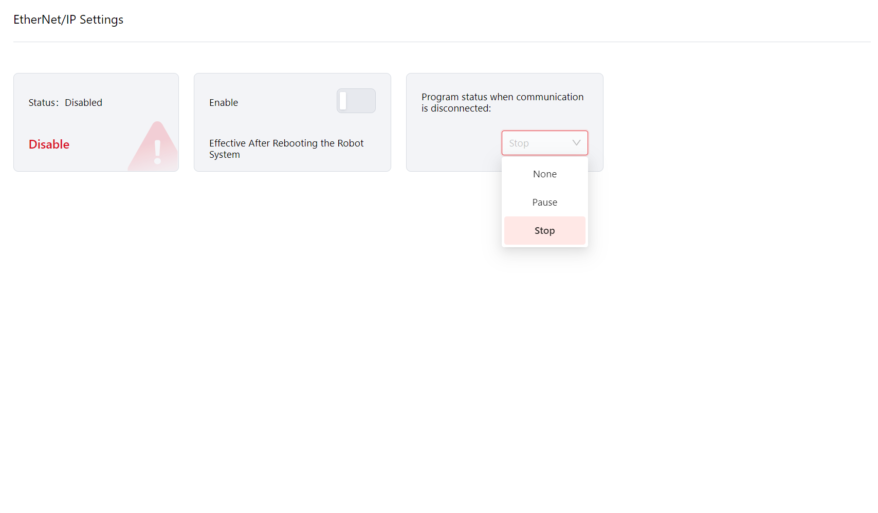
In Version 172, users can configure the program's behavior when communication is interrupted, with the following options: None, Pause, or Stop.
- None: The program does not take any specific action and continues running in its current state.
- Pause: The program pauses and resumes from the pause point once communication is restored.
- Stop: The program stops and restarts from the beginning when communication is restored.
In version 172, users can download file directly: 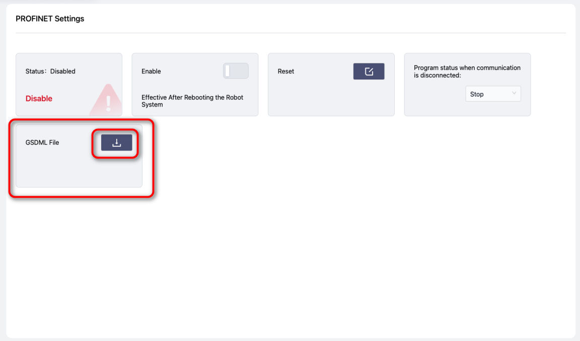
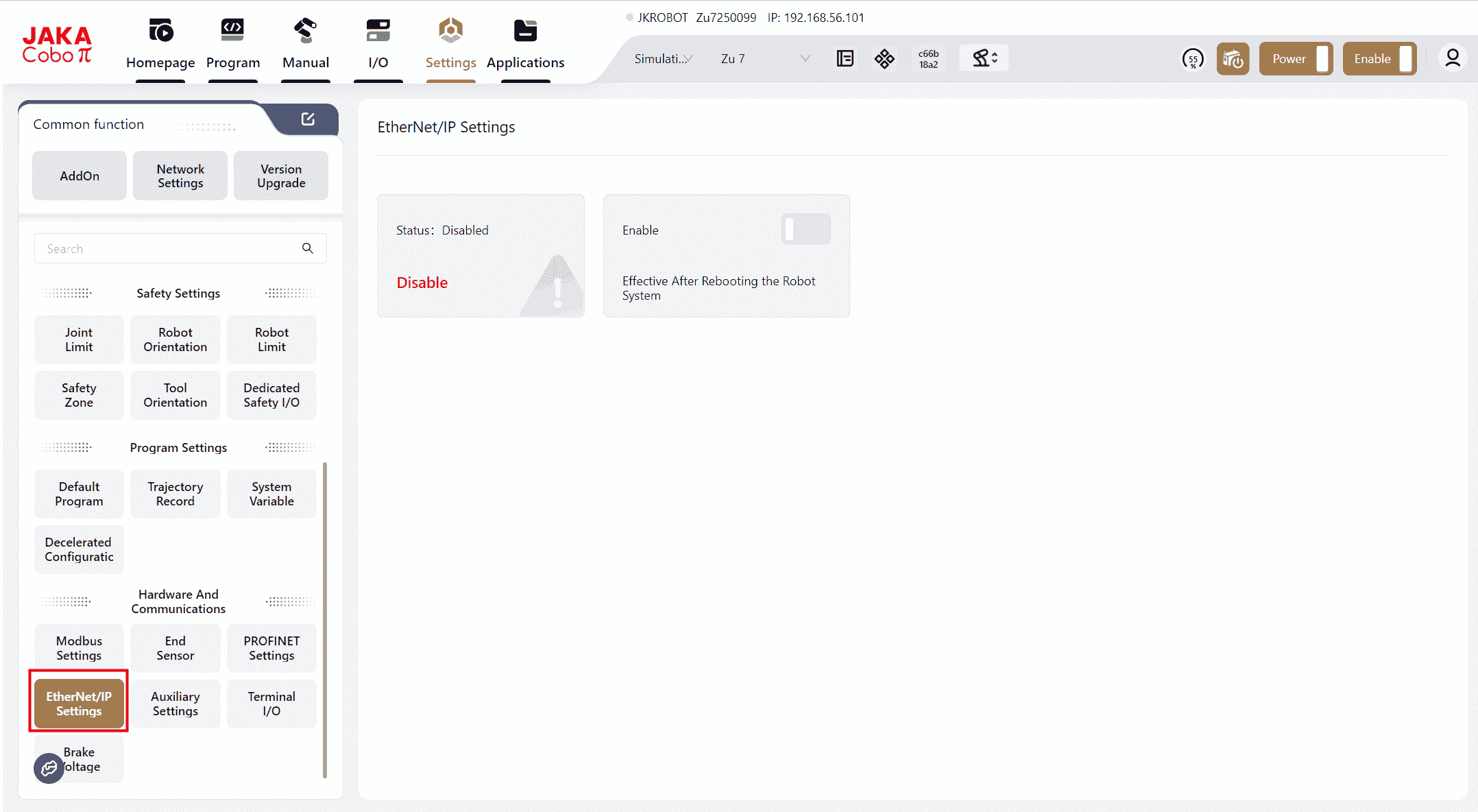
EtherNet/IP Settings
JAKA robots support the EtherNet/IP communication protocol, allowing them to act as an EtherNet/IP slave and connect with external devices.
After connecting to the network port at the bottom of the control cabinet, enter this page and enable the EtherNet/IP function. Once enabled, restart the control cabinet to apply the changes. After activation, EtherNet/IP can communicate with external PLCs, and its I/O information will be displayed in the I/O Panel - Fixed I/O section.
In Version 172, users can configure the program's behavior when communication is interrupted, with the follow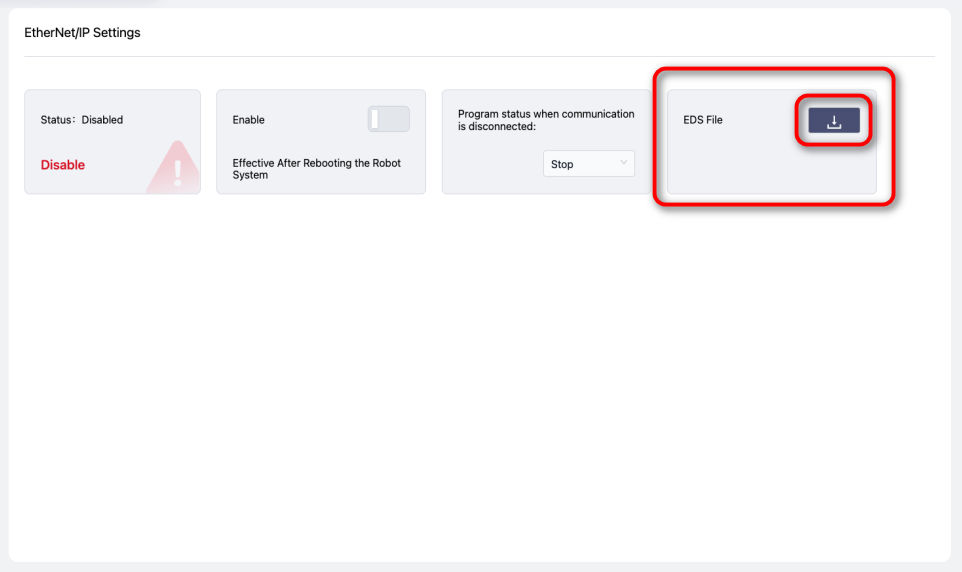 ing options: None, Pause, or Stop.
- None: The program does not take any specific action and continues running in its current state.
- Pause: The program pauses and resumes from the pause point once communication is restored.
- Stop: The program stops and restarts from the beginning when communication is restored.
In version 172, users can download file directly:
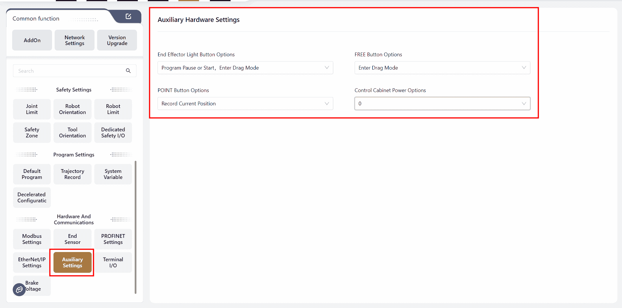
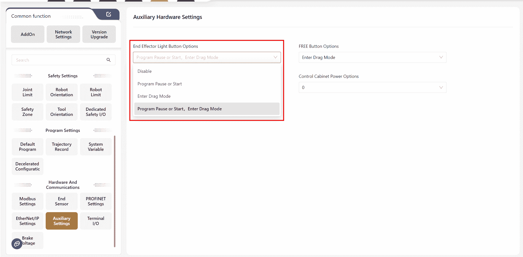
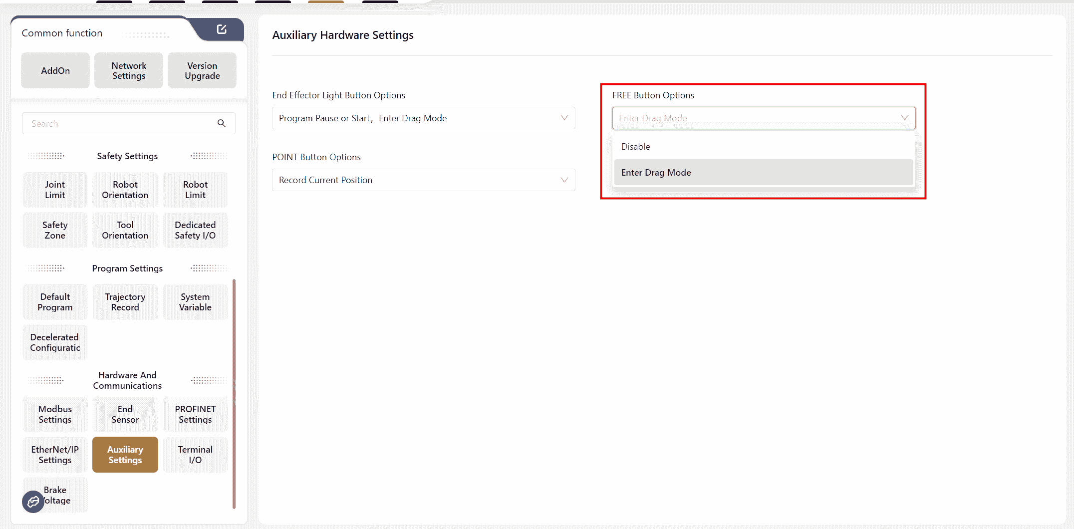
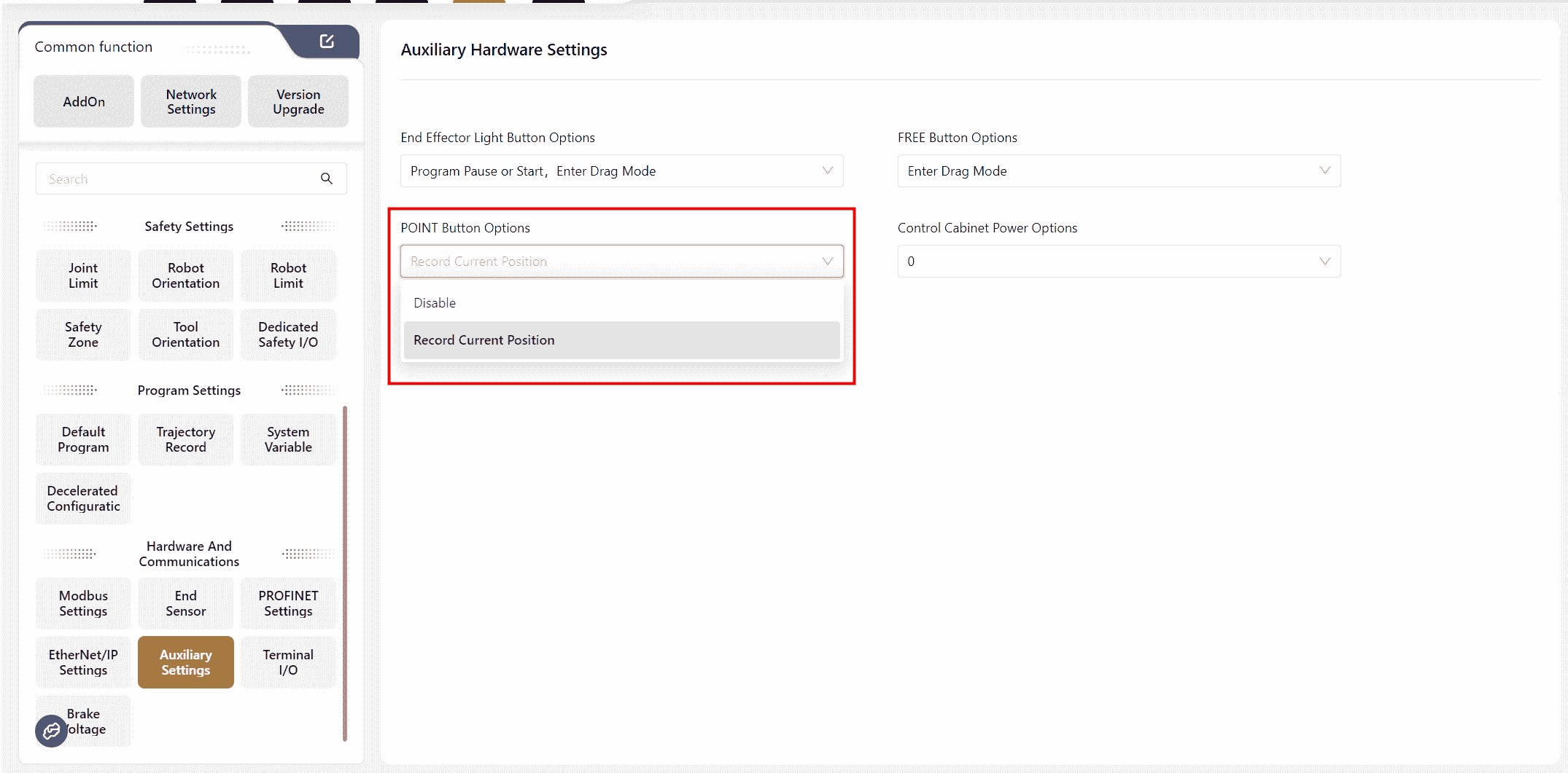
Auxiliary Hardware Settings
The JAKA robot's end features three buttons: End Effector Light Button Options FREE Button Options POINT Button Options .Their functions and the control cabinet's power supply voltage can be configured on this interface.
End Light Button
FREE Button
POINT Button
Control Cabinet Power Options
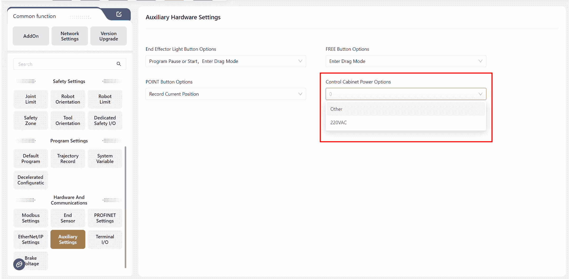
This feature is used to configure the control cabinet's power supply voltage. If the control cabinet's power supply environment is not 220VAC, the power supply option must be adjusted. The SCB version is required to be version 02_57 or higher.
Note:
Disabling the function means turning it off; by default, the function is enabled.
Pressing and holding the FREE button will enter drag mode.
Pressing and releasing the FREE button can pause and start the program, as well as record the current position.
The robot cannot enter drag mode when the program is paused or running.
If the End Light Button is not disabled, it can be pressed to clear collision alarms after a collision.
In Version 172, this interface distinguishes between two types of settings:Function Settings and Light Settings
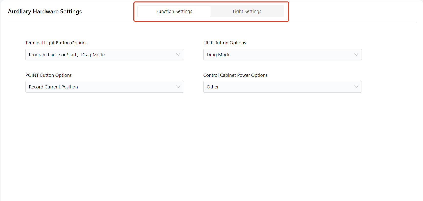
- Function Settings: The functions and configuration methods remain the same as in previous versions. However, if you are using an S-series robot, specific features unique to the S-series can be configured here:
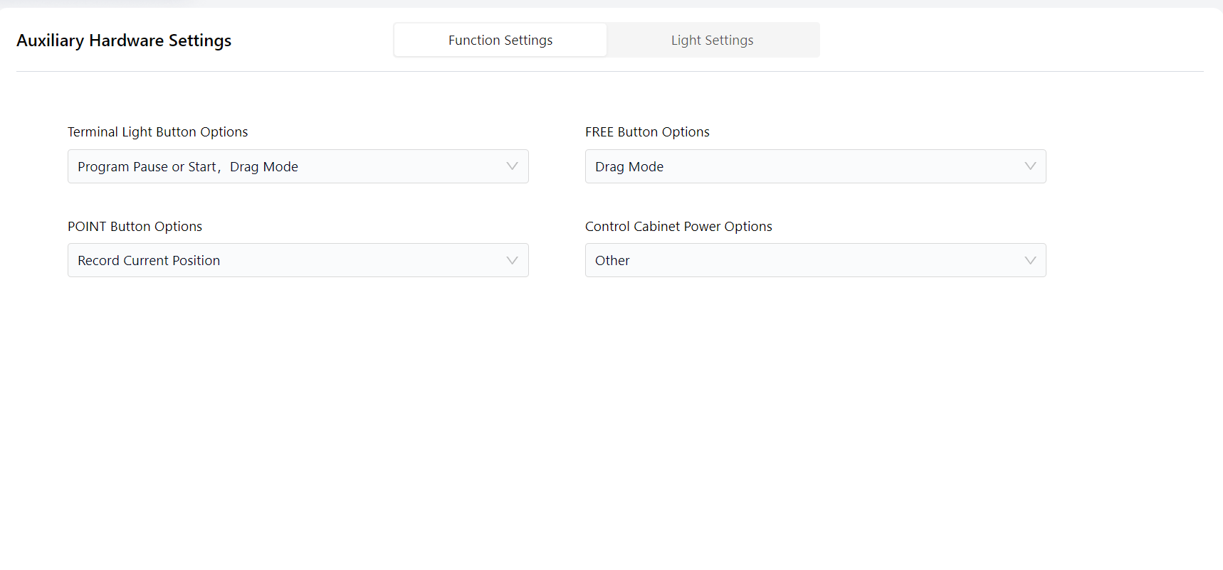
- Light Settings: On this page, you can configure the color of the end effector's breathing light to indicate different robot states:
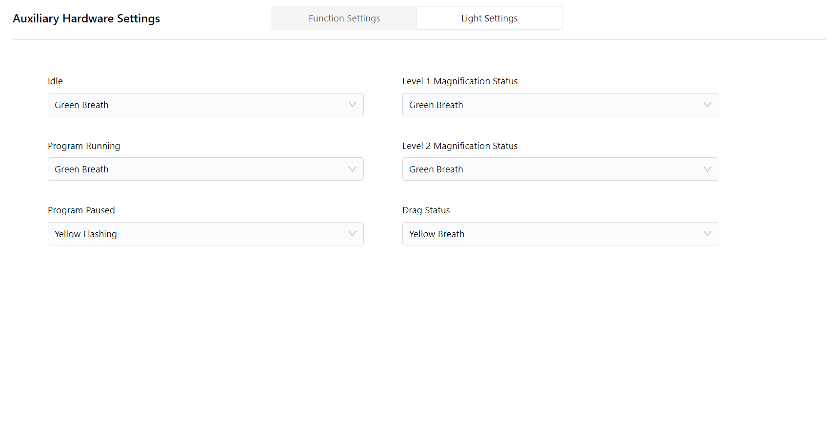
Difference:
- When the light is
Flashing, the brightness changes rapidly and intensely. - When the light is
Breathing, the brightness changes slowly and smoothly.
Terminal I/O
Warning:
This feature is only applicable to TIO Version 3.
The robot's end is equipped with a small I/O interface (TIO), which supports 2 digital inputs, 2 digital outputs, and 2 analog inputs. The 2 digital outputs can be repurposed as a high-speed RS485 channel, and the 2 analog inputs can be repurposed as a low-speed RS485 channel. Additionally, it supports configurable voltage output (12V/24V/OFF) to power external extended devices.
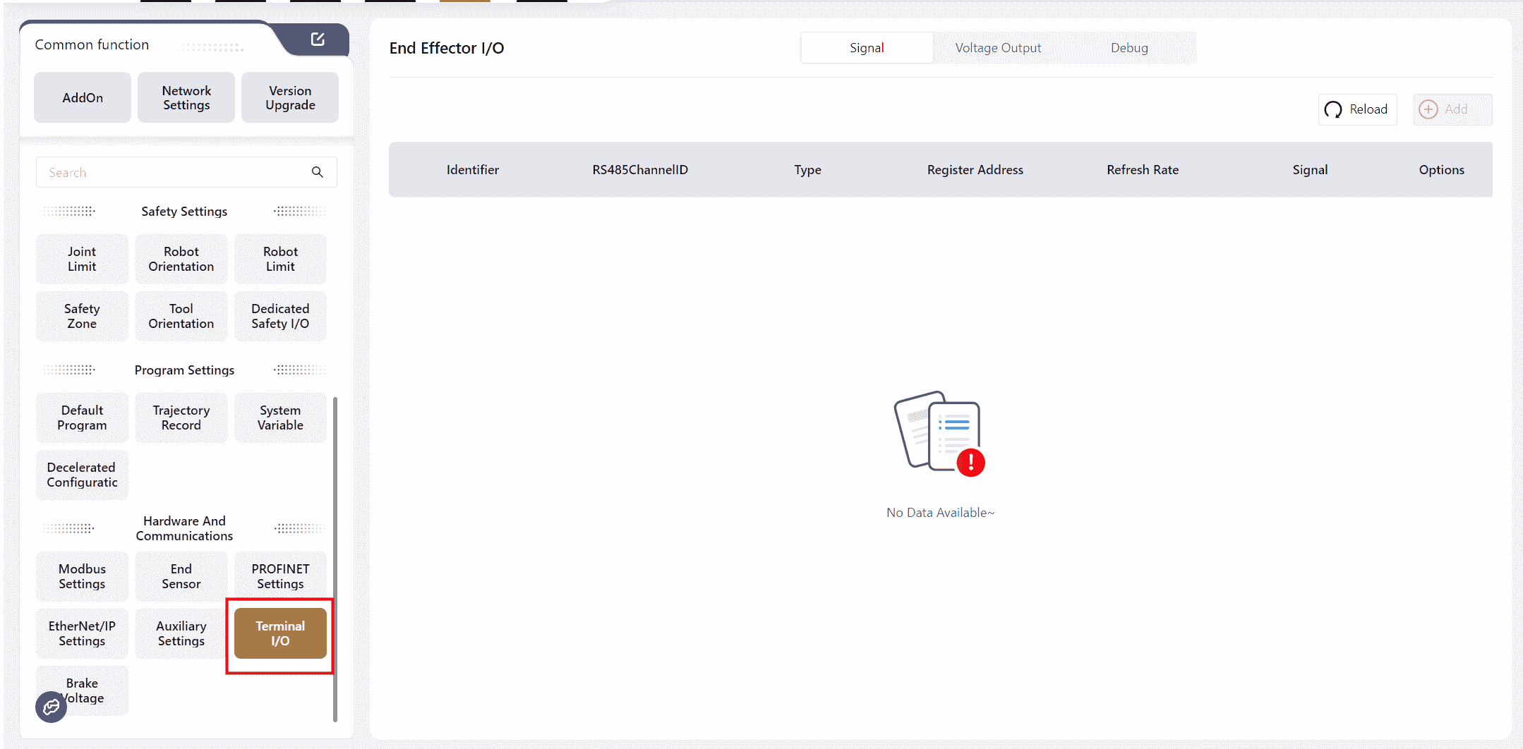
After connecting the end tool, it is necessary to configure it in the I/O Panel - Fixed I/O - Tool Side section while the robot is in the Powered On and Disabled state.
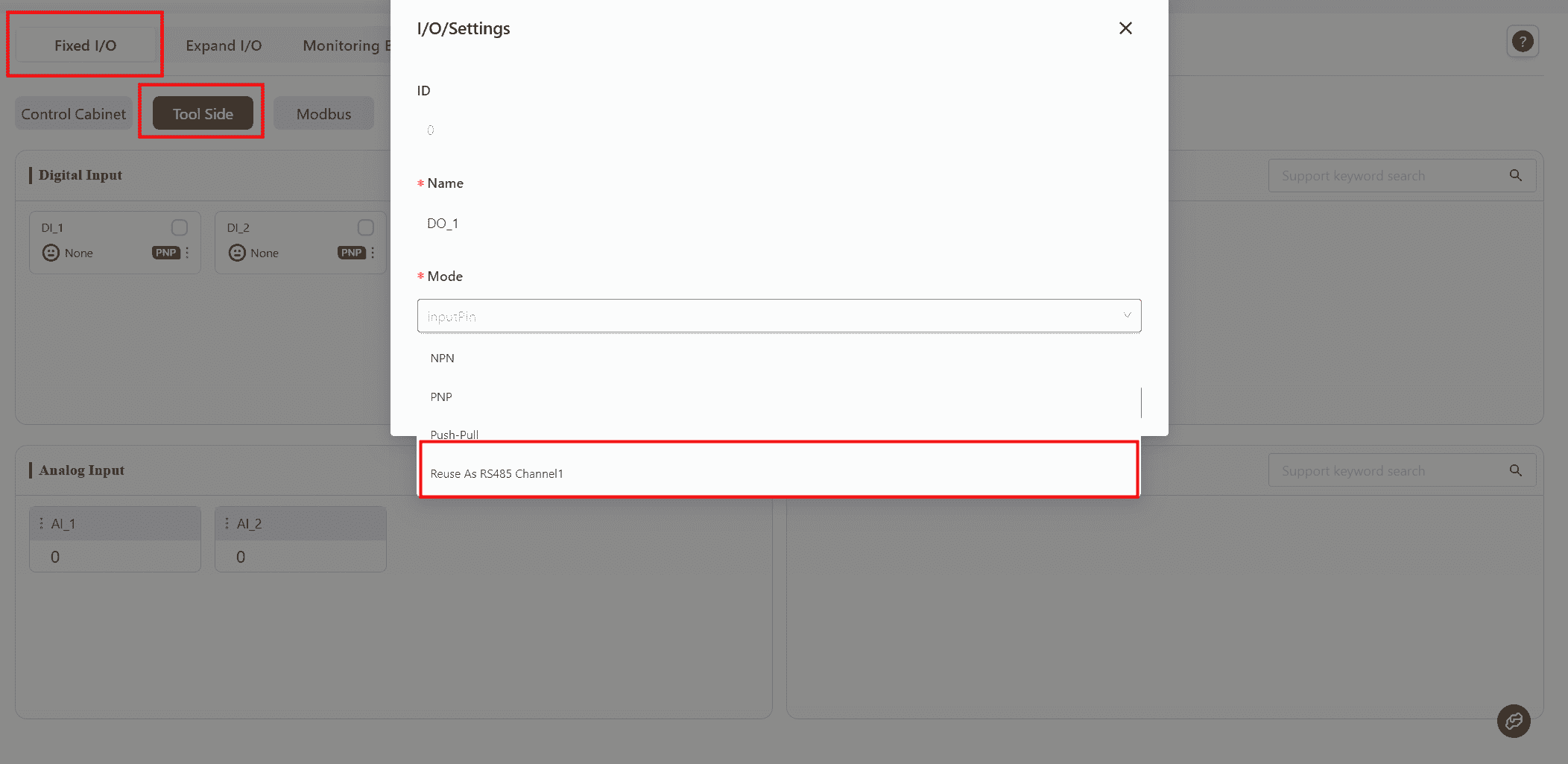
In Digital Output , select a DO and set its function to Repurpose as RS485 Channel 1 , then click Confirm.
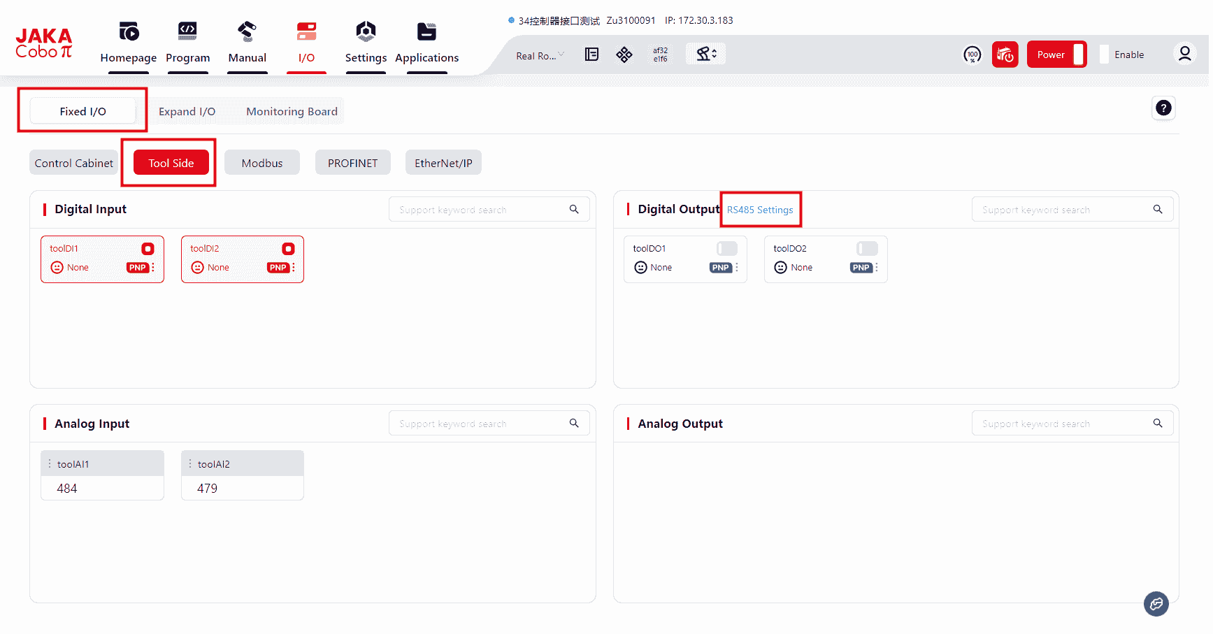
Once configured, the RS485 Configuration button will appear, allowing access to the RS485 channel configuration interface.
There are three modes available for RS485 configuration:
- Modbus RTU
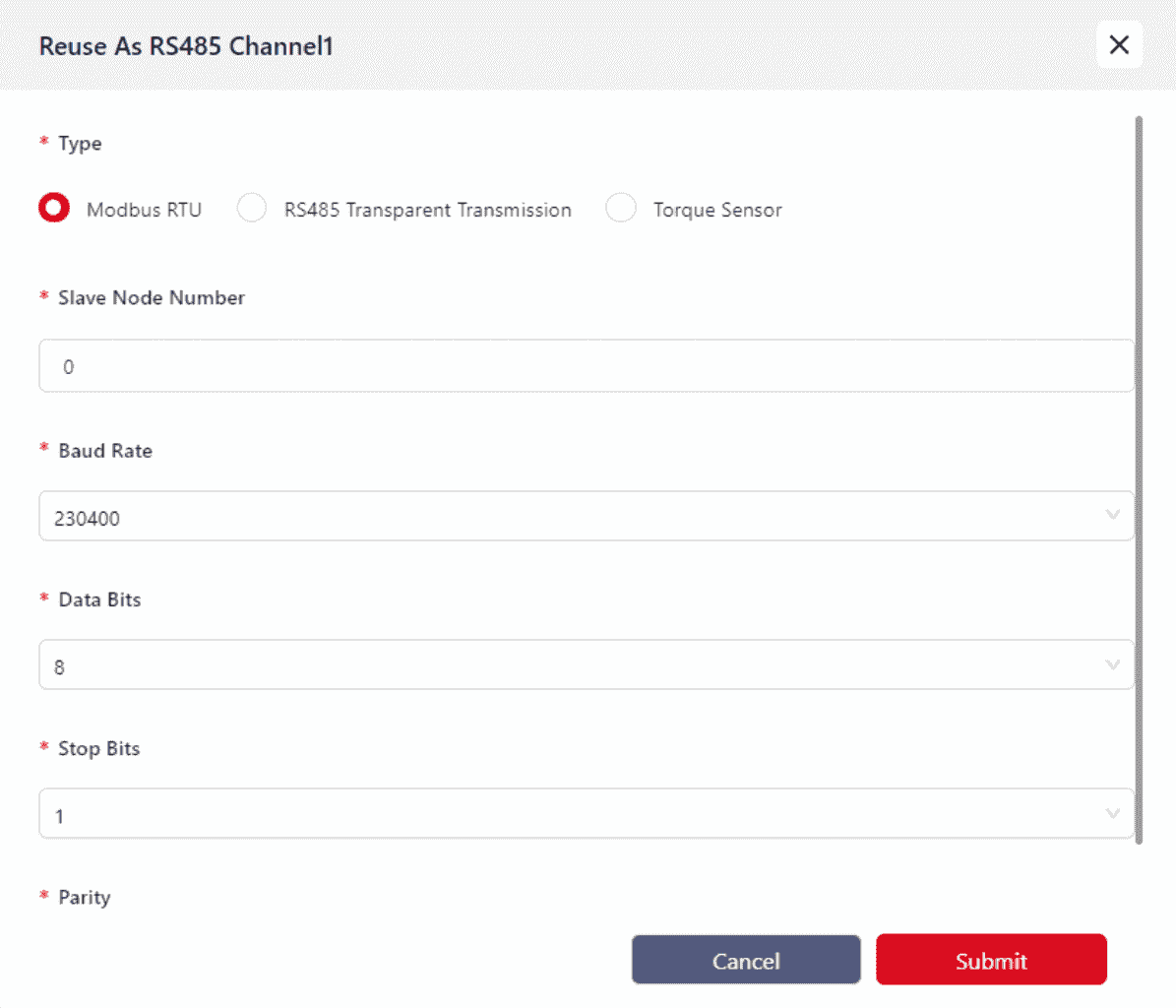
Mainly used for communication with external devices like grippers.
Currently, only grippers that support Modbus RTU communication are supported. Before connecting the gripper to the TIO terminal, ensure that the terminal connector definitions are understood to ensure correct wiring.
Refer to the hardware user manual of the respective model for wiring instructions.
- RS485 Transparent Transmission
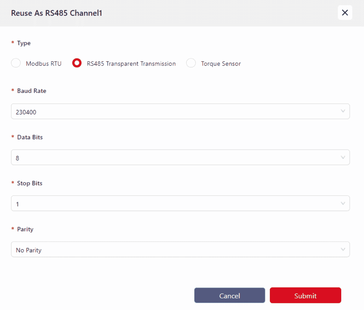
Currently, no devices are supported. This feature will be available in future upgrades.
- Torque Sensor Mode
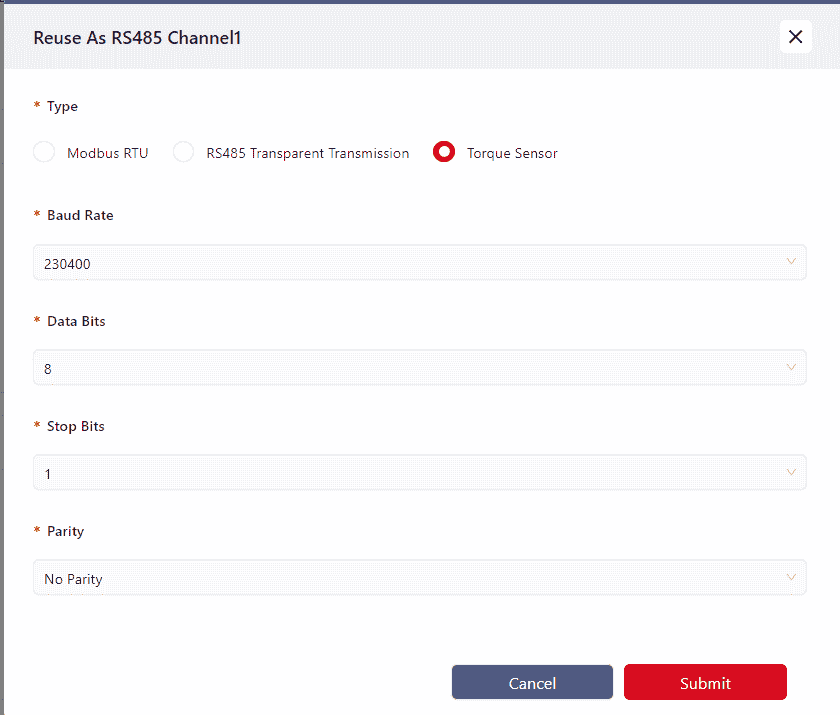
Mainly used for connecting VI model torque sensors.
Warning:
Currently, the torque sensor only supports RS485 Channel 1.
Parameter Configuration:
Baud Rate: Supports up to 230400
Data Bits: Supports 8, 9
Stop Bits: Supports 1, 2
Parity: Supports Odd, Even, None
Incorrect communication parameter configuration will prevent TIO from communicating properly with external devices.
Semaphore
When the TIO's DO or AI is configured for Modbus RTU mode, the semaphore status reading parameters for the Modbus device can be set here. The status of the corresponding semaphore can then be obtained by refreshing or querying.
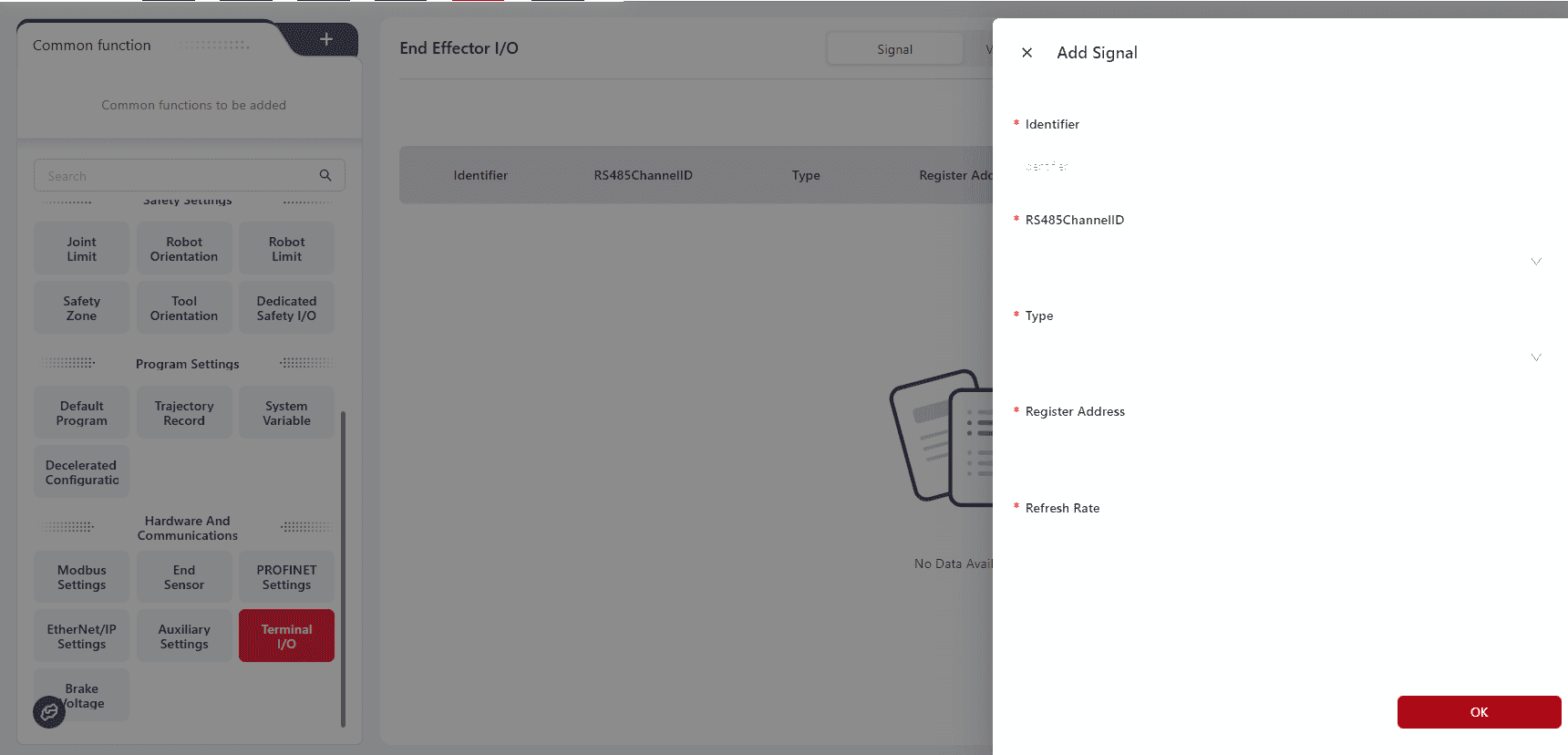
The meaning of semaphore is as follows:
- Semaphore Identifier: A unique identifier for the semaphore (Unicode and special characters are not supported), used for refreshing, retrieving, and deleting.
- RS485 Channel: Specifies the TIO RS485 channel, either RS485 Channel 1 or RS485 Channel 2, as the source of the semaphore.
- Semaphore Type: This parameter corresponds to the Modbus function code. 01 for coil register, 02 for discrete input, 03 for read holding register, 04 for read input register; other codes are currently not supported.
- Register Address: The Modbus register address corresponding to the semaphore, represented in decimal. This address, combined with the RS485 channel configuration and signal type, enables access to the specified register on the Modbus RTU slave.
- Refreshing and Querying Semaphore:
- Once the semaphore is defined, it can be debugged or monitored in the debugging interface or used directly in the operation program. Both methods provide interfaces for refreshing and querying semaphores. The refresh operation triggers data interaction between the controller and the TIO gripper. Since the interaction between the controller and external TIO devices is asynchronous with the refreshing command, it is recommended to wait a certain period (100ms) after refreshing to ensure the updated value is obtained.
- The refreshing rate can be set. When the frequency is 0, it only refreshes once; when the frequency is greater than 0, it will be refreshed as much as possible based on the communication bandwidth. If only one set of signals exists, the highest refreshing rate defaults to 20. If there are multiple sets of semaphores, reduce the refreshing rate for all to below 5.
Note:
The semaphore definition must be completed after the TIO I/O pin has been repurposed as an RS485 channel and set to Modbus RTU mode. Any changes to the mode or pin repurposing will result in the loss of the current semaphore configuration.
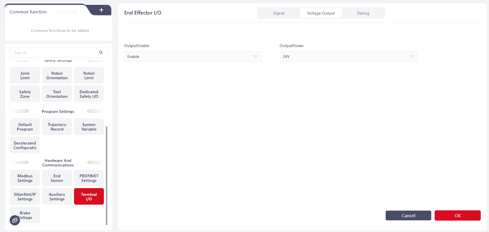
Voltage Output
The tool-end TIO has an end power output function, allowing the user to choose whether to output voltage and select the output voltage value as 12V or 24V.
Debugging
The debugging interface is used to send instant commands. These commands control the TIO external gripper in real-time, including position control, speed control, and force control.
Steps to send instant commands: Select the channel, type, enter the data command in hexadecimal or octal, and click "Confirm."
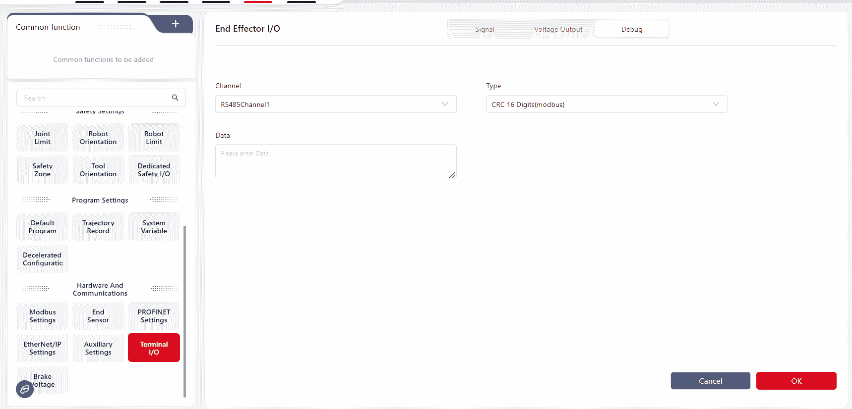
Note:
When entering instant command data in the data text box, only the command data needs to be written; the CRC check value will be automatically added by the control system.
Tip:
Communication commands in the programming interface support semaphore refreshing and querying.
The definition, modification, and deletion of semaphores must be manually added in the "Debugging" interface.
Additionally, instant command sending commands are provided for real-time control of external devices.
Click the "Help" button in the programming interface to view command descriptions, or visit https://www.jaka.com/docs/guide/cmdhelp.html for descriptions.
Brake Voltage
Warning:
This feature is only applicable to the MiniCab.
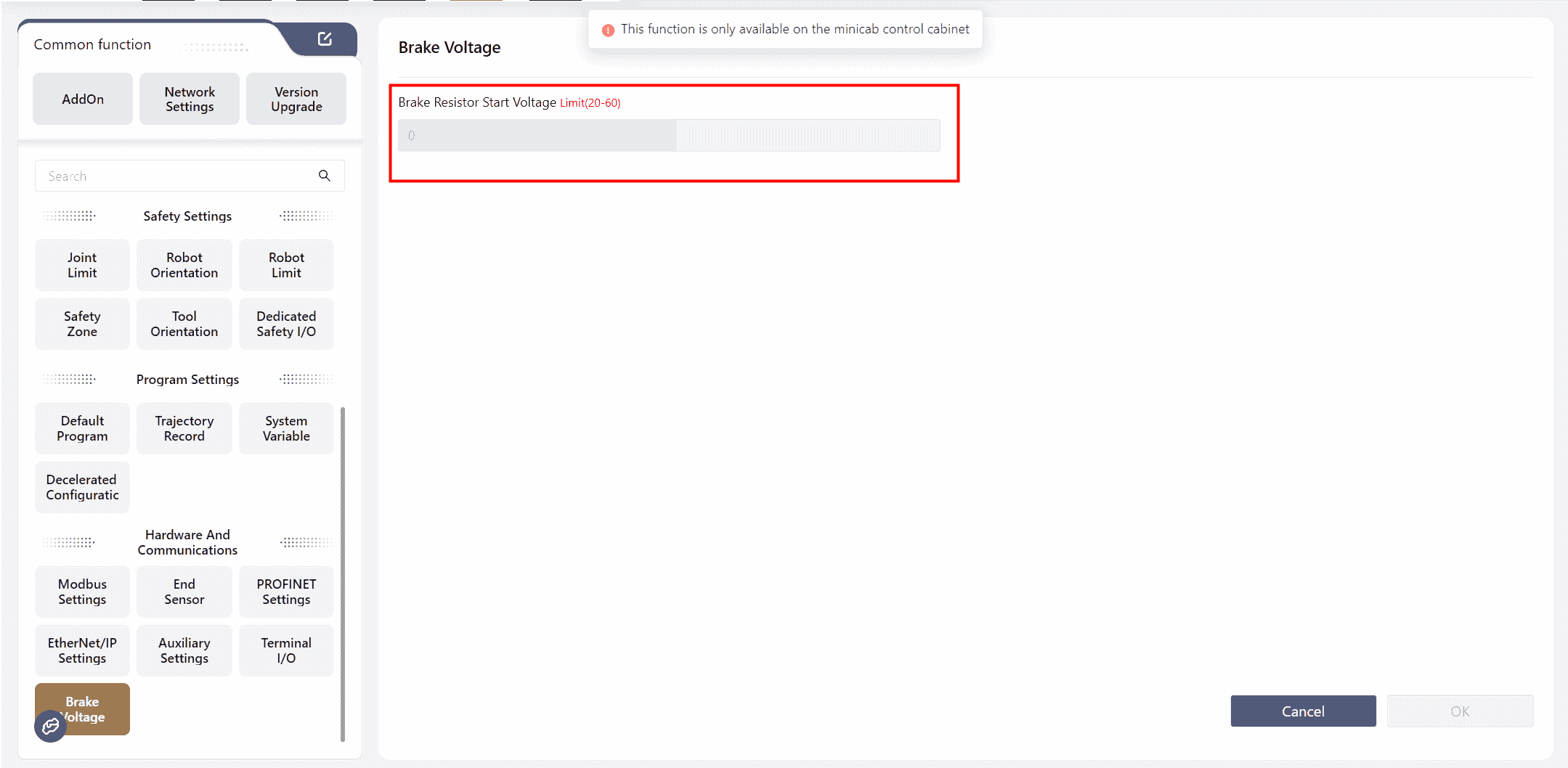
The MiniCab integrates a voltage braking circuit to dissipate the electromotive force generated during robot deceleration and braking. When using an external power supply, the braking voltage for the MiniCab must be set to avoid overvoltage protection shutdowns or damage to the controller.
The robot must be powered off to set the voltage.
The relationship between the brake voltage (V-Brake) and input voltage (V-IN) is V-Brake ≥ (V-IN + 3)V. The following table shows the recommended set values and corresponding power supply types based on common input voltage types:
| Power Supply Type | Voltage V-In[1] | Brake Resistor Activation Voltage V-Brake V-Brake[2] |
|---|---|---|
| 48V Module Power Supply | 48V | 51V |
| 48V Lithium Battery | 54.6V | 58V |
| 24V Module Power Supply[3] | 24V | 27V |
This voltage value is typical and must not exceed 60V. If the input voltage exceeds 56V, the overvoltage threshold for the robot must be modified. ↩︎
When V-Brake is set to less than (V-In + 1)V, internal logic will provide protection for powering on, and the page will prompt "Robot Voltage or Voltage Configuration Abnormal". ↩︎
The 24V module power supply is used for the MiniCobo and must not be used with Zu, C, or Pro series. ↩︎