Programming
Programming
Interface Overview
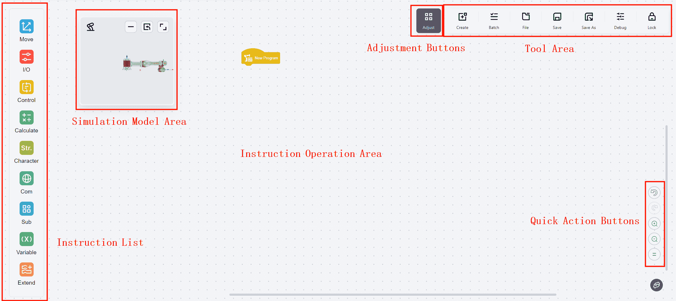
As illustrated, the programming interface is divided into several functional areas, each of which is described below in details.
Common Functions Overview
Commands List
Detailed descriptions of each command are provided below.
Simulation Model Area
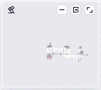
The simulation model area allows viewing the real-time operation of the robot.
By default, this window is floating in the upper left corner of the programming page. The window can be repositioned by dragging as needed.

Tips
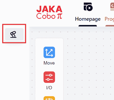
1 Robot button: Double-click to maximize the window.
2 Minimize button: Clicking this button will minimize the window and float it in the upper left corner of the page. After minimizing, click this icon again to restore the window to its normal size.
3 Restore Default State button: Clicking this button will restore the window to its default size and position.
4 Maximize button: Clicking this button will maximize the window.

- Additionally, the view can be zoomed in or out by hovering the mouse cursor over any position within the window and scrolling.
Commands Operation Area
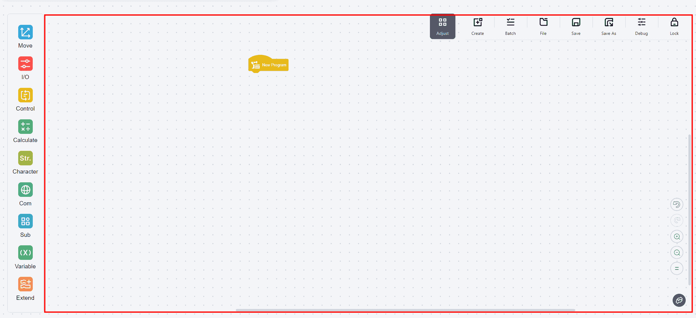
The Commands Operation Area includes all regions except other functional buttons. Commands can be assembled in this area.
- Clicking a single command will open a popup window for further operations.
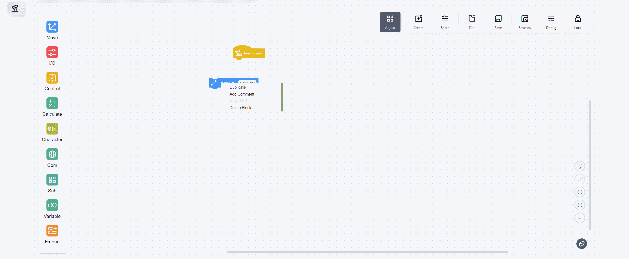
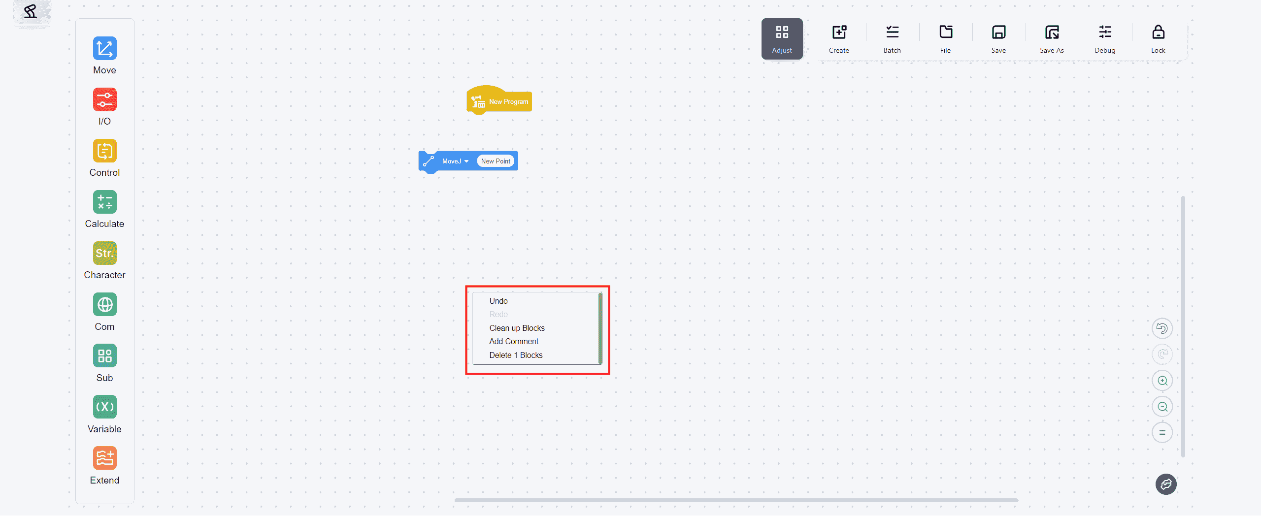
- Clicking a blank area of the canvas will open a popup window for further operations.
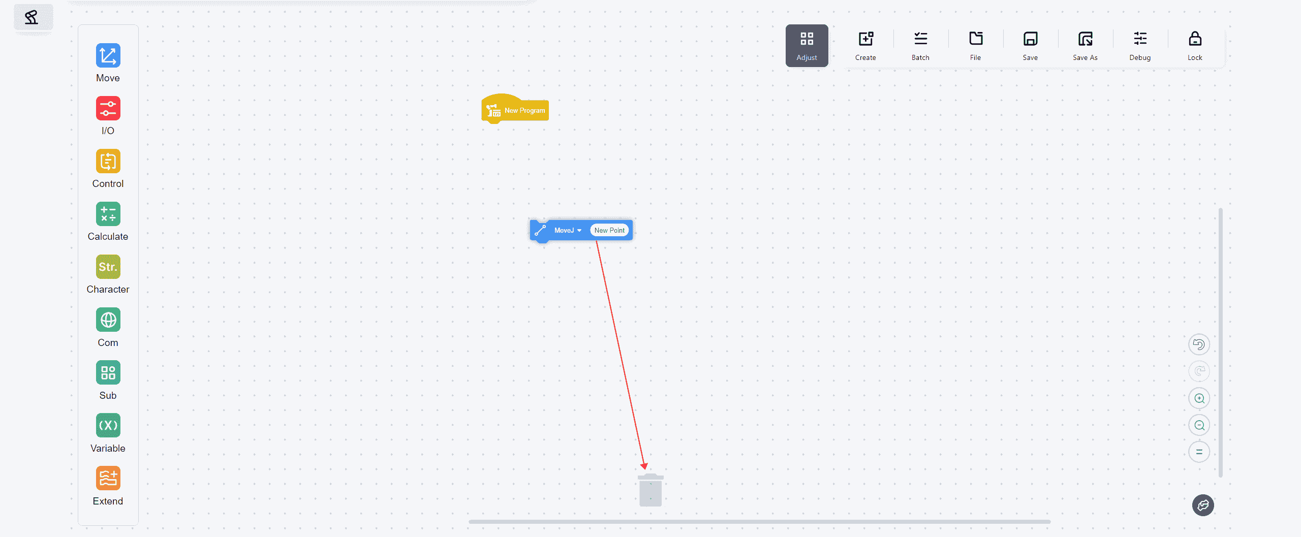
- Dragging any command will reveal a trash bin icon at the bottom of the operation area. Dragging commands to the icon to delete it.

Version 172 adds a new "Add Comment" feature, while all other functionalities remain the same as in version 171. Therefore, only the "Add Comment" feature will be explained in detail here.
- Click on the blank canvas to add comments:

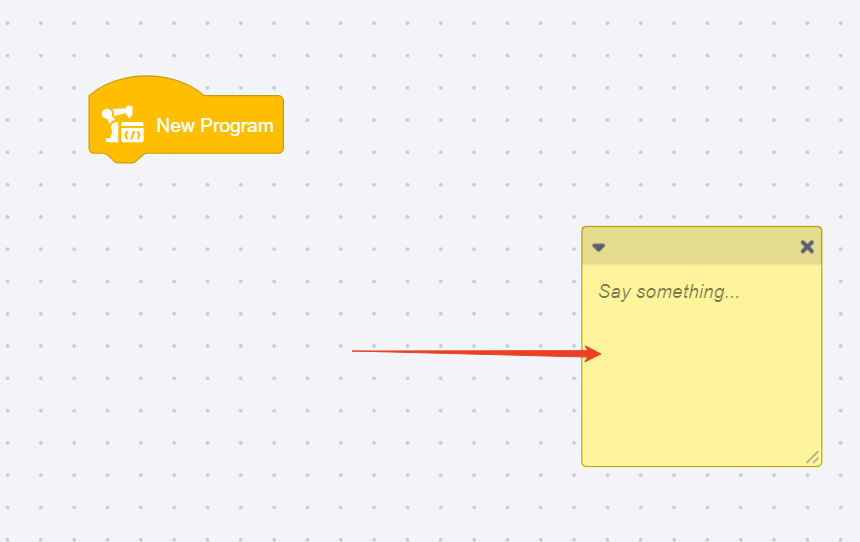
You can drag the comment box to any location on the canvas using the mouse.
- Click on a specific command to add a comment:
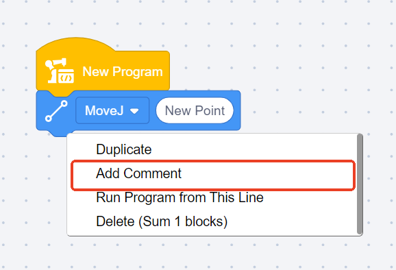
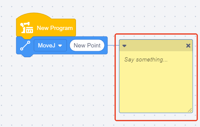
The comment box can be dragged to any location on the canvas using the mouse.
- Commands that are edited would appear a pencil icon in the front:

Adjust Buttons
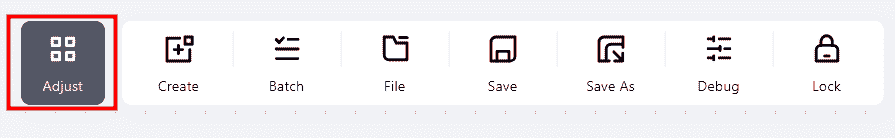
Clicking this button will open a popup window for further operations.
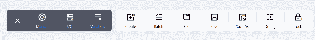
Manual
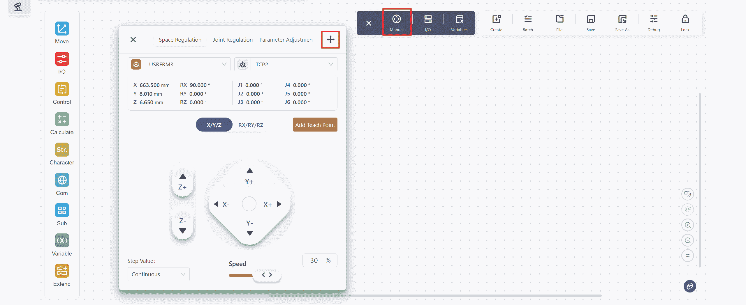
Operations are the same as those in the Manual of the top navigation bar.
The button in the upper right corner allows free movement of this window to any position on the page.
I/O
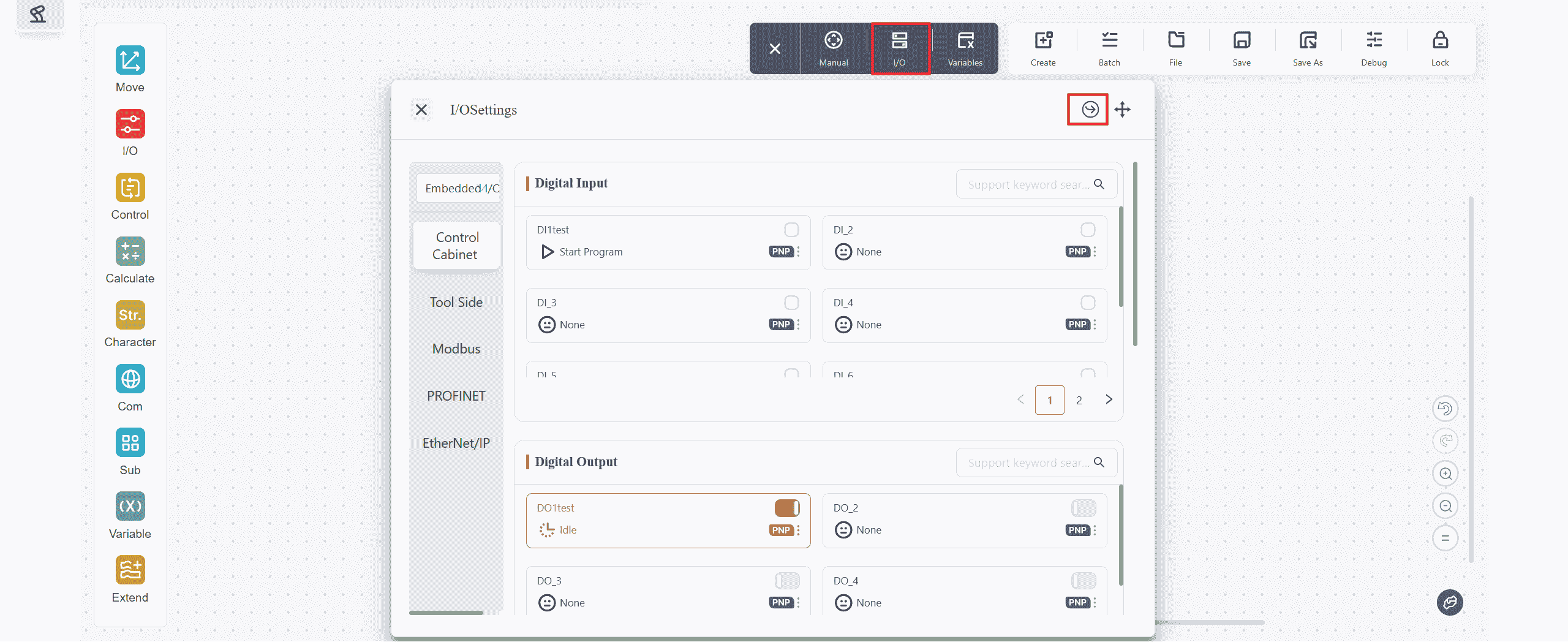
Operations are the same as those in the I/O Panel of the top navigation bar. Reference:
Clicking the button in the upper right corner allows jumping to the Settings - Modbus Settings page.
Variables

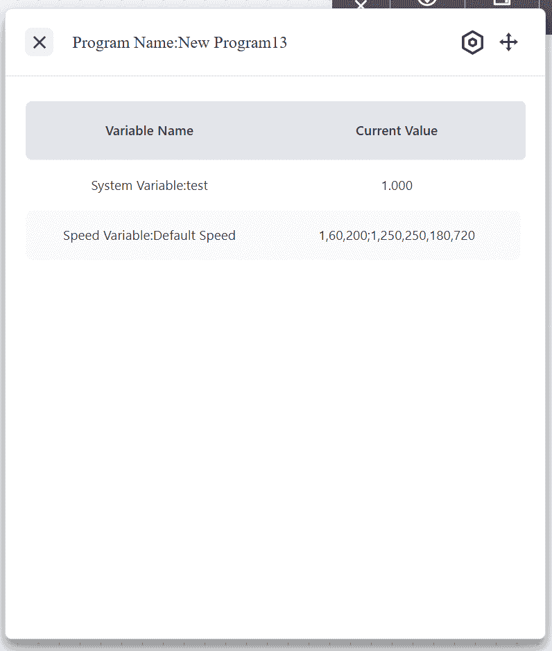
Clicking Variables will open the default blank page as shown above. Clicking the button in the upper right corner opens the Set Observation Variables, where variables to be observed in this window can be added.
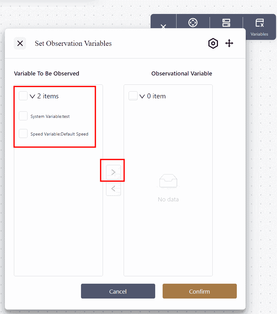
Check the variables to be observed, multiple selections are possible;
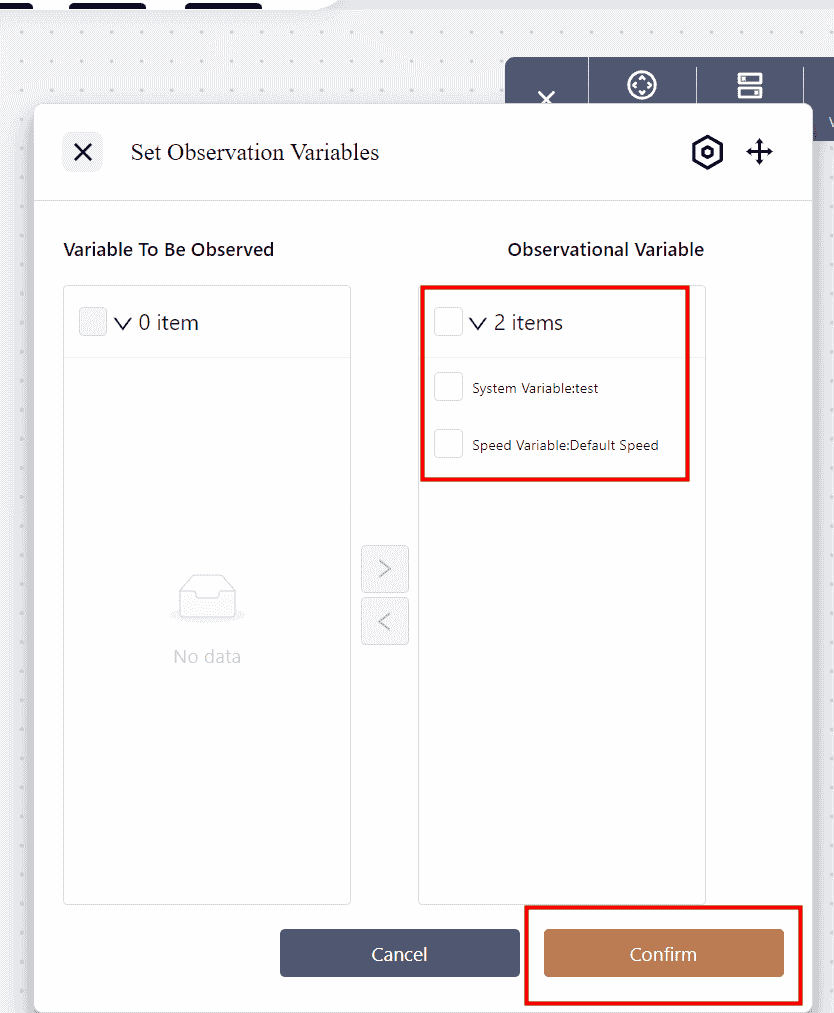
Click to move the selected variables to the box on the right;
Click to confirm and apply the changes.
Tool Area
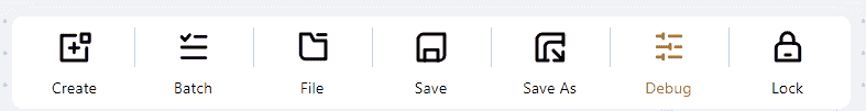
Create
Click to create a new program.
Batch
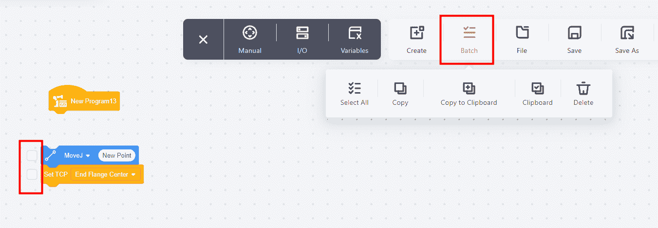
After clicking Batch, a dropdown menu will appear, allowing batch operations on the program.
Multiple commands can be selected from the checkbox on the left, and corresponding functions can be chosen from the dropdown menu.
Note:
After selecting the commands for operation, clicking Copy to Clipboard will copy these commands to the Clipboard.
After opening another program or creating a new one, the previously copied commands can be found by opening the Clipboard from the same location.
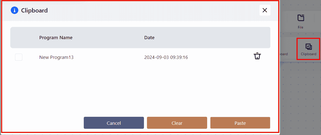
Select the desired commands and click Paste to insert the commands into the new program.
File
Click File to directly select a programming file from the list for further operations.
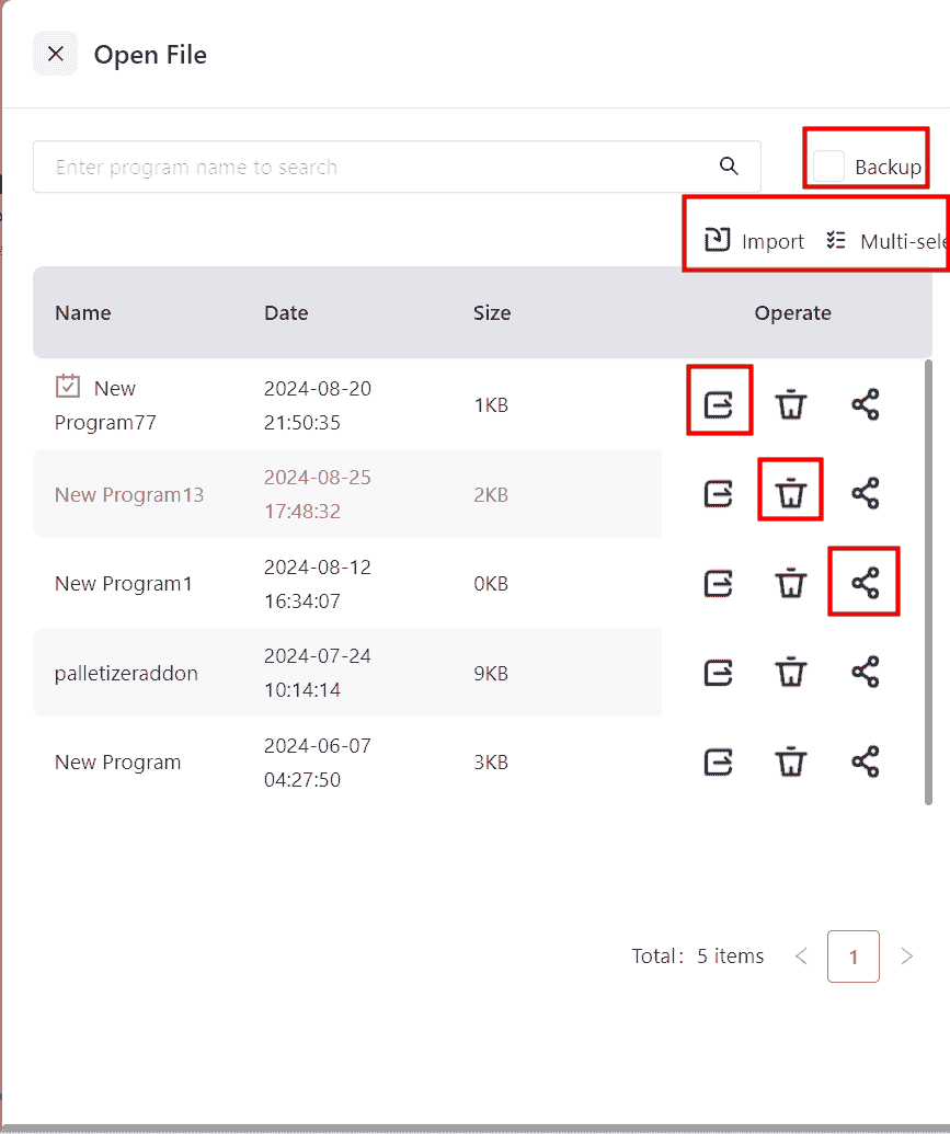
In version 172, the Import feature supports importing multiple files simultaneously, with a maximum of five files per import.
Save
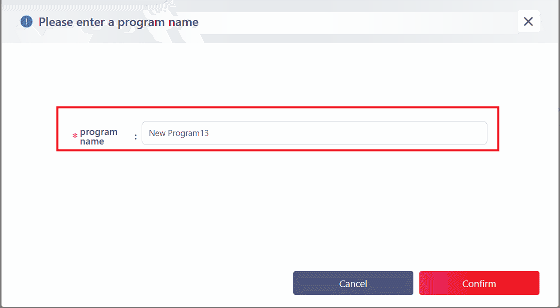
Save As
Click Save As to perform the corresponding operation.
Debug
Click Debug to put the robot into debugging mode, where it will pause after executing each command. Manual intervention by clicking Next Step is required to proceed to the next command.

Lock
After clicking Lock , the currently opened program will be locked and no further operations can be performed. Clicking Unlock will exit this state.
Quick Action Buttons

1 :Undo action
2 :Redo action
3 :Enlarge command block
4 :Reduce command block
5 :Reset
Commands List
Movement (Motion Commands)
Note:
Note:
The robot's movement position will change according to the coordinate system.
If points in a program are set under one coordinate system and the coordinate system is then changed, all previously set points will automatically shift to the corresponding positions in the new coordinate system.
Therefore, to ensure precise execution of movement commands, it is important to confirm the current coordinate system before editing or executing movement commands.
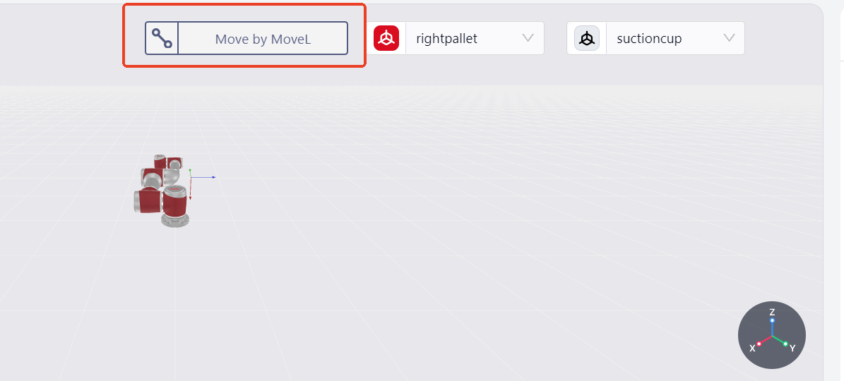
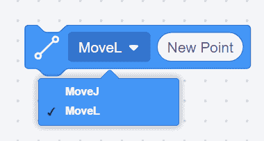
Version 172 introduces new icons on the robot motion-related command editing page:
The motion method displayed by this icon is the same as the one selected in the Edit page.
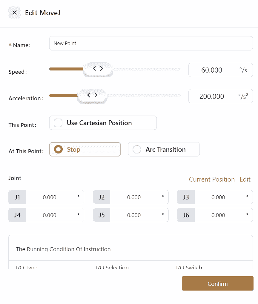
Joint Movement

- Enables the robot to perform joint movements.
- Click the icon to open the settings interface, where
NameSpeedAccelerationcan be edited, and options forUse Cartesian PositionStop or Arc TransitionandThe Running Condition of Commandcan be selected. InJoint Angles-Edit, the manual operation page can be opened to edit teaching points; the robot can also be dragged to the desired position, and by clickingJoint Angles-Current Position, the specific angles of the robot's joints will be displayed on the interface.

Note:
When using joint movement, if Use Cartesian Position is selected, the robot will calculate the corresponding joint angles from the Cartesian position saved in the current movement and then perform the joint movement to the set position.
Joint Movement Using Cartesian Coordinate

- Enables joint movement using points recorded in Cartesian coordinates.
- If this command is placed before a joint movement command, subsequent joint movements will use the points recorded in the Cartesian coordinate system, and the robot will automatically perform inverse kinematics.
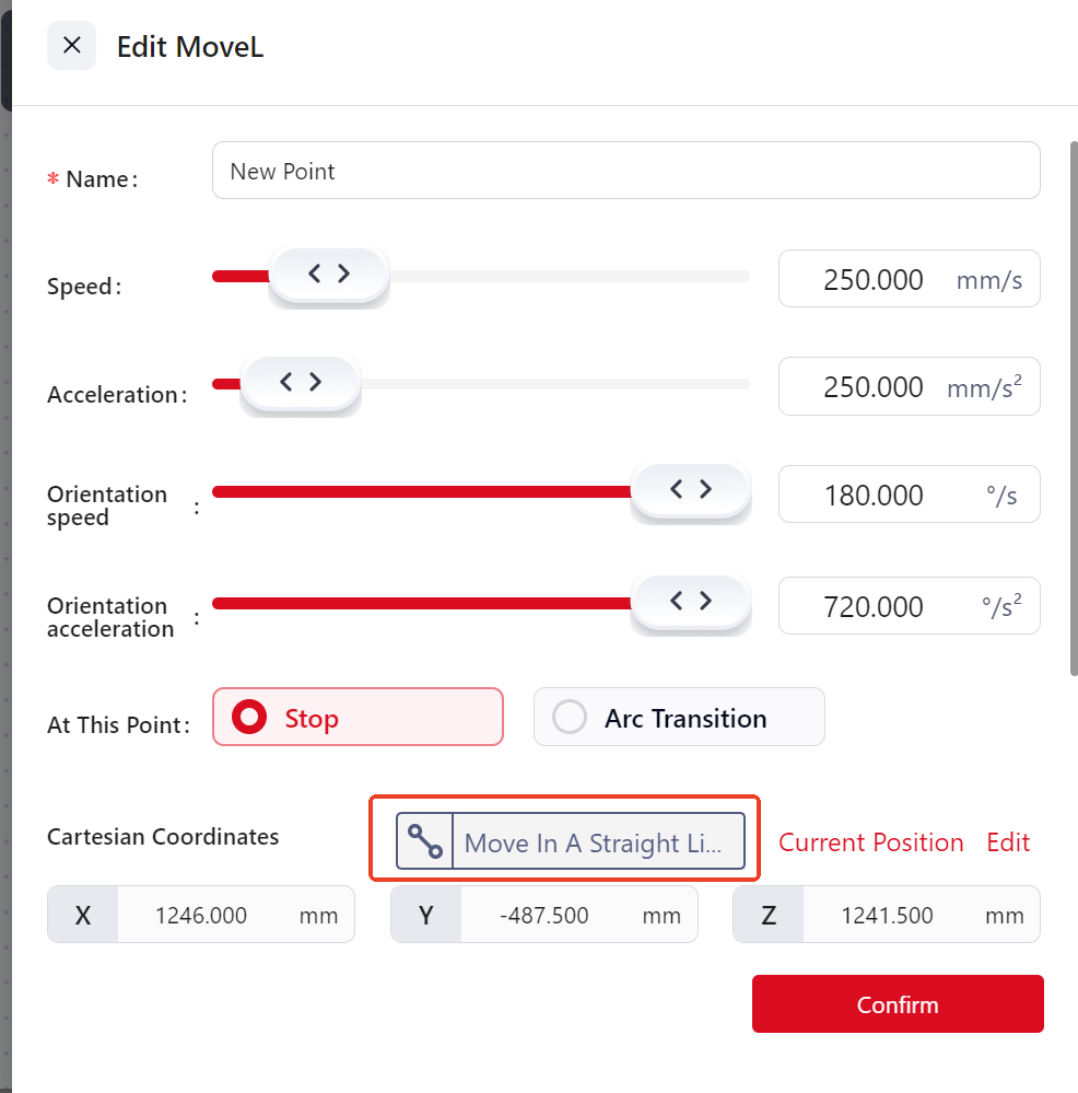
Linear Movement
- Enables the robot to perform linear movements.
- Click the icon to open the settings interface, where
NameSpeedAccelerationOrientation speedOrientation accelerationcan be edited, and options forUse Cartesian PositionStop or Arc TransitionandThe Running Condition of Commandcan be selected. InCartesian Coordinates-Edit, the manual operation page can be opened to edit teaching points; the robot can also be dragged to the desired position, and by clickingCartesian Coordinates-Current Position, the specific values of the robot's coordinates will be displayed on the interface.

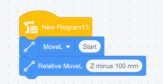
Relative Linear Movement

- Sets the position change amount to perform end-effector linear movement relative to the current pose, with the position change amount being the incremental value in the current user coordinate system.
- Click the icon to open the settings interface, where
NameReference Coordinate SystemSpeedAccelerationOrientation speedOrientation accelerationcan be edited, and options forStop or Arc TransitionandThe Running Condition of Commandcan be selected. The position change amount can also be edited.
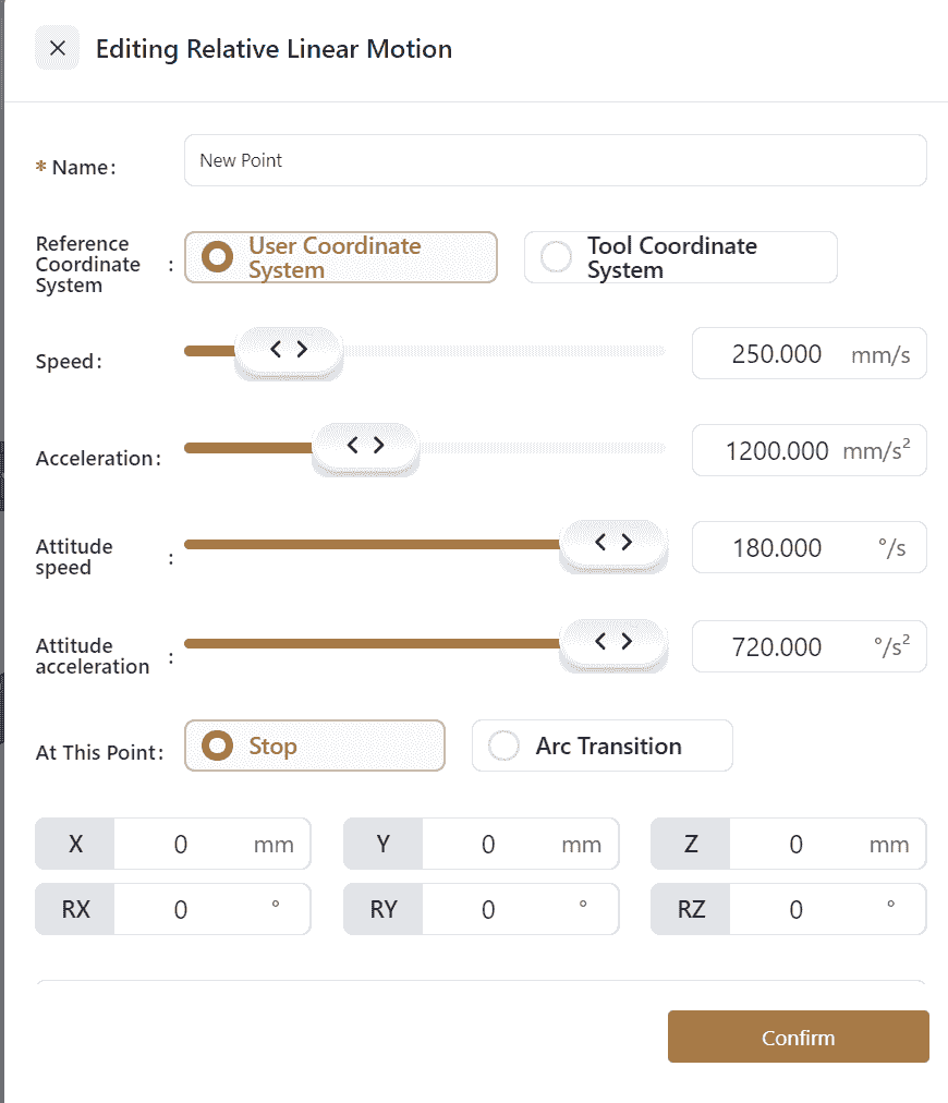
- Example: The robot's end-effector moves 100mm along the negative Z-axis of the current user coordinate system.
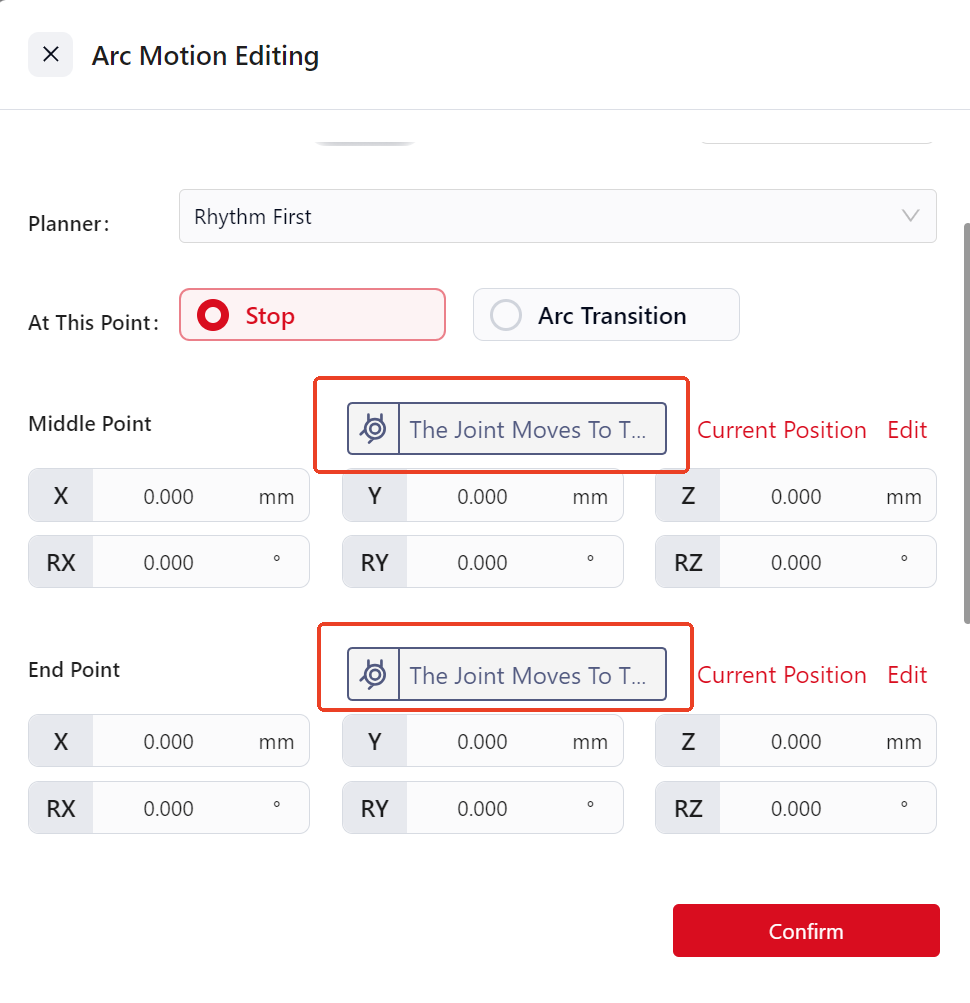
Arc Movement
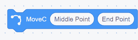
- Arc movement requires three points: P0, P1, and P2.
However, as shown in the above image, only two points (P1 and P2) can be set in the command, so P0 needs to be set separately. If there is another command before the arc movement, P0 will be the last point of the previous command; if there is no other command, a motion command needs to be added before the arc movement, making the last point of that command the P0 for the arc movement.
P1 is the first point of the arc movement command, labeled Arc Point 1, and P2 is the second point, labeled Arc Point 2.
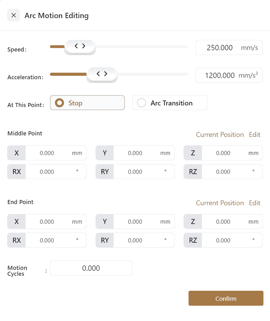
- Click the icon to open the settings interface, where
SpeedAccelerationcan be edited, and options forStop or Arc TransitionThe Running Condition of Command, manual teaching or direct editing ofCartesian Coordinates for Point 1Cartesian Coordinates for Point 2, andNumber of Motion Circlescan be selected.
Number of Motion Circles:
The number of motion circles must be an integer.
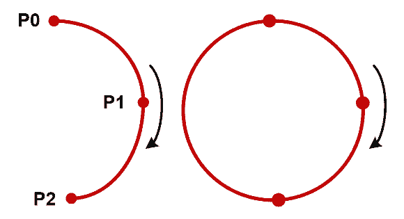
When the number of circles is 0, the arc motion trajectory is the arc from the initial point to the end point;
When the number of circles is 1, the system automatically calculates a full circle using the set initial point, passing point, and end point. The arc motion trajectory will be one full circle as calculated by the system;
When the number of circles is 2, the arc motion trajectory will be two full circles, and so on.
MoveZ
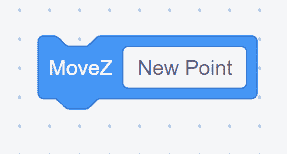
- The robot's end-effector moves in a zigzag pattern while maintaining the current pose.
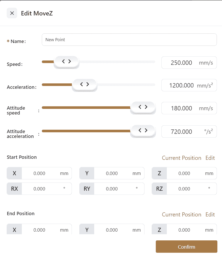
- Click the icon to open the settings interface, where
Namecan be edited, manual teaching or editing ofStart PositionEnd PositionArbitrary Position, and editing ofZigzag WidthMovement Speedcan be done.Zigzag Densitycan be selected, and one ofArc TransitionorPause Time at Peakscan be chosen.
Note:
Zigzag Width:The width of the robot's movement in the current plane.
Zigzag Density:The distance between peaks on the same side, determining the robot's movement cycle. If the zigzag density is not set, the zigzag movement cycle is determined by the current robot speed.
Pause Time at Peaks:The robot will pause at each peak. Different pause times can be set at +X Side Point and -X Side Point.
By default, the plane perpendicular to the user's coordinate system's Z-axis is the plane of the robot's movement. The movement plane can also be customized by adding a new point(Arbitrary Position), which will cause the plane formed by Start Position End Position and Arbitrary Position to become the robot's zigzag movement plane, with Arbitrary Position indicating the +X direction.

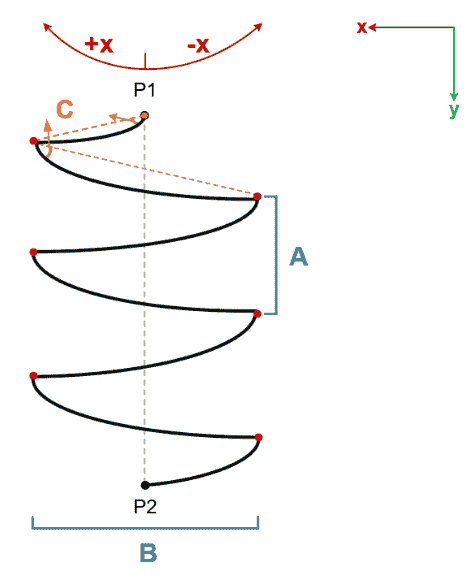
MoveZS

- The robot's end effector rotates along the RZ axis while simultaneously moving in the specified direction.
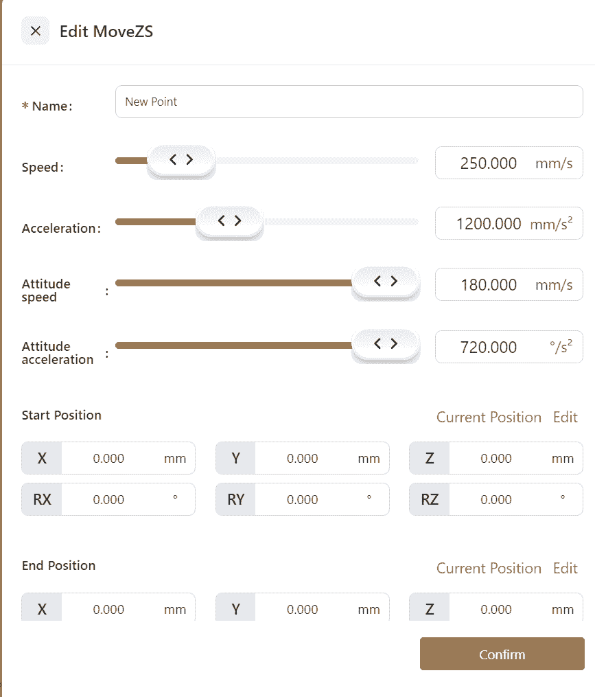
- Click the icon to open the settings interface. Edit the
Namefield, manually teach or edit theStart PositionEnd PositionArbitrary Position. Adjust theZ-Shaped WidthMovement Speed,Optional settings includeZ-Shaped DensityRotation Angle. Choose betweenArc TransitionandPeak Pause Time
Note:
Z-Shaped Width:The width of the robot's movement on the current plane.
Z-Shaped Density: The distance between peak points on the same side, determining the robot's movement cycle. If not set, the current movement speed will dictate the Z-shaped movement cycle.
Rotation Angle:The angle of rotational movement along the positive or negative X-axis.
Peak Pause Time: The robot will pause at each peak. Different pause times can be set for the +X Side Point -X Side Point.
By default, the robot moves in a plane perpendicular to the Z-axis of the user coordinate system. The movement plane can be customized by adding an(Arbitrary Position. The plane formed by the Start Position End Position Arbitrary Position will then serve as the Z-shaped movement plane, with the direction of the Arbitrary Position being the +X direction.
Pallet Waypoint

- This command sets the end point of the robot's movement for each tray point in a tray program.
- Click the icon to open the settings interface. Edit the
NameSpeedAccelerationof the command. Choose whether toStop or Use Arc Transition. Set theCommand Skip Conditionand manually teach or edit the waypoint inCartesian Coordinates.
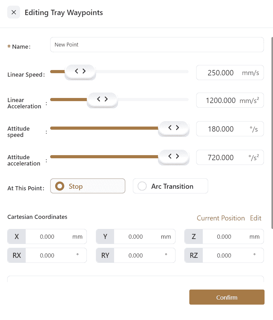
- Example: The robot end effector follows a 3x3 square tray and moves 100mm downward at each point.

Trajectory Record
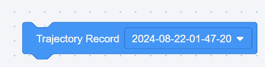
- This command reproduces trajectories that have been recorded in
Settings-Program Settings-Trajectory Record.
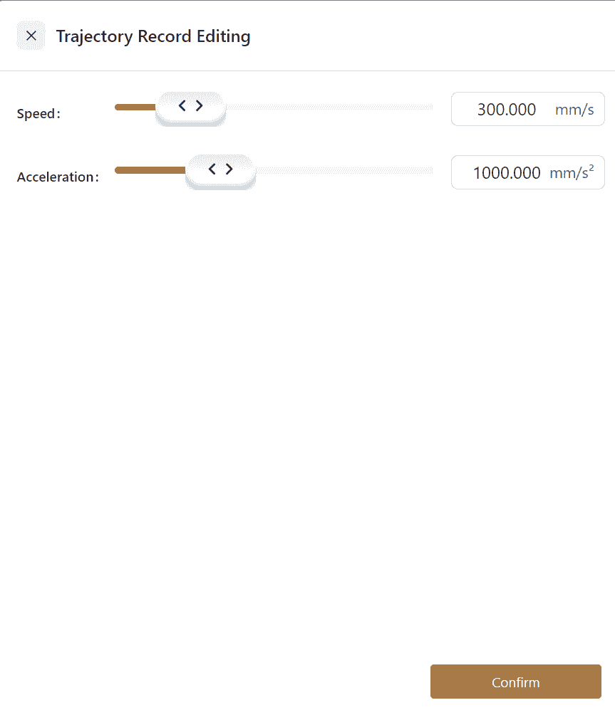
- Open the settings interface to adjust
Speed-Acceleration.
Set Global Speed

- This command sets the motion speed and acceleration for all subsequent linear and joint movements to match the selected speed variable.
Close Global Speed

- This command restores the original speed and acceleration for all subsequent linear and joint movements.
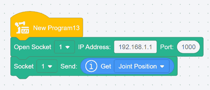
Get Robot Parameters

- Robot parameters can be sent to the host computer or assigned to a variable.
- Example: The host computer receives the current angles of the robot's joints 1 through 6.
Get Robot User or Tool Coordinate System

- The robot's coordinate system values can be sent to the host computer or assigned to a variable.
- Example: The host computer receives the current robot coordinate values.
Check Cartesian Space Reachability

- This command checks whether the robot can reach the specified point through Cartesian space movement.
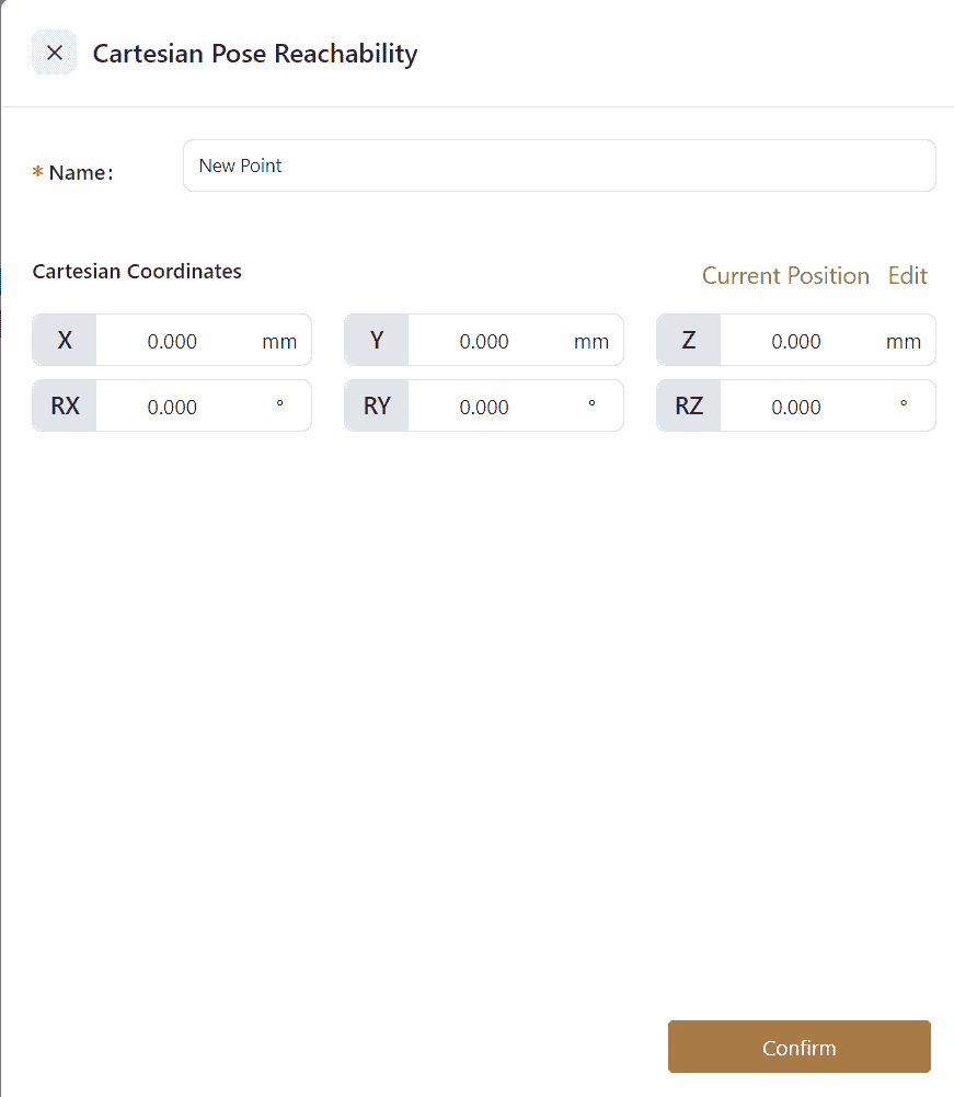
- Click the icon to open the settings interface, where the point name can be edited, and the point can be manually taught or directly edited.
Check Cartesian Space Reachability (with angle value)

This command can accept a position variable representing a joint angle, and based on this angle, it will calculate corresponding reachable points.
Pose queue Save/Get

This command is used to save or retrieve material positions obtained from camera captures.
Clear Pose queue

This command is used to clear the stored material position information obtained from camera captures.
Planner Setting
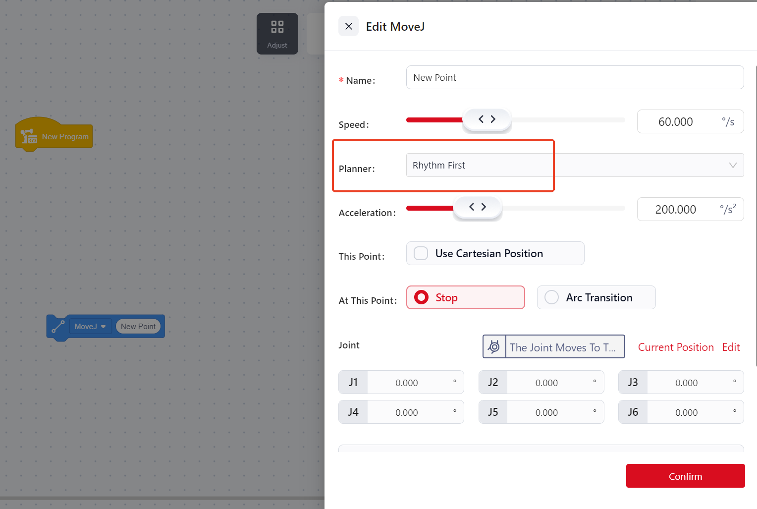
During the robot program execution, the planner type can be set to either:Cycle Priority/ Smooth Priority
- Cycle Priority:In this mode, the robot's velocity changes linearly during acceleration and deceleration. Choosing cycle priority allows for faster robot operation, but the initial and final phases of acceleration may impose greater impact on the robot. This mode is generally used in high-cycle scenarios and is the default planning method.
- Smooth Priority:In this mode, the robot's acceleration follows an S-curve, ensuring a constant rate of change of acceleration. This results in smoother motion with reduced impact on the robot, making it suitable for scenarios where high trajectory precision is required but cycle time is not critical. Smooth priority is effective when controlling the robot programmatically or moving joints to a specific point but does not apply in manual operation, drag mode, or when moving linearly to a point.
Apart from configuring the planner type for individual motion instructions in the editing interface, the following two global commands are introduced for overall configuration:
Set Global planner type

Disable Global planner

Note: When global planning is enabled, all motion commands between these two global commands will follow the global planning configuration, which takes precedence over the planner type set for individual instructions.
I/O
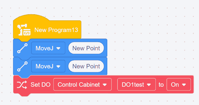
Set Digital Output

This is an immediate command. When used in a program, it instantly outputs the specified digital output (DO) signal.
Example: Release the soft gripper to place the object after moving to the object placement point.
Set Digital Output During Movement
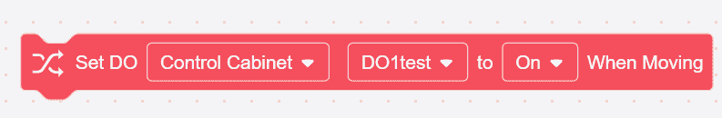
- This is a non-immediate command. When used in a program, the DO signal is not immediately output but waits until the robot starts moving to output the signal.
- The two commands adjacent to this command must both be movement commands, and arc transition must be enabled.
Wait for Digital Input

- This command is used to wait for a digital input (DI) signal.
- If the input time is set to 0, the program will wait indefinitely at this command until the condition is met before executing the next command.
If the waiting time is not 0, the program will execute the next command immediately if the condition is met, or it will wait for the specified time before executing the next command if the condition is not met.
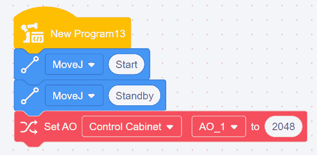
Set Analog Output

- This is an immediate command. When used in a program, it instantly outputs the specified analog output (AO) signal.
- The value of the analog output signal can be entered in the white box of the command, with a range of -65535 to 65535.
- Example: Set the AO1 value of the control cabinet to 2048 after the robot moves to the standby point.
Set Analog Output During Movement

- This is a non-immediate command. When used in a program, the AO signal is not immediately output but waits until the robot starts moving to output the signal.
- The value of the analog output signal can be entered in the white box of the command, with a range of -65535 to 65535.
- The two commands adjacent to this command must both be movement commands, and arc transition must be enabled.
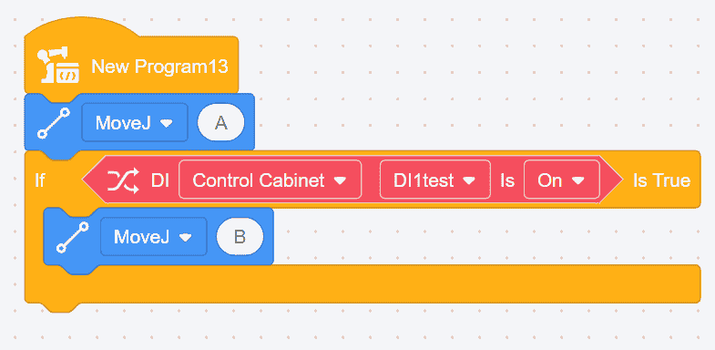
Digital Input

- This command is used to obtain the status of a digital input (DI) and must be used in conjunction with other commands. It can be used as a conditional check in the program. The condition is true when the DI status matches the one set in the command.
- Example: Check the current digital input status. If DI1 is on, the robot moves from point A to point B.
Digital Output

- This command is used to obtain the status of a digital output (DO) and must be used in conjunction with other commands. It can be used as a conditional check in the program. The condition is true when the DO status matches the one set in the command.
- Example: Check the current digital output status. If DO1 is on, the robot moves from point A to point B.

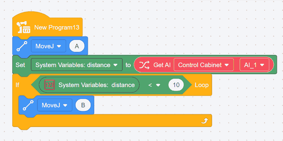
Get Analog Input

- This command is used to obtain the status of an analog input (AI) and must be used in conjunction with other commands. The analog input value can be assigned to a variable.
- Example: Assign the current analog input value to a system variable named "distance." If the "distance" variable is less than 10, the robot moves from point A to point B.
Get Analog Output

- This command is used to obtain the status of an analog output (AO) and must be used in conjunction with other commands. The analog output value can be assigned to a variable.
- Example: Assign the current analog output value to a system variable named "distance". If the "distance" variable is less than 10, the robot moves from point A to point B.

Control
Set Tool Coordinate System
When the coordinate system changes during program execution, use the Set Tool Coordinate System command. After using this command, all subsequent linear movements will operate within the coordinate system specified by this command, with no impact on joint movements.
There are two ways to set the tool coordinate system:
- Manually enter TCP


Click the icon to open the settings interface, where the coordinate system's name and values can be edited.
The coordinate system set here can only be used within this program.
- Select a Predefined TCP in
Settings.

Set User Coordinate System
When the coordinate system changes during program execution, use the Set User Coordinate System command. After using this command, all subsequent linear movements will operate within the coordinate system specified by this command, with no impact on joint movements.
There are two ways to set the user coordinate system:
- Manually Input User Coordinate System


Click the icon to open the settings interface, where the coordinate system's name and values can be edited.
The coordinate system set here can only be used within this program.
- Select a Predefined User Coordinate System in
Settings.

Set Payload and Center of Mass
When the load changes during operation, use the Set Payload and Center of Mass command. If the load set during operation does not match the actual load, it may cause vibration or false collision alarms.
This command modifies the end effector's load and center of mass during program execution. There are two ways to set this:
- Click the numeric keypad or manually input the actual load and center of mass.

- Place a Digital Variable block in the white box, and set the load and center of mass values in the variable's
Initial Valuefield.


Wait Command
There are two types of wait commands:

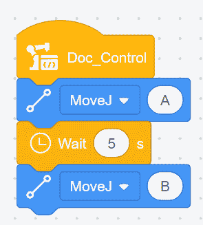
- Wait for a Specific Time
Enter the wait time, and the program will pause for the specified duration before continuing. If the wait time is set to 0 seconds, the robot will wait indefinitely.
Example: Pause for 5 seconds after the robot reaches point A, then continue.

- Wait for a Specific Condition
Enter the condition in the box, and the robot will wait until the condition is met before continuing.
Example: Wait until DI is on, then move the robot from point A to point B.

Loop Command
There are five types of loop commands:

- Loop for a Specific Number of Times: When the program reaches this command, it repeatedly executes the commands within the loop until the specified number of iterations is completed or until it encounters the "End Loop" command. There are two ways to set this up:
- Click directly on the number pad or manually input the number of iterations.
- Place a numeric variable block in the white box and set the loop count in the variable's
initial value.

- Loop Indefinitely: When the program reaches this command, it continuously executes the commands within the loop until the
End Loopcommand is encountered.

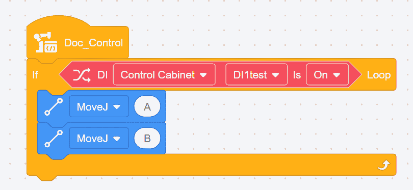
- Conditional Loop: Insert a condition command into the diamond-shaped box of this loop command. The loop will continue to execute the commands as long as the condition is met. The loop terminates when the condition is no longer satisfied or when the
End Loopcommand is reached.
Example: If the condition is met, the robot will repeatedly move between points A and B.

- End Loop:This command is used in conjunction with loop and condition commands. It terminates the nearest loop when a specific condition is met. By adding a condition before this command, the loop will terminate immediately when the condition is satisfied.
Example: If the condition for ending the loop is not met, joint movements ABCD are executed. If the condition is met, joint movements AB are executed, and then the loop is terminated, skipping movements CD, and the program ends.


- Skip Current Loop Iteration: This command is used in conjunction with loop and condition commands. By adding a condition before this command, the current iteration is skipped, and the loop returns to the starting point to continue execution.
Example: If the condition for skipping the current loop iteration is not met, actions ABCD are executed. If the condition is met, actions AB are executed, then actions CD are skipped, and the loop continues from the beginning without exiting the current loop.

Conditional Commands
There are two types of conditional commands:

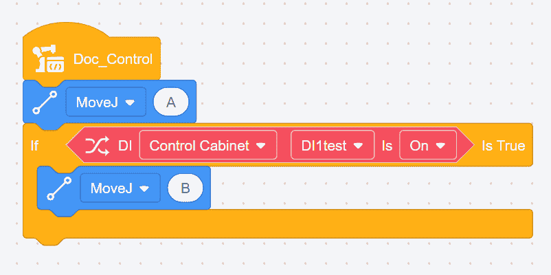
- If... True: This command is used to check whether the condition within the command is met. If the condition is met, the program inside the framework will execute; otherwise, it will not.
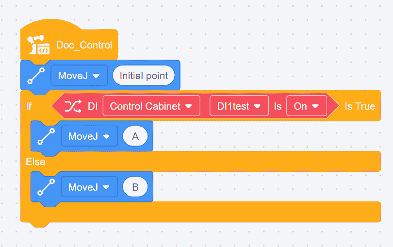
Example: If the current DI (Digital Input) is ON, the robot will move from point A to point B; if the current DI is OFF, the robot will only perform joint movement A.
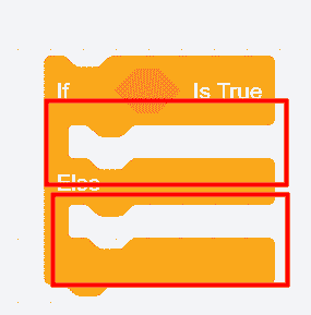
- If... True, Else: This command is used to check whether the condition within the command is met. If the condition is met, the program in region A will execute; if not, the program in region B will execute.
Example: If the current DI is ON, the robot will move to point A; otherwise, the robot will move to point B.
Palletizing Commands

Palletizing commands are primarily used for stacking items according to a specified pattern on a pallet. These commands need to be used in conjunction with loop commands.
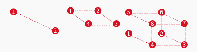
There are three types of pallet configurations: one-dimensional (line), two-dimensional (rectangle), and three-dimensional (cube). The trajectory diagrams are shown below:
Steps:
- Select
Pallet Type; - Set
SpeedAccelerationStop at Point or Transition with Arc
Conveyor Tracking Commands
These commands enable the robot's end effector to follow a conveyor belt and perform actions in real time. Before using conveyor tracking in software, the environment must be set up, including connecting the encoder to the control cabinet and establishing a Modbus TCP connection between Modbus poll and the robot. There are four types of conveyor tracking:
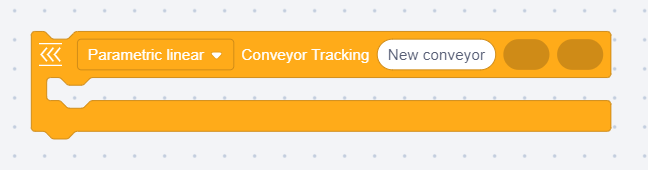
Linear Conveyor Tracking
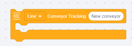
- Drag motion commands (not joint motion) into the conveyor tracking instruction block. The starting position of this command is where the robot motion begins.
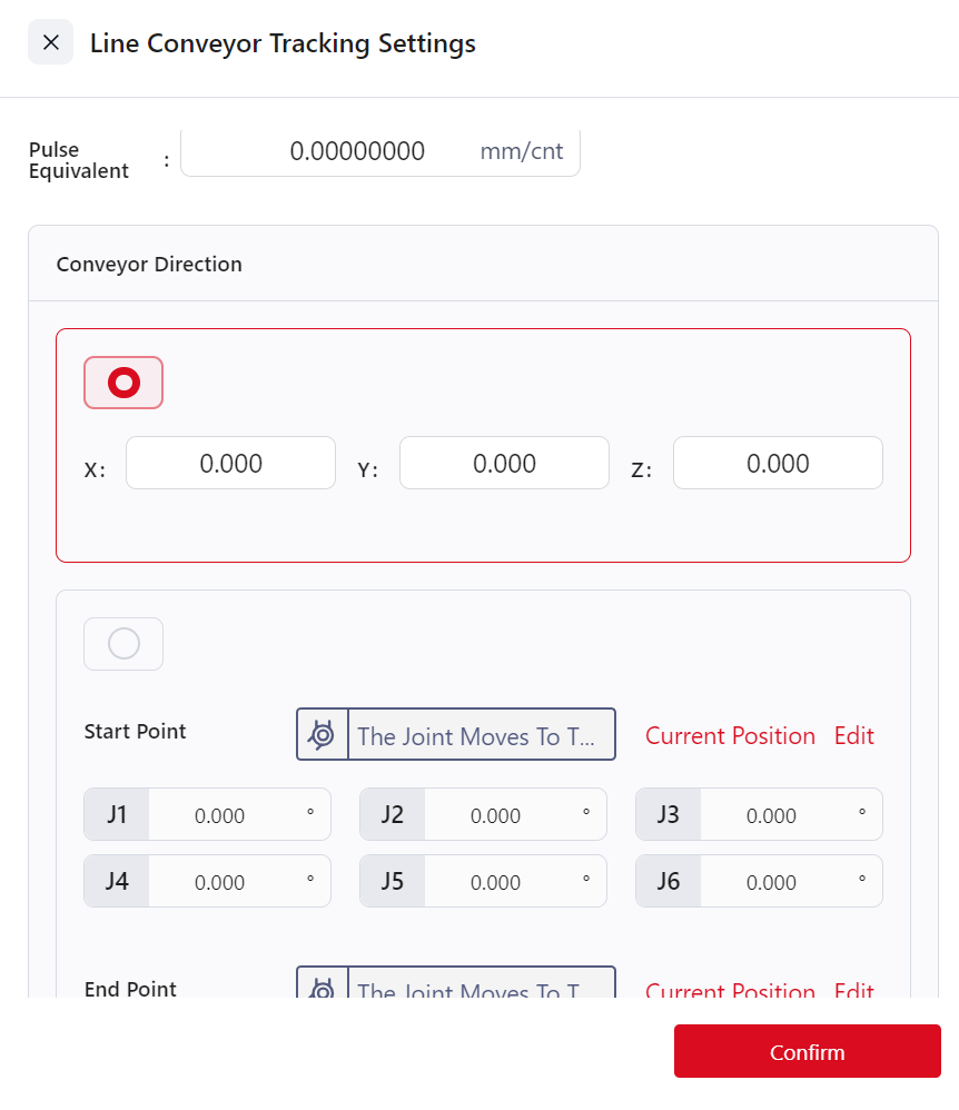
- Calculate
Pulse Equivalent: Measure the distance traveled by the conveyor and the change in encoder pulses, then calculate the pulse equivalent. (Use calipers for distance measurement and Modbus for pulse count.) The calculation formula is:
Pulse Equivalent = Distance (mm)/ Pulse Count (cnt)
Set
Conveyor Direction- Manual Input:Define the conveyor direction in the user coordinate system by specifying the direction from [0,0,0] to [X,Y,Z]. For example, [1,0,0] indicates movement along the X-axis of the user coordinate system.
- Start and End Points:Specify the conveyor direction based on two points. The system will calculate the movement direction automatically, with the conveyor direction pointing from the start to the end point.
The coordinates of the start and end points are relative to the world coordinate system.
Set
Tracking Accuracy Compensation:Compensate for discrepancies between the actual and taught positions, with a range of ±100 mm. Enter the measured offset into the compensation input box.Set
Maximum Tracking Distance:Define the maximum distance the robot can move from the starting to the ending position, limiting the robot's range of motion. The range is 1–3000 mm. Enter the value based on the conveyor length, the robot's starting and ending positions, and its arm reach. If the robot exceeds this limit, it will stop.Set
Start Tracking Distance:Define the distance from the robot's starting point to where it begins tracking the conveyor. The range is 0–3000 mm. Enter the value in the "Start Tracking Distance" field.
Dynamic Linear Conveyor Tracking
Dynamic linear conveyor tracking is based on linear conveyor tracking but uses variable assignments for the start and end points. Drag position variables or array variables into the oval input fields to define these points. Other settings remain the same as in linear conveyor tracking.
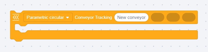
Circular Conveyor Tracking

- Drag motion commands (not joint motion) into the conveyor tracking instruction block. The starting position of this command is where the robot motion begins.
- Calculate
Pulse Equivalent: Measure the conveyor's travel distance and the change in encoder pulses, then calculate the pulse equivalent.
Pulse Equivalent = Distance (mm) / Pulse Count (cnt)
Configure
Tool Orientation:- Tool Orientation changes: The end effector rotates along the conveyor's axis during tracking.
- Tool Orientation Fixed: The end effector maintains a fixed orientation in the user coordinate system during tracking.
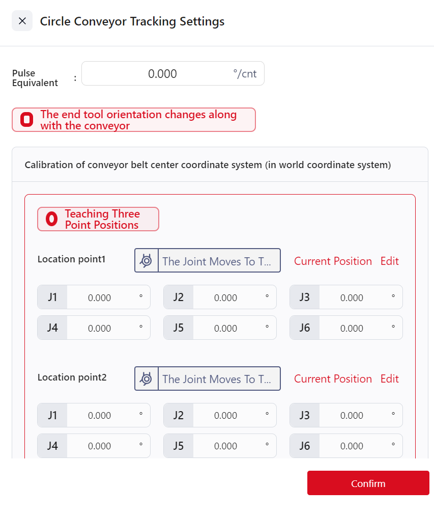
Calibrate Conveyor Center Coordinates:The center is defined by three points (P1, P2, P3) on the conveyor. These points can be taught or directly input relative to the world coordinate system.Teaching Three Points:- Identify a point P on the conveyor belt, rotate the conveyor so that point P moves into the robot’s workspace.
- Click the command to enter the circular conveyor tracking settings interface, select position point 1, and enter the motion control interface. Move the robot so that the tool's end aligns with point P (note: the user coordinate system must be set to "World"). Then click "Confirm" to complete the teaching of position point 1.
- Lift the robot tool and rotate the conveyor in its motion direction to a certain angle.
- In the circular conveyor tracking settings interface, select position point 2, enter the motion control interface, and again move the robot tool’s end to align with point P (note: the user coordinate system must still be "World"). Then click "Confirm" to complete the teaching of position point 2.
- Lift the robot tool again and rotate the conveyor further in its motion direction to another angle.
- In the circular conveyor tracking settings interface, select position point 3, enter the motion control interface, and again move the robot tool’s end to align with point P (note: the user coordinate system must still be "World"). Then click "Confirm" to complete the teaching of position point 3.
- Click "Confirm" in the circular conveyor tracking settings interface to finalize the calibration of the conveyor’s circular center coordinate system.
Input Three Points:Directly input the coordinates of the three points.
Set
Tracking Accuracy Compensation:Used to compensate for discrepancies between the actual position and the taught position, with a range of ±100 mm. To use, measure the deviation between the actual tracked position and the taught position, then input the deviation value into the “Tracking Accuracy Compensation” field.Set
Maximum Tracking Distance:This parameter defines the distance between the robot's starting point and the endpoint of its movement. It is used to restrict the range of the robot's end-effector, preventing it from exceeding the conveyor belt's range or reaching singularities. The valid range is 1~3000 mm. To configure, determine the parameter value based on the actual length of the conveyor belt, the robot's starting position, its endpoint, and the robot's arm reach. Check the box next to "Track Maximum Distance," and enter the range value in the input field. If the robot exceeds this limit, its movement will stop.
Dynamic Circular Conveyor Tracking
Dynamic Circular Conveyor Tracking builds upon the Circular Conveyor Tracking feature, modifying the configuration of Position Point 1, Position Point 2, and Position Point 3 to use variable assignments. Position variables or array variables can be dragged into the elliptical frame to serve as Position Point 1, Position Point 2, and Position Point 3 for the conveyor. Other setup steps are the same as those for Circular Conveyor Tracking.
Conveyor Queue Enable Digital Input
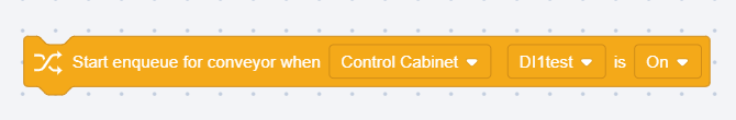
This instruction is used to obtain and store the material positions on the conveyor belt, preventing material loss due to the high speed of the conveyor belt and the robot being unable to process every piece of material in time. This instruction needs to be used in conjunction with the “Conveyor Belt Queue Retrieval” instruction. After using this instruction, the material position information on the conveyor belt is recorded in the controller. When the program runs the “Conveyor Belt Queue Retrieval” instruction, the stored material position information is retrieved in the order it was stored.
The digital input source comes from the I/O interface connected to the sensor or vision device that identifies the material information.
Conveyor Belt Queue Retrieval

This instruction is used to read the stored conveyor belt material position information.
Clear Conveyor Queue
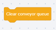
This instruction is used to clear the stored conveyor belt material position information.
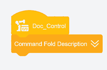
Command Fold
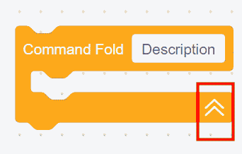

This command enables the collapsing of all commands within its frame into a single command.
Clicking anywhere on this command will trigger the folding effect. The arrow direction on the command indicates whether it is in a folded state (upward arrow) or an unfolded state (downward arrow).
Example: Folding the commands as shown below.

Log Output Type and Content

This command allows users to customize log output at specific points in the program.
Select the Log Type from the dropdown menu, and enter values or drag in string variables into the Log Content field. The output log can be viewed in the Log Information section.
Example: Output log content pos1 and pos2 when reaching a specified position.

Program Stop or Pause

This command can be added at any point in the program to stop or pause the program at that location.
Multithreading Commands
Program Execution
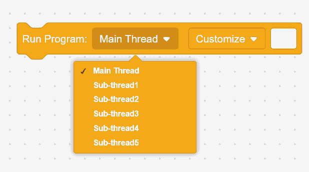
This command allows the main program to call other programs and set them as either the main thread or a sub-thread.
If set as the main thread, the main program will switch to execute the program file specified by this command and will only return to continue executing the subsequent commands once the program is complete. This is sequential execution.
If set as a sub-thread, the main program will create an independent, parallel thread upon reaching this command, allowing the sub-thread to execute its specified program file while the main program continues to execute subsequent commands. This is parallel execution. A maximum of 5 sub-threads can be created to run concurrently with the main program. Sub-threads will terminate when the main program ends.
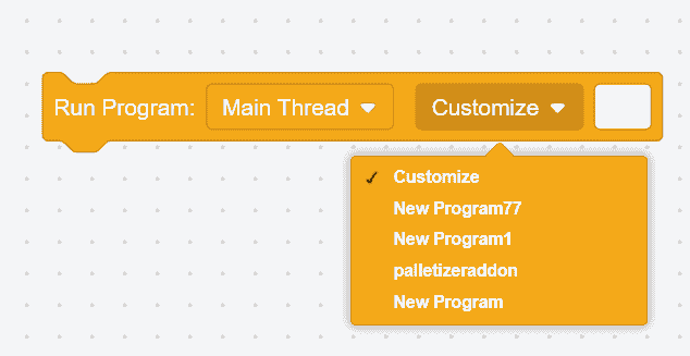
Select the content to be executed by the main thread or sub-thread here. If Customize is selected, the location of the program file to be called must be entered in the white box.
Example: The first command executes the program file named "speed" as a main thread, and the second command executes the program file named "testing" as a sub-thread.

Thread Operations
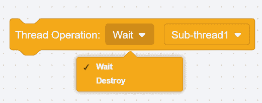
As shown in the figure above, there are two types of thread operations:
Wait: When the program reaches this command, it will pause and wait for the program within this command to complete before continuing with subsequent commands.
Destroy: When the program reaches this command, it will terminate the program within the command and continue with the subsequent program.
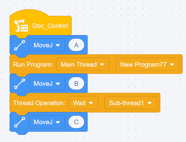
Example - Wait: After the robot moves to point A, it executes the sub-thread "testing" and simultaneously moves to point B. The robot waits for the sub-thread "testing" to complete before moving to point C.
Example - Destroy: After the robot moves to point A, it executes the sub-thread "testing" and simultaneously moves to point B. The sub-thread "testing" is terminated, and the robot continues moving to point C.

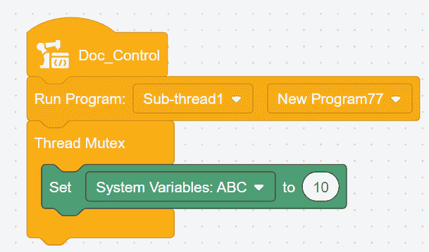
Thread Mutex Support

When a main program has multiple sub-programs, and different sub-programs contain identical commands, the thread mutex command can prevent conflicts between these commands. By placing identical commands within a thread mutex command block, simultaneous execution of these identical commands is prevented, avoiding program errors.
The execution order of identical commands is as follows: the command that starts first will execute, while other identical commands will wait until the ongoing identical command completes its execution.
Warning:
This command is only effective for variables.
Example: Insert sub-thread 1 into the main thread, and if sub-thread 1 also contains a command to set the system variable ABC, to avoid conflicts, the setting of the system variable ABC can be placed within a thread mutex support command block.
Smooth Transition Time

The maximum duration of this command is 1 second. During the smoothing transition period, force limits are temporarily increased, which helps mitigate robot jerkiness when switching payloads.
Enable Vibration Suppression Frequency
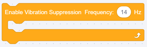
This command is disabled globally by default. It only takes effect after the Vibration Suppression function is enabled in the System Parameters under Maintenance Mode.
Frequency range: 0–20 Hz.
Calculations
Arithmetic Operators

Six arithmetic operations are provided: addition (+), subtraction (-), multiplication (*), division (/), modulus (%), and exponentiation (**).
Mathematical Function Calculations
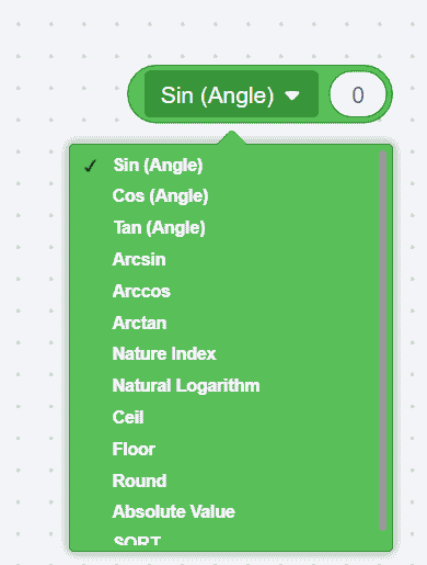
Mathematical function calculations include sine, cosine, tangent, arcsine, arccosine, arctangent, natural exponent, natural logarithm, ceiling, floor, rounding, absolute value, and square root.
Comparison Operators
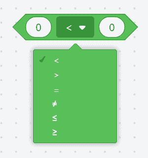
Comparison operators provided include: less than, equal to, greater than, not equal to, less than or equal to, and greater than or equal to. When conditions are met, the result returned is true.
AND

If both conditions within the diamond-shaped box are true, the result returned is true.
OR

If both or either of the conditions within the diamond-shaped box are true, the result returned is true.
XOR

If only one of the conditions within the diamond-shaped box is true, the result returned is true.
NOT

If the condition within the diamond-shaped box is false, the result returned is true.
Position Calculations
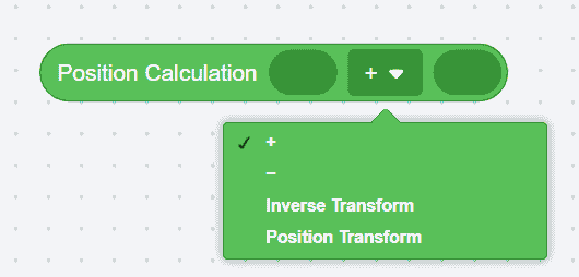
Add or subtract two positions.
Inverse Transformation:This refers to matrix inversion. The position is calculated using Cartesian coordinates.
- For example: Set point P, with coordinates (10,10,10,10,10,10), its inverse transformation position would be (-10,-10,-10,-10,-10,-10).
Position Transformation:Position variables or taught points can be dragged into the frame. Drag the initial pose into
Position Calculation, and the incremental transformation of the robot's relative pose intoPosition Transformation. The return value of the command is the result of the transformation.
Position Distance

Position variables or taught points can be dragged into the frame. The return value of the command is the Cartesian distance between two positions.
Interpolation Point
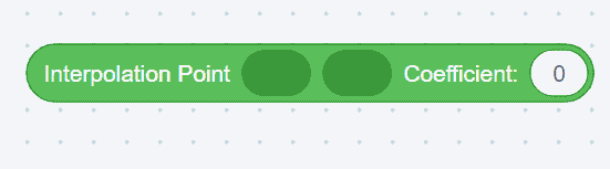
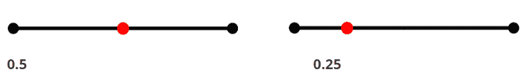
This command calculates an interpolation point between two points based on a given coefficient, which ranges from 0 to 1. Position variables or taught points can be dragged into the frame, and the return value of the command is the position of the interpolation point.
Example: Setting the coefficient to 0.5 or 0.25 will position the interpolation point at the red point shown in the image below:
Plane Transform
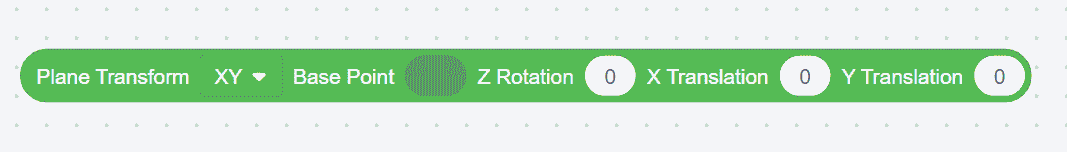
This command is used to transform a point within the XY, YZ, or ZX planes. The transformation involves rotating around the Z, X, or Y axis at the base point, followed by translation along the X, Y, or Z axis.
Position variables, array variables, or taught points can be dragged into the base point. The return value of the command is the transformed pose.
Example: First, translate point P along the user coordinate system's direction by (0,10,10), then rotate point P around the X-axis of the user coordinate system by 10°.

Inverse/Forward Kinematics
- Inverse Kinematics
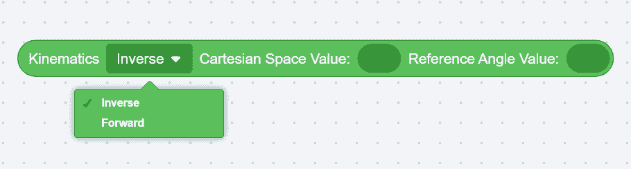
Using this command, input Cartesian space values to calculate joint angle values.
- Forward Kinematics
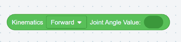
Using this command, input joint angle values to calculate Cartesian space values.
String Operations
Note:
Supported escape characters in string commands include \、'、''、\n、\t、\r,corresponding to the backslash symbol, single quote, double quote, newline, horizontal tab, and carriage return, respectively.
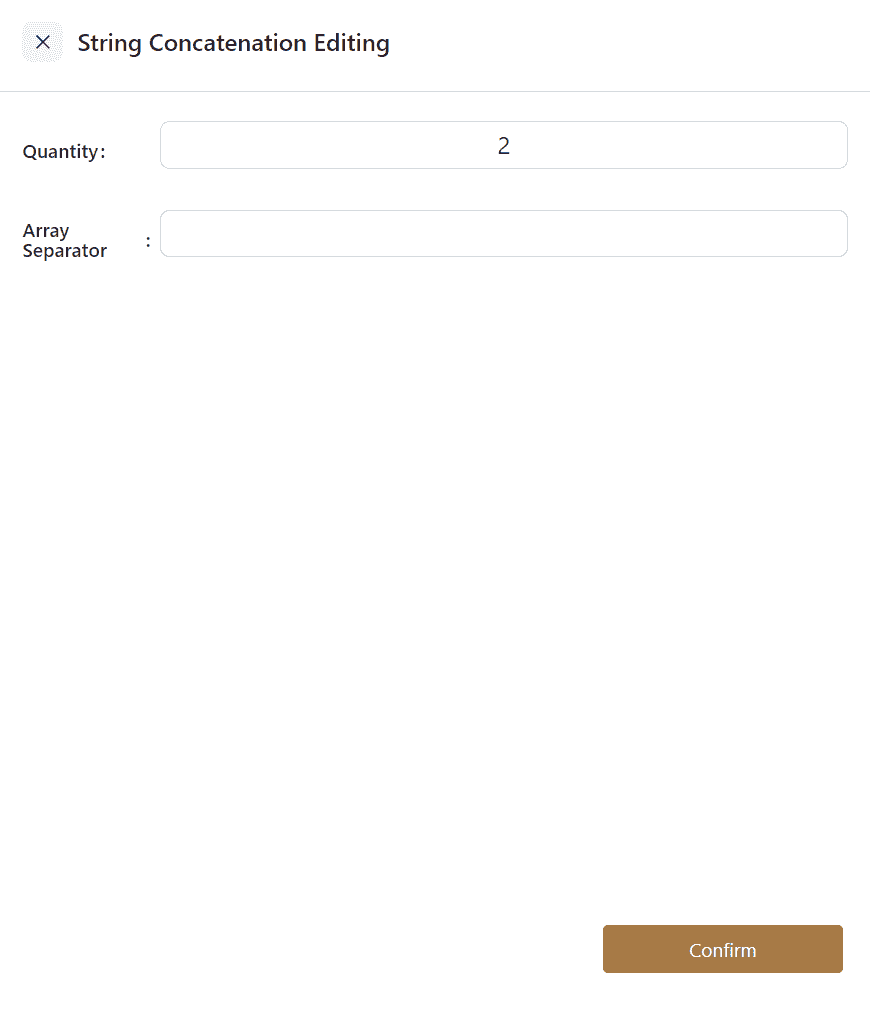
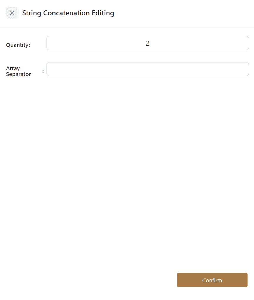
String Concatenate

This command concatenates variables or input strings. It returns the concatenated string as a string variable.
Clicking on this command opens an editor where the number of white oval frames (up to 8) and the required array delimiter can be set.

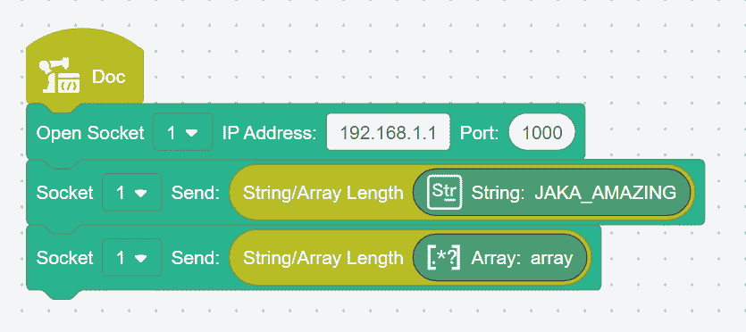
String/Array Length

This command calculates and returns the length of a string or array.
String variables, array variables, or direct string inputs can be dragged into the command.
Example: The host computer needs to obtain the length of the string variable "JAKA_AMAZING", which is 12, or the length of the array variable [1,2,3,4,5,6], which is 6.
String Compare

This command compares two strings based on their ASCII values.
String variables or string values (str1, str2) can be dragged into the command.
If str1 = str2, the return value is 0.
If str1 < str2, the return value is negative.
If str1 > str2, the return value is positive.
- Example: Compare the sizes of string variables str1 and str2, with the return value being negative.

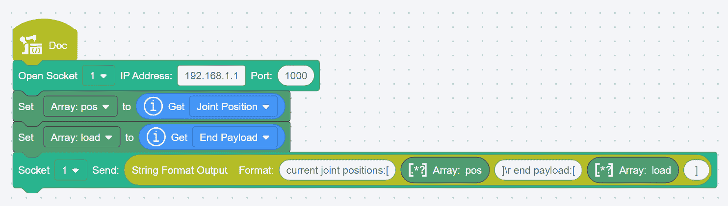
String Format Output

This command formats specified data into a string according to the specified format. The return value is a formatted string variable.
Clicking on this command opens an editor where the number of white oval frames (up to 8) and the required array delimiter can be set.
- Example: Retrieve the robot joint information: current joint positions:[0,90,0,90,180,0], end payload:[0,0,0,0].
String Format Input

This command matches a string in a specific format and inputs the matched data into the specified variables. The formatted result can be assigned to integer, floating-point, or string type variables or constants.
Clicking on this command opens an editor where the number of white oval frames (up to 8) and the required array delimiter can be set.
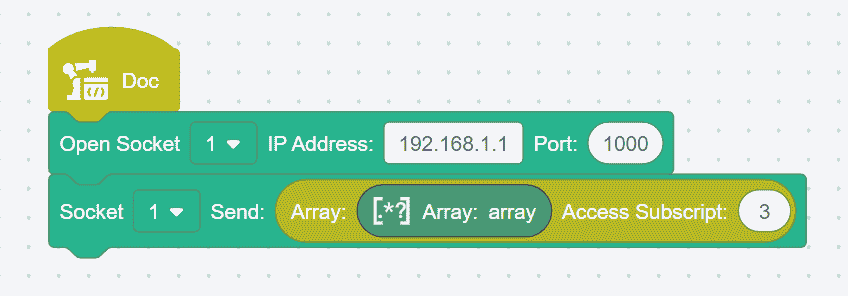
Convert Array to String

This command converts an array into a formatted string variable.
Drag the array variable to be converted into the
Arrayfield, and enter the string delimiter in theDelimiterfield.
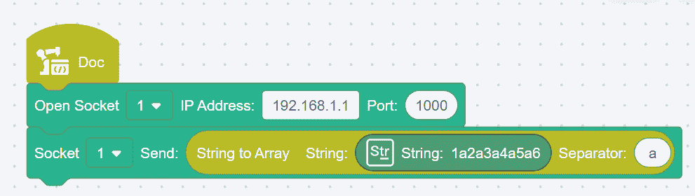
Convert String to Array

This command converts a string in a specific format into an array variable.
Drag or input the string variable to be converted into the
Stringfield, and input the string delimiter in the Delimiter fieldExample: Convert the string variable "1a2a3a4a5a6" into the array variable [1,2,3,4,5,6].
Array Index Access
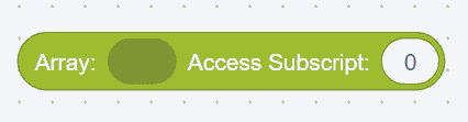
This command allows you to access a specific variable in an array by setting the
Index.Drag the array variable to be accessed into the field and input the index value to be accessed. The index starts from 0. The command returns the accessed element.
Example: Access the value at index 3 in the array variable [1,2,3,4,5,6], which returns the value 4.
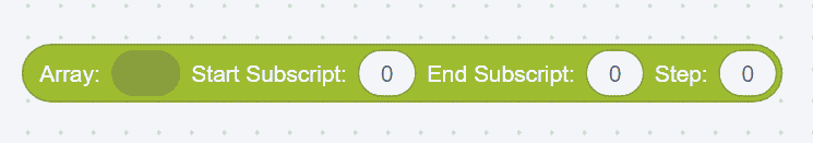
This command allows you to access elements in an array based on the required index and step value.
Drag the array variable to be accessed into the field, and input the index value and step value to be accessed. The index starts from 0. The command returns the accessed sub-array.
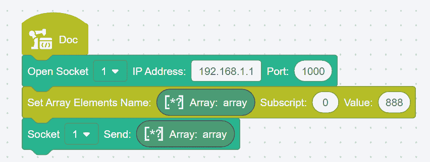
Set Array Elements
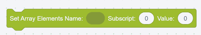
This command allows you to set the value of a specific element in an array.
Drag the array variable to be set into the field, and input the index value of the element to be set. The index starts from 0.
Example: Set the value at index 0 in the array variable [1,2,3,4,5,6] to 888, changing the array variable to [888,2,3,4,5,6].
Communication Instructions
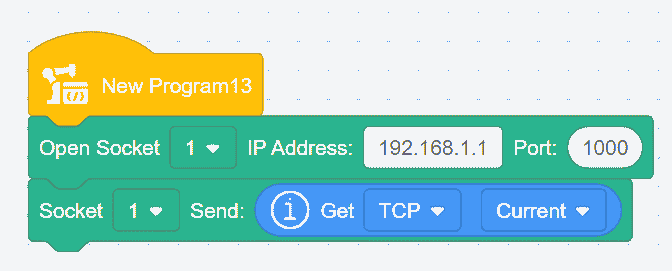
Open SOCKET

This command creates a TCP client and establishes communication with a TCP server.
Select the specified SOCKET ID from the drop-down list, input the TCP server's IP address and port number. Executing this command establishes a connection between the TCP client (robot) and the TCP server.
Open SOCKET and Return the Result

This command creates a TCP client, establishes communication with a TCP server, and returns the socket handle.
Select the specified SOCKET ID from the drop-down list, input the TCP server's IP address and port number. Executing this command establishes a connection between the TCP client (robot) and the TCP server, and a return value is obtained. If the connection is successful, a positive integer is returned; if the connection fails, the return value is -1.
Close SOCKET

This command disconnects a specified socket communication connection.
Select the specified SOCKET ID from the drop-down list. Executing this command will disconnect the specified socket communication connection.
SOCKET Send

This command allows the controller to send a variable to the TCP server via socket communication.
Select the specified SOCKET ID from the drop-down list. Drag in the variable or input a value. Upon execution, the TCP server will receive the content of this variable.
Note:
Supported variable types include numeric, string, and array. There are no specific format requirements for the data being sent, but Unicode characters are not supported
SOCKET Send with Return Result

This command allows the controller to send a variable to the TCP server via socket communication.
Select the specified SOCKET ID from the drop-down list. Drag in the variable or input a value. Upon execution, the TCP server will receive the content of this variable and a return value will be obtained. If the transmission is successful, the length of the sent data will be returned; if it fails, -1 will be returned.
SOCKET Receive Variable

This command represents waiting( ) seconds until a variable is received. The controller will send a data request string and then enter a waiting state.
Select the specified SOCKET ID from the drop-down list. Drag in the variable type to be received, and input the desired time in
Wait Time. If the variable is received within the ( ) seconds, or if the wait time exceeds ( ) seconds without receiving a variable, the program will proceed. If the set wait time is 0 seconds, the robot will wait indefinitely until the condition is met. This command does not support variable names containing Unicode characters.
Note:
Supported variable types for receiving include numeric, string, and array. The server’s data format should be as follows:
Numeric: <'Variable Name'><'Data Content'>
tring:<'Variable Name'><'Data Content'>
Array:<'Variable Name'><['Data Content']>
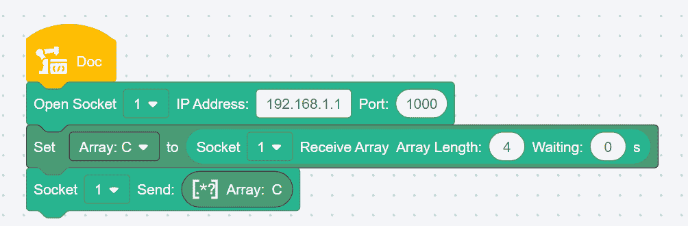
SOCKET Receive Array

This command makes the robot pause for ( ) seconds until an array variable of length ( ) is received. The controller will send a data request string and then enter a waiting state.
Select the specified SOCKET ID from the drop-down list.
If an array of equal or lesser length is received within the set time, the received array will be returned. Missing elements will default to FLOAT_MAX, where FLOAT_MAX = 340282346638528859811704183484516925440;
If the received array exceeds the set length, Coboπ will report an error and stop the program;
If the timeout is reached without receiving an array, an empty array will be returned, Coboπ will not report an error, and the program will continue;
If the wait time is set to 0, it indicates an indefinite wait, with a maximum wait time of 65,536 seconds, after which it will be treated as a timeout.
Note:
The server’s data format should be as follows: [n1, n2, n3...]
Example: Connect to the SOCKET server, receive array variable C and return the result, with an array length of 4.
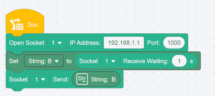
SOCKET Receive Data

This command makes the robot pause for ( ) seconds until data is received. When executing this command, the controller will not send any additional data.
Select the specified SOCKET ID from the drop-down list. If data is received within ( ) seconds, or if the wait time exceeds ( ) seconds without receiving data, the program will continue (if the wait time is set to 0 seconds, the robot will wait indefinitely until the condition is met);
If received successfully, the function returns the received string;
If receiving fails or times out, an empty string is returned.
Note:
The received variable type is a string. There are no specific format requirements for the server’s data, but Unicode characters are not supported.
- Example: Connect to the SOCKET server, receive program variable B, and return the result.
Refresh Semaphores

This command refreshes the semaphores defined under
SettingsHardware & CommunicationEnd I/O.Select the semaphore to be refreshed from the drop-down list and input the refresh rate (in Hz).
The refresh rate is limited by the bus bandwidth; the total refresh rate of all signals should not exceed 125 Hz. The system will automatically schedule the refresh.
Get Semaphore Status

This command retrieves the value of a semaphore.
Select the desired semaphore from the drop-down list. The command returns the current value of the semaphore.
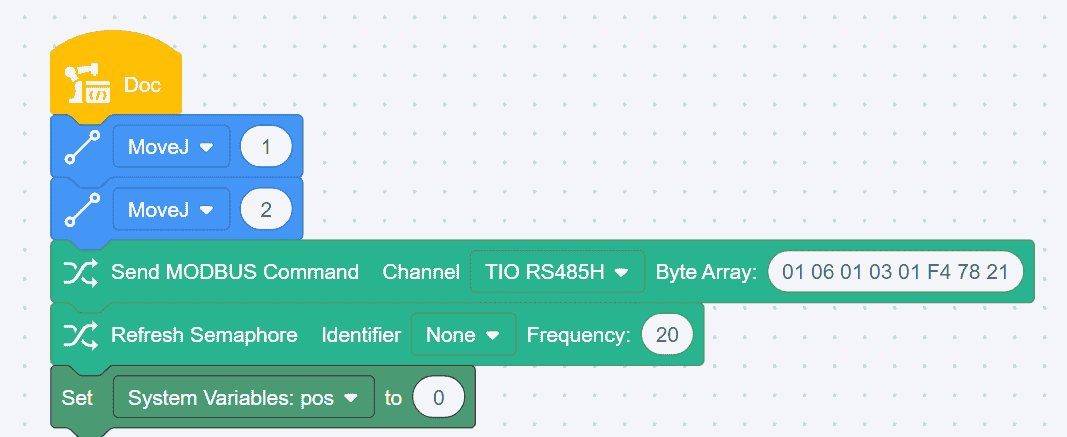
Send Modbus Command
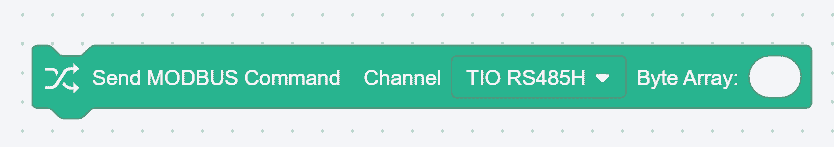
This command is for sending control commands to external TIO devices in a timely manner.
Select the TIO channel to be used from the drop-down list, and input the hexadecimal data command in the
Byte Arraysection. The user does not need to add a checksum, as the system will automatically include it.Example: Set the position of a device to 500 and retrieve the position message after setting.
Subprogram
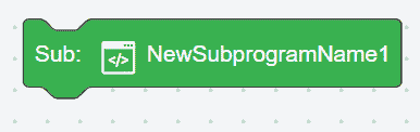
Users can add subprograms, which integrate multiple commands into a single entity for use in the main program. This helps streamline the display and improve processing speed.
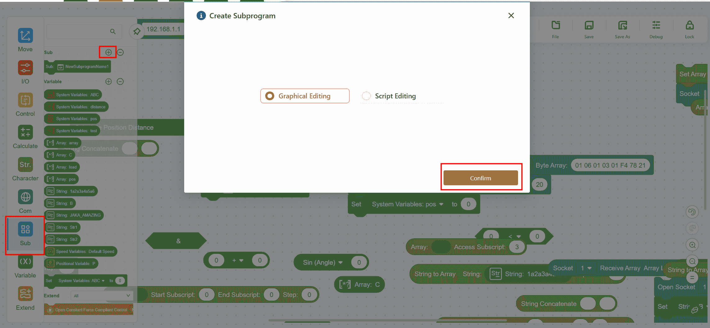
Adding a Subprogram
Open or save the main program first, then click Subprogram- +,in the command bar on the right. The Create Subprogram page will appear, where you can choose between Graphical Editing or Script Editing,as needed, then click Confirm.
Graphical Editing of Subprograms
The operation is the same as for the main program. After completing the command editing, be sure to click
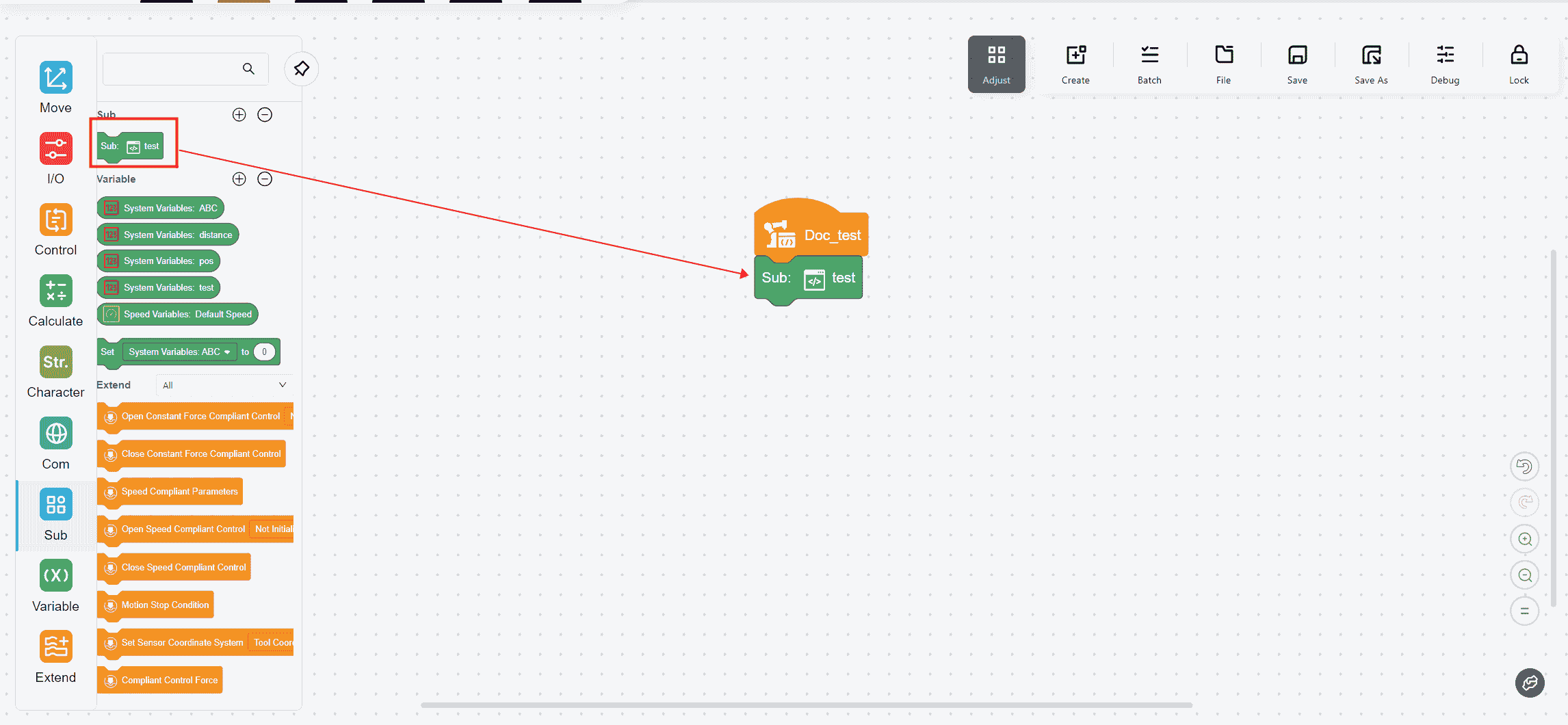
Save, then clickCloseto exit the subprogram editing page and return to the main program page.If the subprogram is successfully saved, the edited subprogram will appear in the
Subprogrambar. At this point, the subprogram acts as a single command and can be dragged into the main program for repeated use, just like any other command.
Script Editing of Subprograms
- The operation is the same as above. For specific script programming requirements, please refer to the JAKA Robot Script Manual.
Note:
To edit a subprogram, click the target subprogram box in the subprogram command bar or the main program to enter the subprogram editing interface.
After editing the subprogram, make sure to save the main program again to ensure that the subprogram is correctly updated in the main program.
In version 172, a new Main Program button has been added:

Clicking this button will instantly return to the main program page of the current subprogram.
Variables
Adding a Variable
To add a variable, click Variable - + in the command bar on the right. The Add Variable page will appear, allowing the user to select the desired variable type and add it by clicking Confirm.
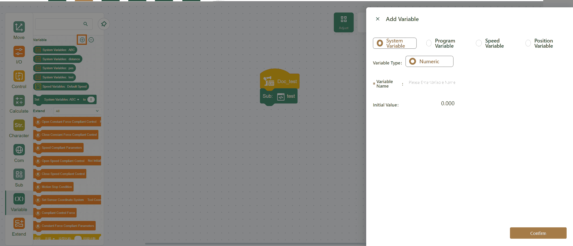
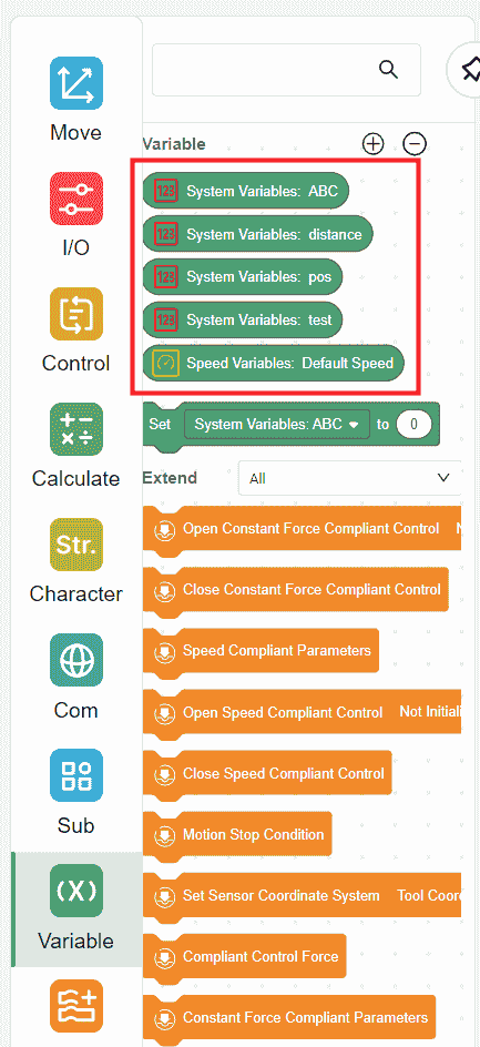
The added variable will appear in the command bar on the right.
System Variables
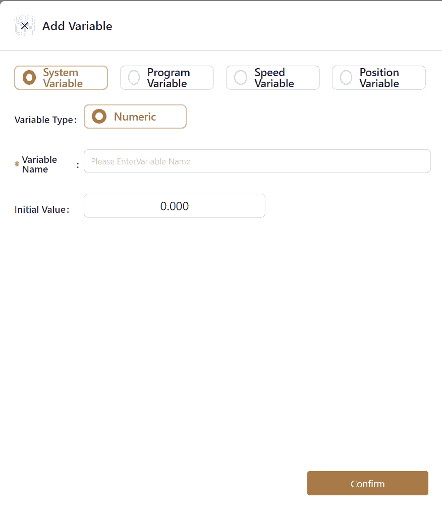
System variables are stored in the control cabinet. As a result, these variables are not cleared or removed when the robot is powered off or when a program is deleted. They can be accessed from any program.
Note:
In addition to the method described above, system variables can also be created and managed via Settings-Program Settings-System Variables.
Program Variables

Program variables are created for use within the currently open program and are only accessible within that program. If the current program is deleted, the variables are deleted as well.
There are three types of program variables: numeric, string, and array.
Program variable names can include Chinese characters. However, it is important to note that when communicating with third-party systems, Chinese character names may become garbled due to encoding issues.
Speed Variables
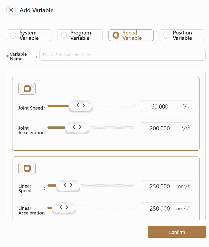
Speed variables are a special type of variable that can be toggled on or off using global speed-related commands within the Move section.
This command globally controls the robot's motion speed during program execution based on actual working conditions.
When a speed variable is called through a global speed command, all subsequent motions will adhere to the speed defined in the command, rendering speed settings within individual motion commands ineffective.
Similar to program variables, speed variables are only usable within the currently open program.
Note:
Speed variables can also be sent via SOCKET commands. The sent content includes joint speed, joint acceleration, linear speed, and linear acceleration.
Position Variables
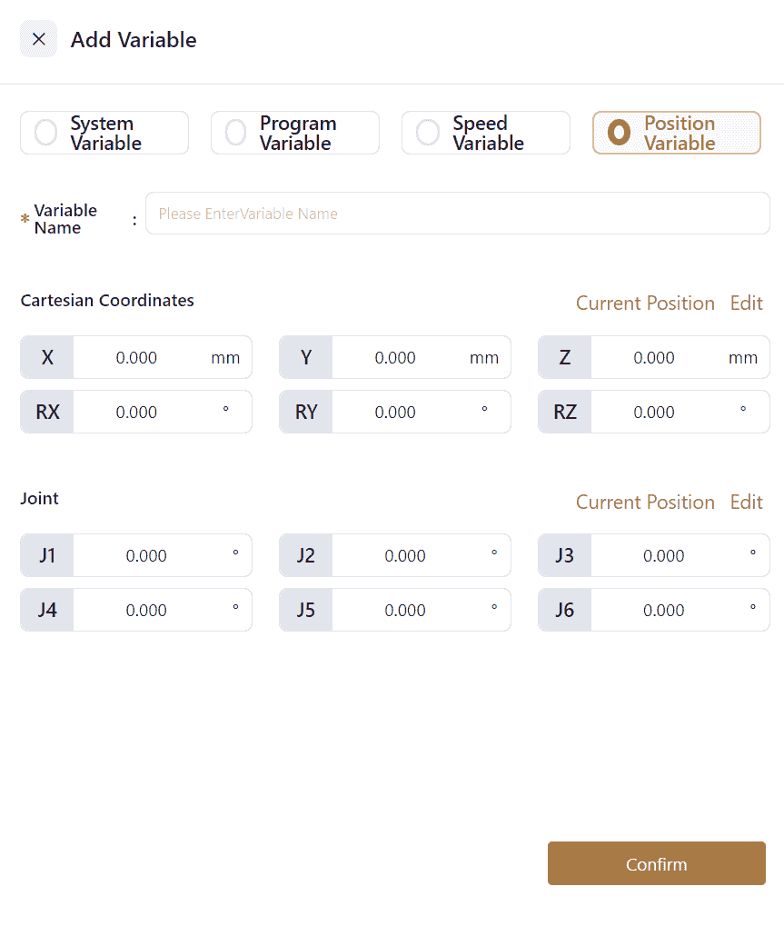
Position variables are used in motion commands or position calculation commands and cannot be called in other commands. Like program variables, position variables are only accessible within the currently open program.
Position variables can define the robot's Cartesian positions and joint positions. Values can be entered directly into the field or edited by clicking Edit to access the manual operation page for point teaching.
When setting Cartesian positions, pay attention to the coordinate system selection. If the chosen coordinate system does not match the actual setup, the robot's position may be offset, leading to safety risks.
If the Cartesian positions has changed, the value of joint angle would change accordingly.
When a position variable is placed in a motion command, the point information within the position variable is called, guiding the robot's movement.
Set Variable Command
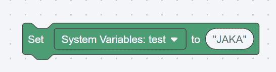
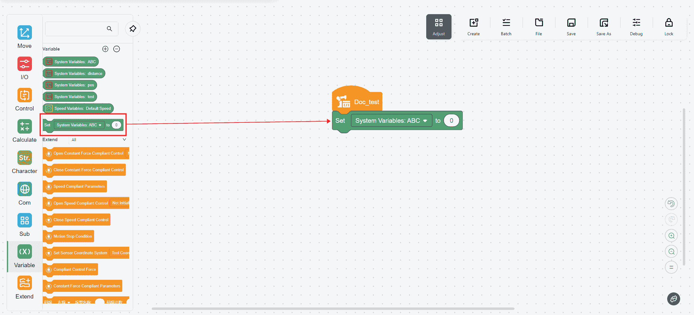
Drag the variable command from the left command bar into the operation page. Select the added variable type from the drop-down menu. Other operations are similar to other commands.
The white oval field allows the input of constants, variables, or values obtained via SOCKET.
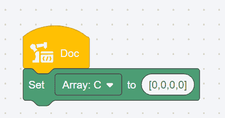
When assigning values to an entire array variable, enclose the specific values in square brackets [ ], as shown below:
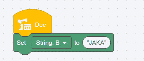
When assigning values to a string, enclose the content in double quotation marks "", as shown below:
Extend
These instructions must be used with JAKA force sensor
Constant
Constant Force Compliant Parameters
- Meaning: Set the compliance parameters in constant force mode.
- Usage: Choose the direction in which you need to enable the force control, set the damping force, rebound and constant force in each direction, and choose whether to enable directional tracking.
- Damping force: When the program is executed, the greater the external environment stiffness, the greater the damping force needs to be set; in drag mode, it is recommended that Fx, Fy, and Fz be greater than 10N, and Mx, My, and Mz be greater than 0.2 Nm. The setting value cannot be 0.
- Rebound:Let the robot return to the preset trajectory. The larger the setting value, the more difficult it is for the robot to deviate from the preset trajectory.
- Constant force: The contact force between the robot end and the external environment is within the set constant force value.

Open constant force compliant control
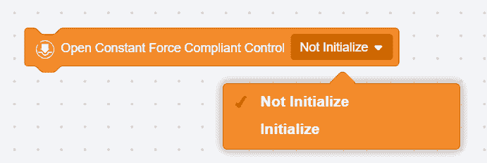
- Initialize: Compensate for the sensor's bias and load, etc. (make sure the sensor is not in contact with external forces when entering this mode).
- Do not initialize: Use the previous compensation value.
Close constant force compliant control

Close constant force control
Speed Compliant Control
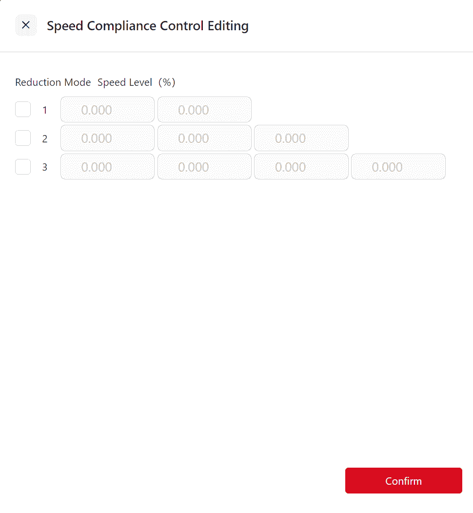
Speed Compliant Parameters

- Meaning: Set the compliance parameters in speed mode.
- Usage: Configure the deceleration level , up to three levels of deceleration can be configured. When the force on the end of the robot is greater than the control force setting value, the robot will decelerate until the sensor detection value is less than the control force setting value. The user can set the percentage of each deceleration to the original speed.
Open Speed Compliant Control

Open Speed Compliant Control and select whether to initialize.
- Initialize: Compensate for the sensor's bias and load, etc. (make sure the sensor is not in contact with external forces when entering this mode).
- Do not initialize: Use the previous compensation value.
Close Speed Compliant Control

Close Speed Compliant Control Mode.
Compliant Control Force

Used to set the control force in force control mode.

Motion Stop Condition

- Meaning: Set conditions for end of motion
- Usage: Check the direction to be monitored and set the upper or lower limit; when the contact force value is less than the lower limit or greater than the upper limit, the motion termination condition is triggered. This instruction monitors the next motion instruction. If the motion termination condition is triggered, the robot will immediately move from the current position to the set position of the next motion instruction.

Set Sensor Coordinate System
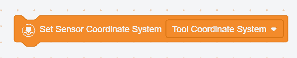
- Meaning: Set the coordinate system used in force control mode (the direction of the coordinate system must be consistent with the direction of the sensor).
- Usage: Select the tool coordinate system, the robot end position relative to the tool coordinate system; select the world coordinate system, the robot end position relative to the robot base coordinate system.