Manual Control
Manual Control

Clicking this icon opens the manual control interface.
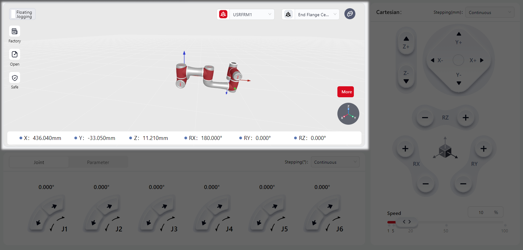
The manual control interface is divided into three main functional areas: the Simulation Model Area, the Operation Area, and the Floating Jogging Area, as shown below.
Simulation Model Area
The specific functions in this area include:
Floating Jogging Button
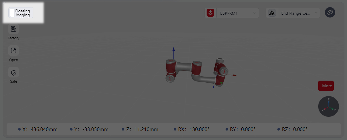
Clicking this button enables the floating jogging mode. Detailed function can be found in the Floating Jogging Area.
Pose Quick Restore Buttons
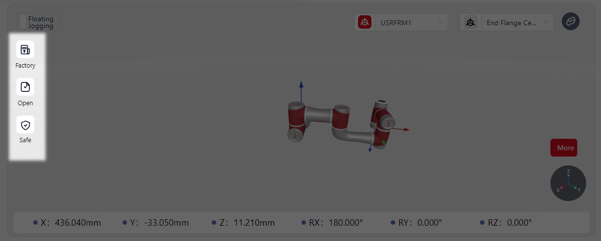
Press and hold any of these three buttons to restore the robot to its Factory Pose, Open Pose and Safe Pose.
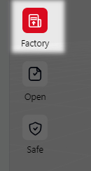
When holding the button, it turns red, indicating that the robot is moving. The robot stops moving when it reaches the selected orientation.
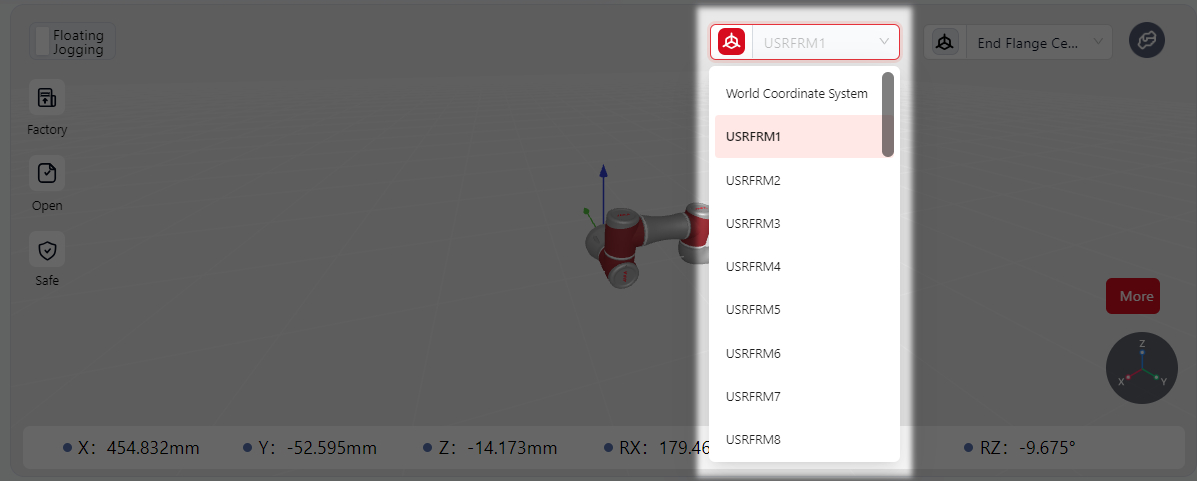
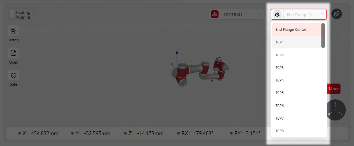
Coordinate System Switch
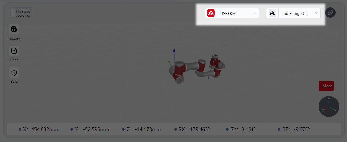
This option allows switching between the World (User) Coordinate System and the Tool Coordinate System when the robot moves in Cartesian space.
When the icon is red, it indicates that the selected coordinate system is active. Clicking the drop-down box allows the selection of different World (User) Coordinate Systems and Tool Coordinate Systems (settings for these coordinate systems are detailed in the Settings interface).
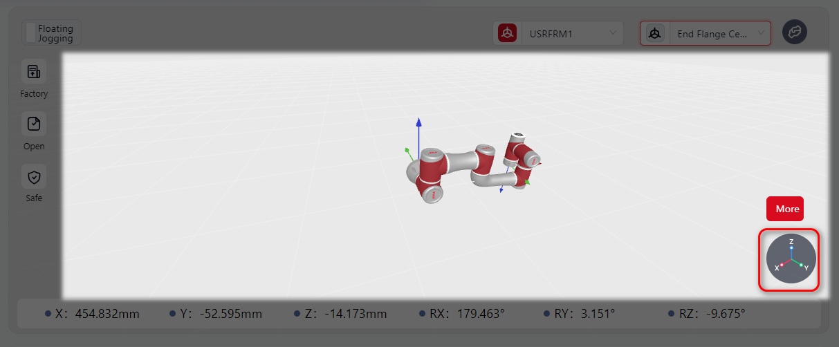
Simulation Model Display Area
The 3D model in this area matches the real or simulation robot in use and shows the robot's real-time movement or simulated movement.
Hovering the mouse in this area and scrolling the mouse wheel will zoom in or out for a better view of the robot’s overall structure or details.
Hovering and holding the left mouse button while moving the mouse allows changing the viewpoint direction, making it easier to observe the robot from a 360° perspective.
The circular icon in the lower right corner displays the X, Y, and Z axes, helping to clarify the robot's current movement direction.
Parameter Display Area
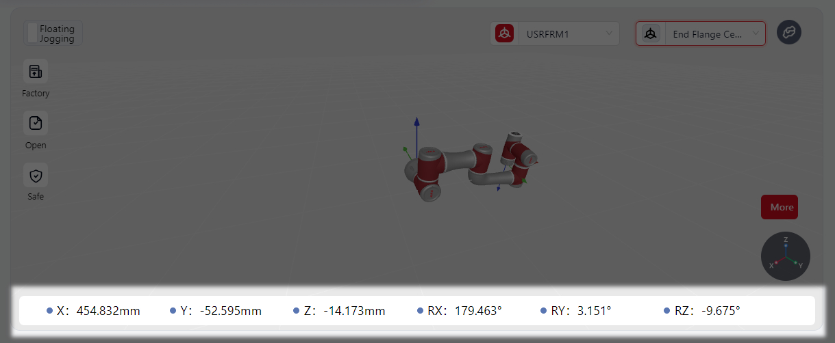
This area shows the pose of the tool coordinate system within the world (user) coordinate system when the physical robot or model is in motion.
Operation Area
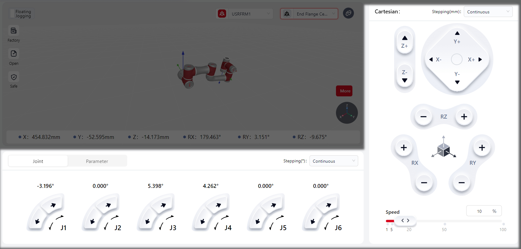
In this area, the robot can be controlled through Spatial Adjustment、Joint Adjustment and Parameter Adjustment methods.
- In Version 172, the default speed in the manual operation area is 10%:
When navigating to the manual operation page from other sections (e.g., programming page), the speed remains set to 10% by default.
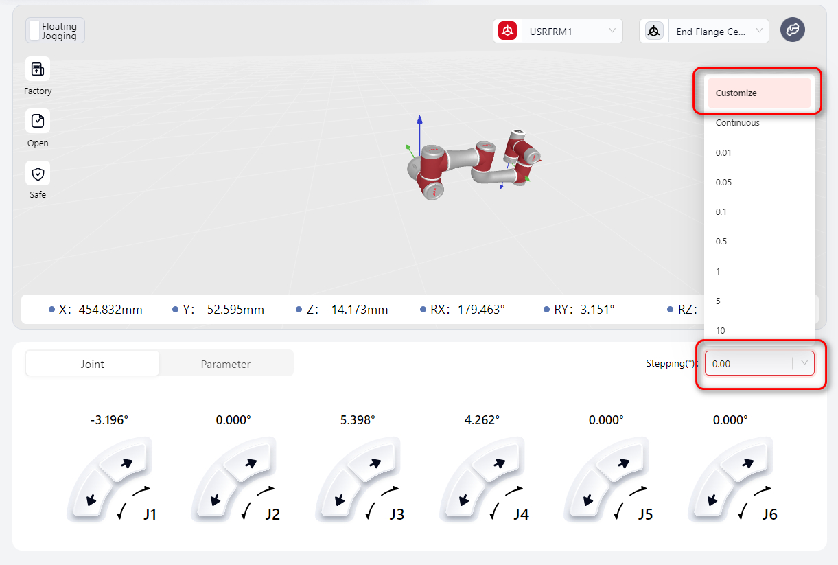
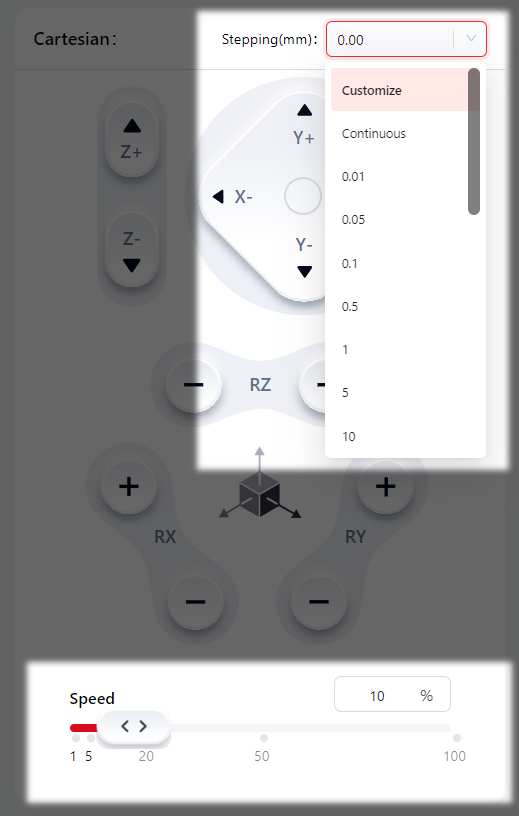
- Version 172 supports the
Customizefeature.
After selecting Customize users can input a value in the input field (only numbers and decimals are allowed). The range is 0-100, with precision up to two decimal places:
- Version 172 introduces the
Reverse Drivefeature for Zu 20.
In this mode, the robot joint brakes are released, allowing the joints to be moved with minimal force.
In collision scenarios, the reverse drive feature enables selective release of specific joint brakes under robot-enabled status, moving the joint to the target position without releasing all robot brakes.
Click More, and the operation buttons will appear:
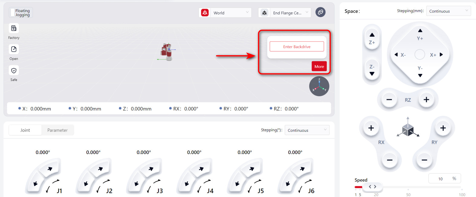
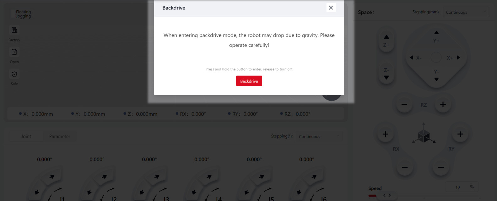
Press and hold Reverse Drive , and the robot enters reverse drive mode. Users can drag the desired joint to force its movement. Note:
The robot must be powered on and in an enabled state to enter reverse drive mode.
If the joint movement speed exceeds 50°/s during reverse drive mode, the system will exit reverse drive mode due to overspeed detection.
Warnings:
When the robot is in reverse drive mode, the released joint may rapidly fall due to gravity. Ensure effective support for the robot and any attached tools or workpieces before releasing the brakes.
- Version 172 introduces the
One-Key Posture Adjustmentfeature:
This feature enables quick adjustment of the robot flange to a specific angle. The operation steps are as follows:
Click More, and the operation buttons will appear:
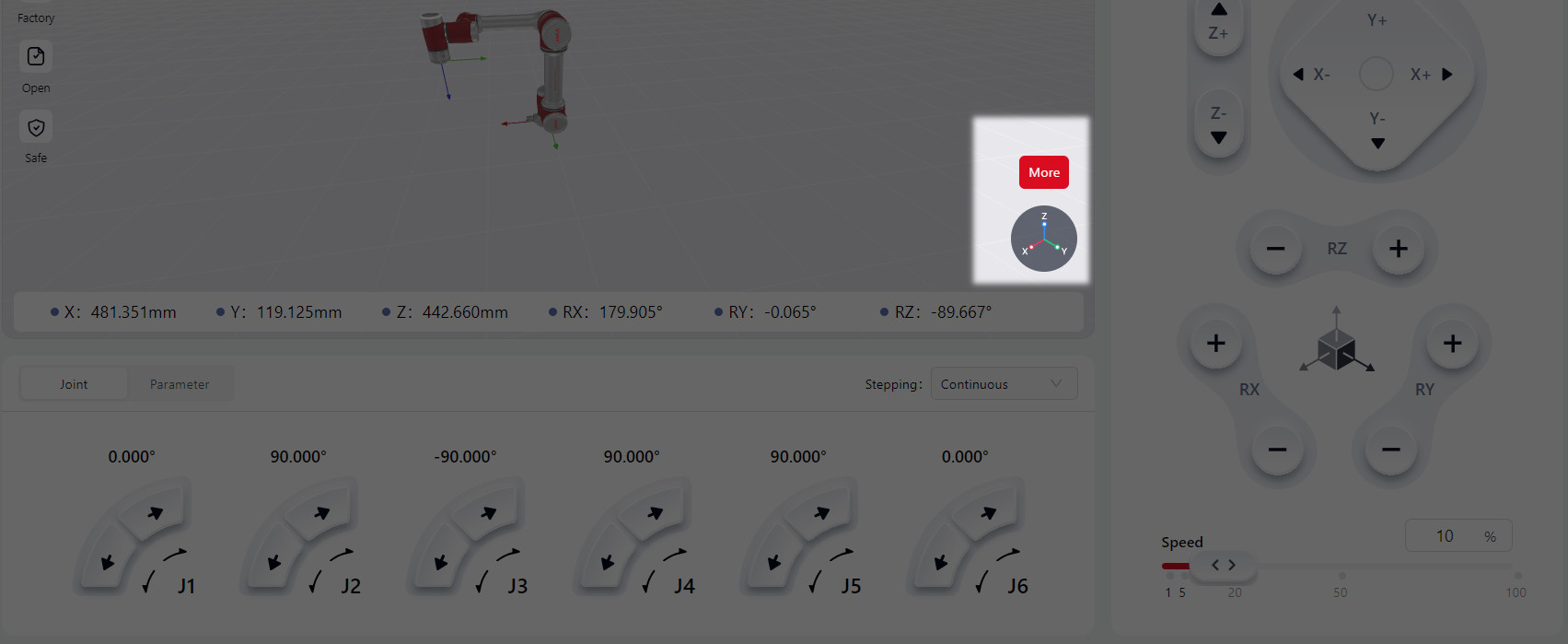
Click the X/Y/Z Axis button to switch the reference coordinate axis.
Press and hold the One-Key Align/One-Key Reverse button to adjust the robot flange posture. The selected coordinate axis of the flange coordinate system will align with the corresponding axis of the reference coordinate system.
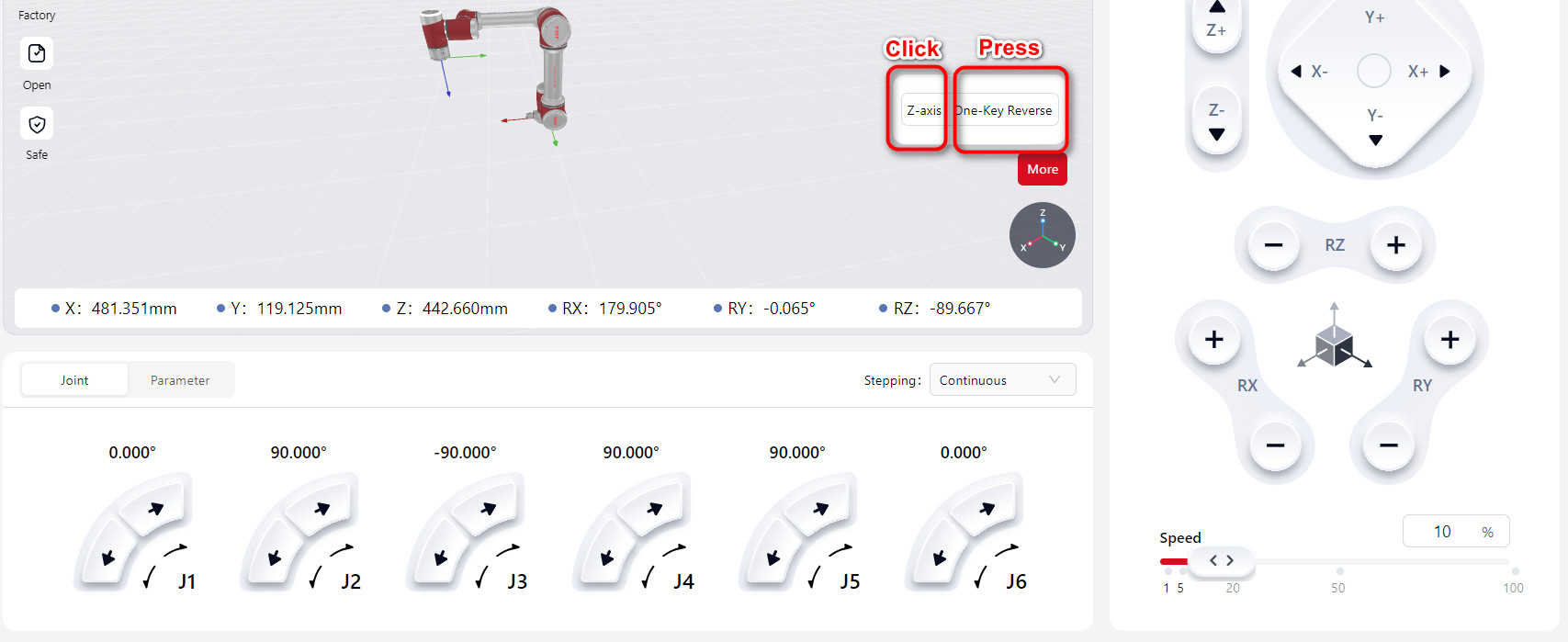
X/Y/Z Axis :X, Y, or Z axis of the reference and flange coordinate systems.
One-Key Align/One-Key Reverse : One-Key Align: Aligns the selected axis direction of the reference and flange coordinate systems. One-Key Reverse: Reverses the direction of the selected axis of the two systems.
Cartesian Space Adjustment
This involves controlling the Tool Coordinate System Origin of the robot within the World (User) Coordinate System (i.e., Cartesian space), allowing for either incremental or continuous motion.
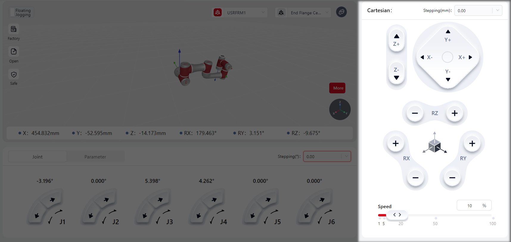
Pressing and holding or clicking the virtual joystick on the interface makes the joystick Red, indicating that the operation is active and the robot is in motion. Releasing the joystick turns it Grey, stopping the robot.
In the Stepping settings, continuous motion or specific incremental movements can be configured.
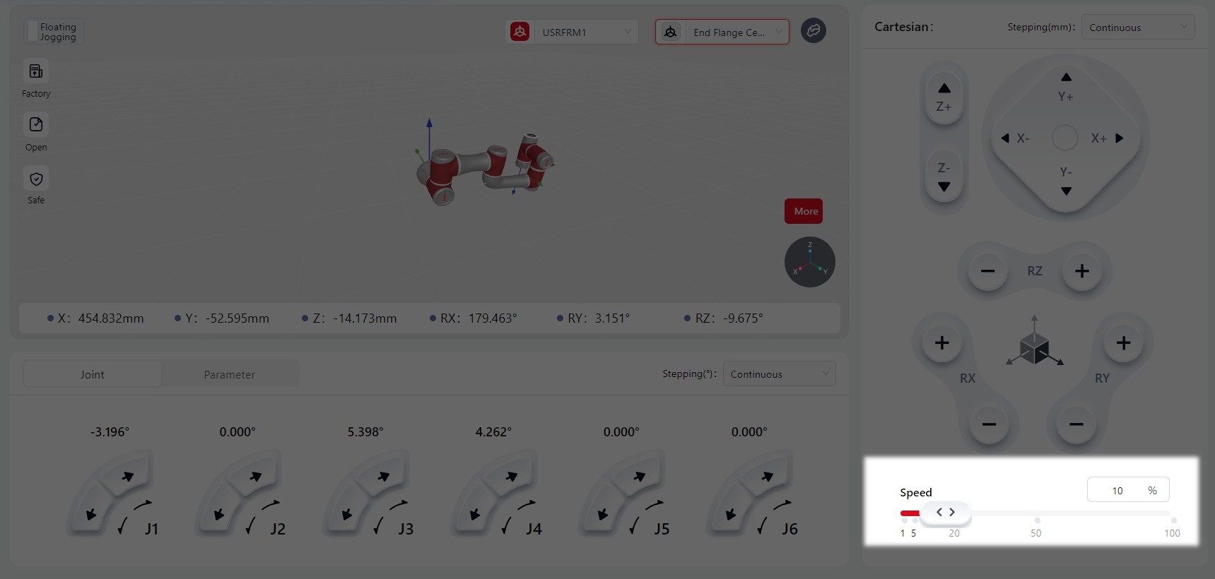
In the Speed settings, the robot's movement speed can be adjusted by dragging the slider or directly entering a value (1-100) in the box.
Joint Adjustment
This controls each joint of the robot independently for incremental or continuous motion.
Pressing and holding or clicking the virtual joystick on the interface makes the joystick Red, indicating that the operation is active and the robot is in motion. Releasing the joystick turns it Grey, stopping the robot.
In the Stepping settings, continuous motion or specific incremental movements can be configured.
In the Spatial Adjustment-Speed the robot's movement speed can be adjusted by dragging the slider or directly entering a value (1-100) in the box.
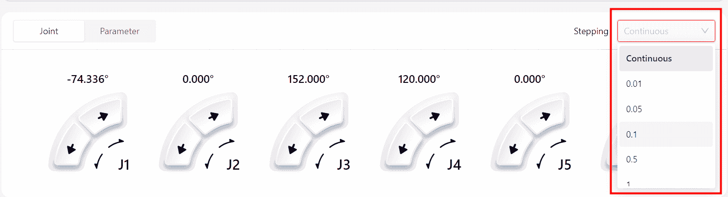
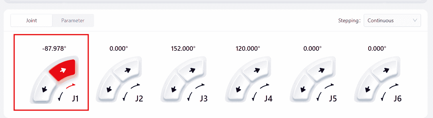
Parameter Adjustment
This allows controlling the robot's movement to a specific position by entering exact values for the Tool Coordinate Position or Joint Position.
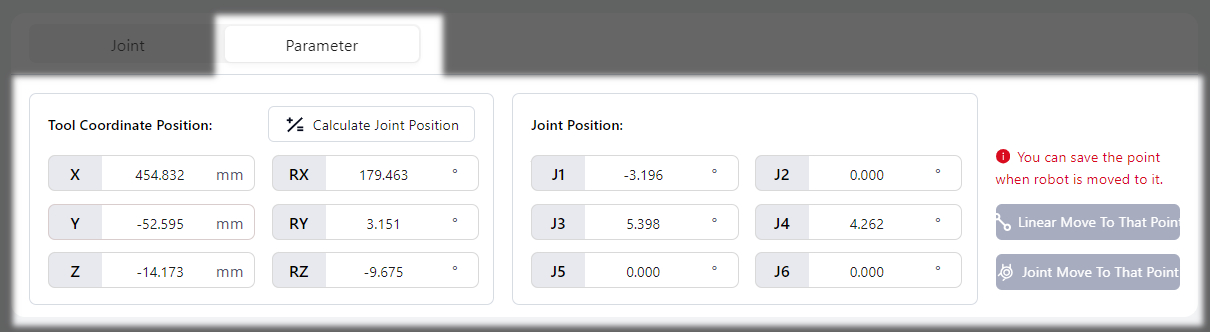
Tool Coordinate Position
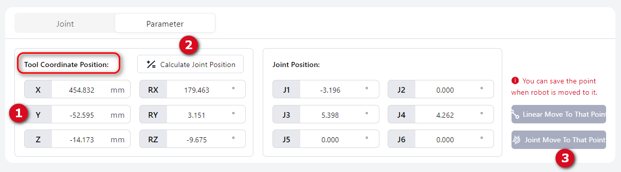
After entering values in the boxes corresponding to different axes, click Calculate Joint Position , then press and hold Linear Move to Point or Joint Move to Point (the button turns red when pressed) to move the robot to the specified position. The robot stops automatically upon reaching the specified position.
Note:
When setting the tool coordinate position, ensure the coordinate system is properly configured.
In the Cartesian-Speed, the robot's movement speed can be adjusted by dragging the slider or directly entering a value (1-100) in the box.
Joint Position
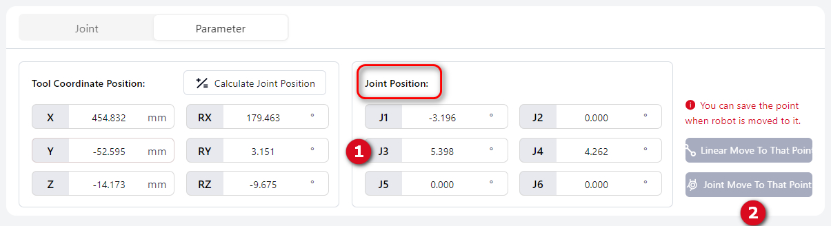
After inputting specific values into the boxes representing different joints, press and hold Move by MoveL or Move by MoveJt (the button turns red when pressed) to move the robot to the designated position. The robot will automatically stop upon reaching the specified position.
The robot's movement speed can be adjusted in Cartesian-Speed . This can be done by dragging the slider or directly entering a specific value (1-100) in the box.
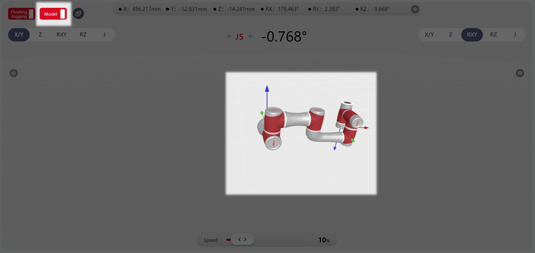
Floating Jogging Area
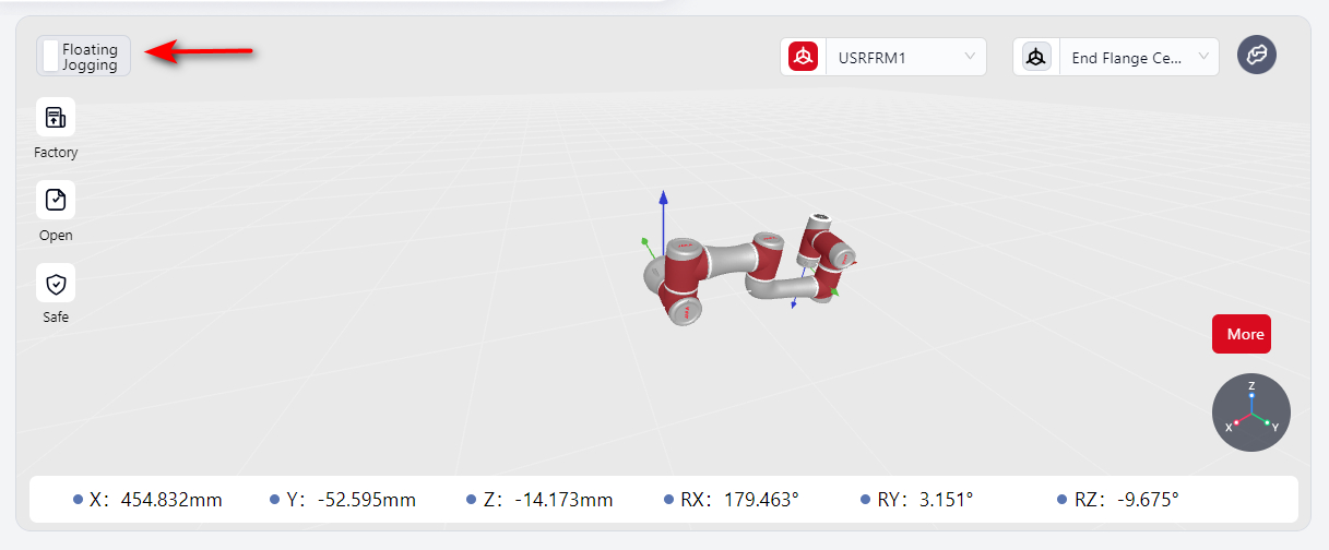
Click Floating Jogging to enter its interface.
Note:
After enabling this function, the world (user) coordinate system and tool coordinate system settings outside this interface remain effective.
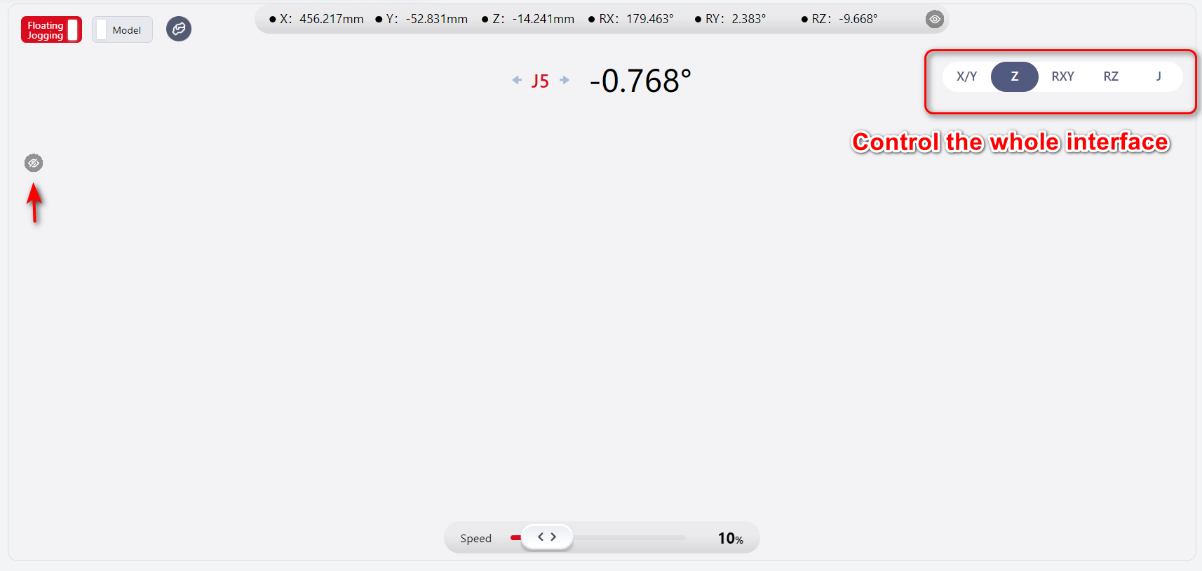
Pose Parameter Display and Speed Adjustment
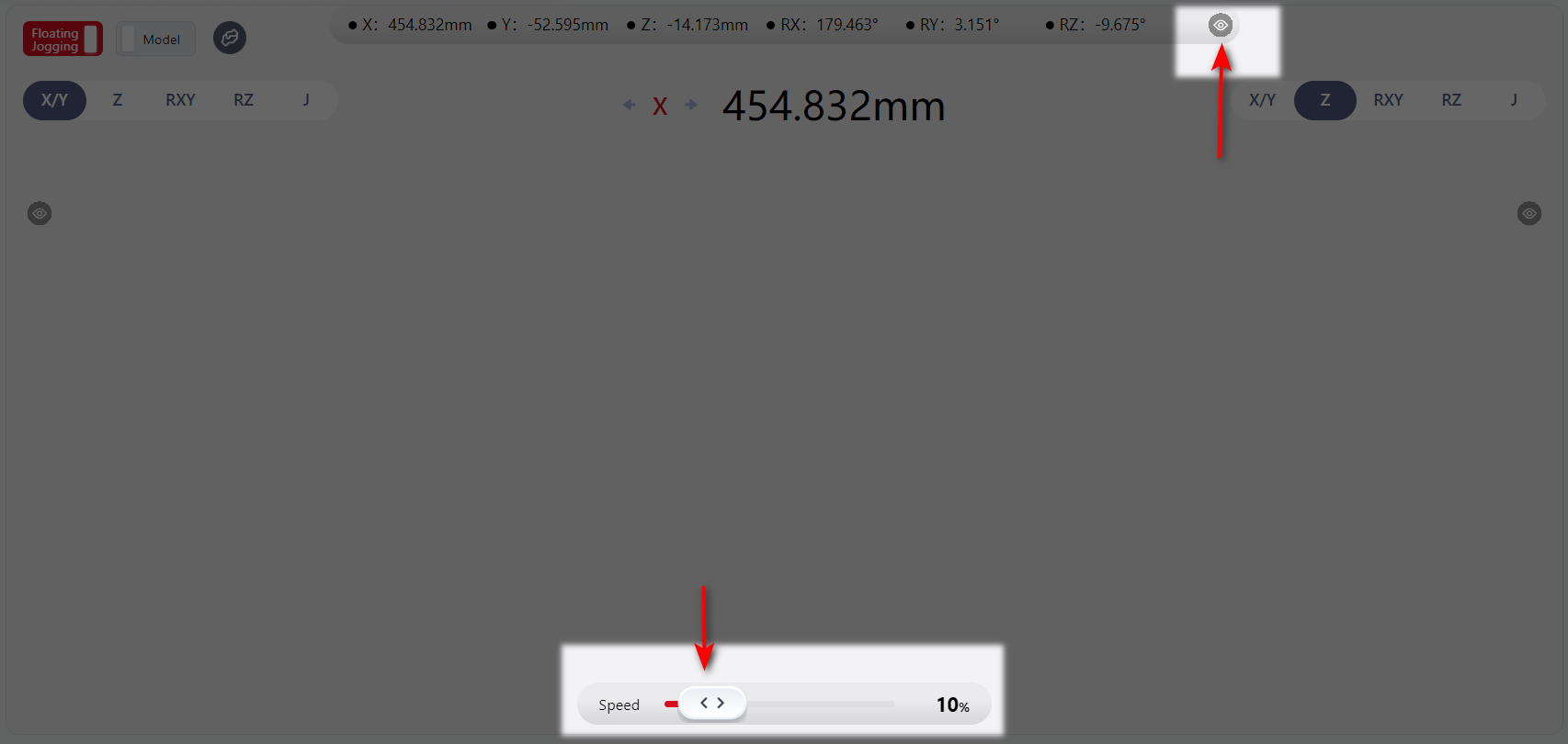
The real-time pose parameters of the robot's movement are displayed at the top of the page. Clicking the eye icon hides the parameter display, and clicking the eye icon again will restore the display.
The speed of the robot's movement can be adjusted by dragging the slider at the bottom of the page.
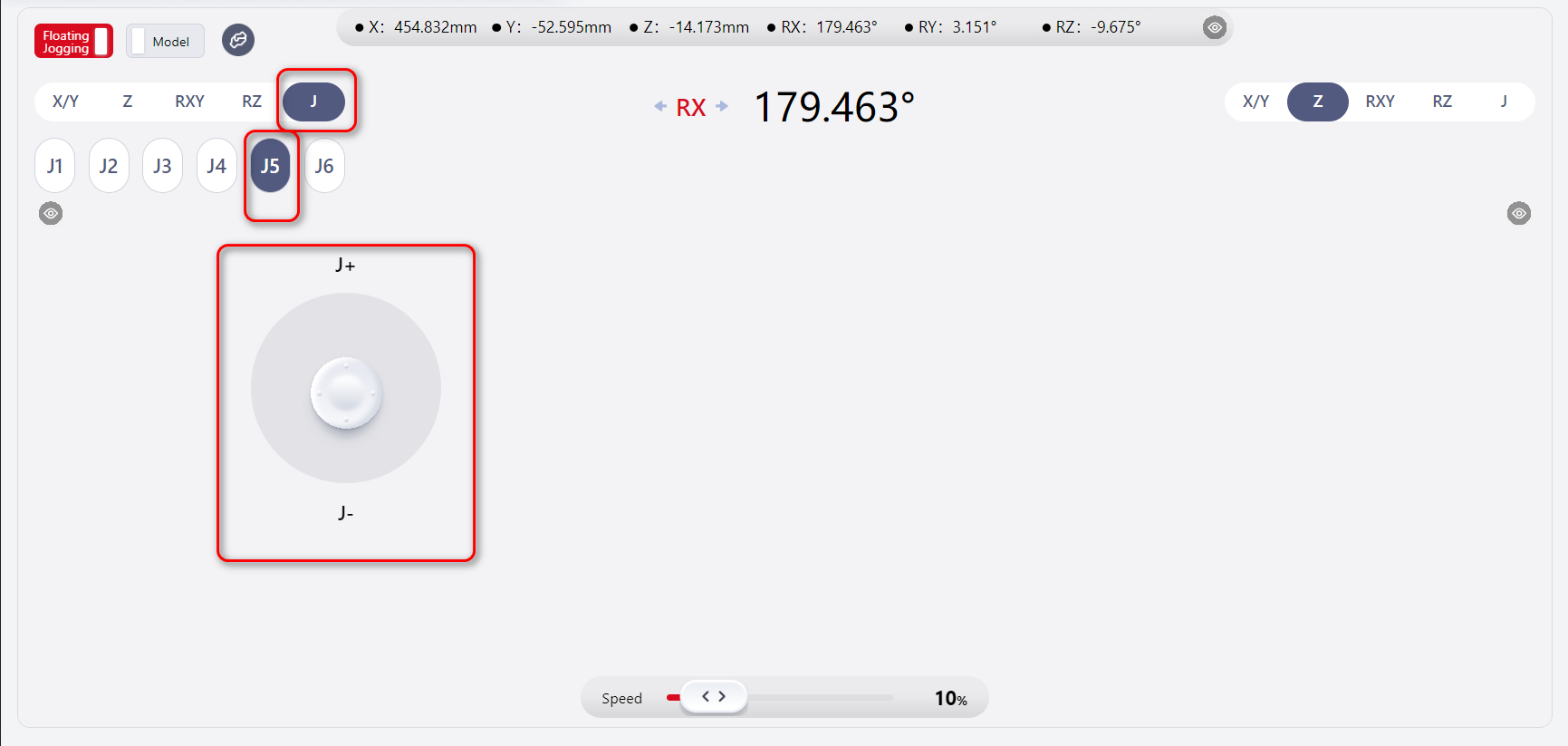
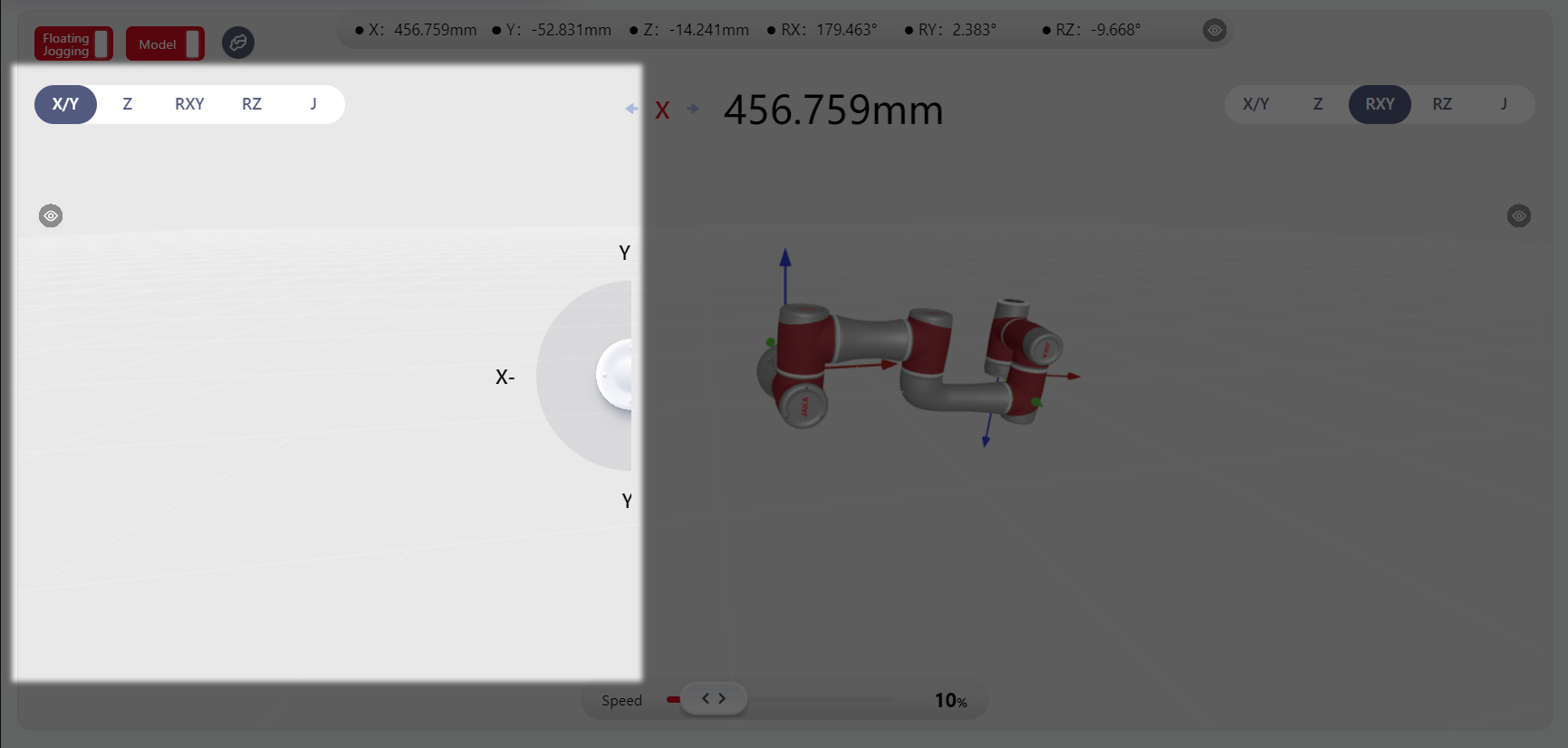
Joystick Control Area
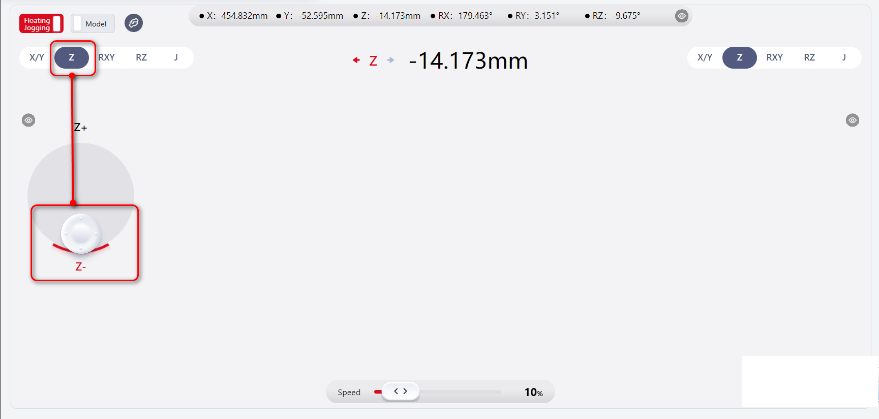
Select an item in the box at the top left of the interface; this operation determines the direction in which the robot will move next.
Click anywhere on the interface to display the joystick.
Press and hold the mouse while moving it in any direction on the joystick to control the robot. The robot will move in the specified direction.
Release the mouse to make the joystick disappear, and the robot will stop moving.
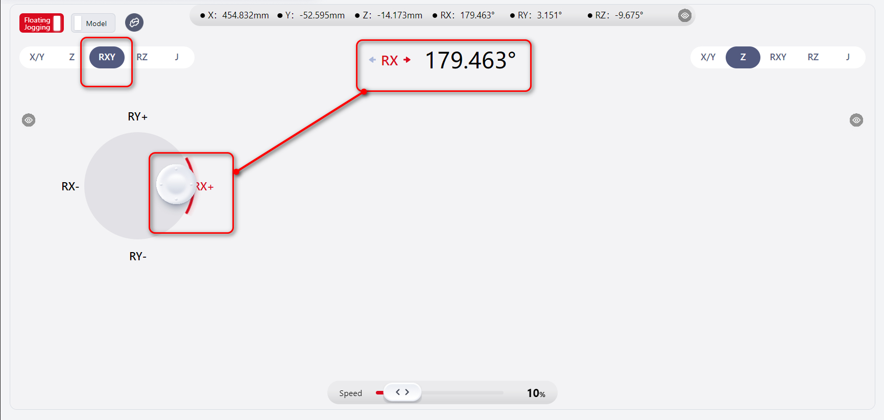
The middle of the interface displays the robot's current movement direction and specific parameters.
The joystick can also be used to control joint movement directly.
As shown, both the left and right areas of the joystick control zone support operation, with the operative range highlighted in the diagram.
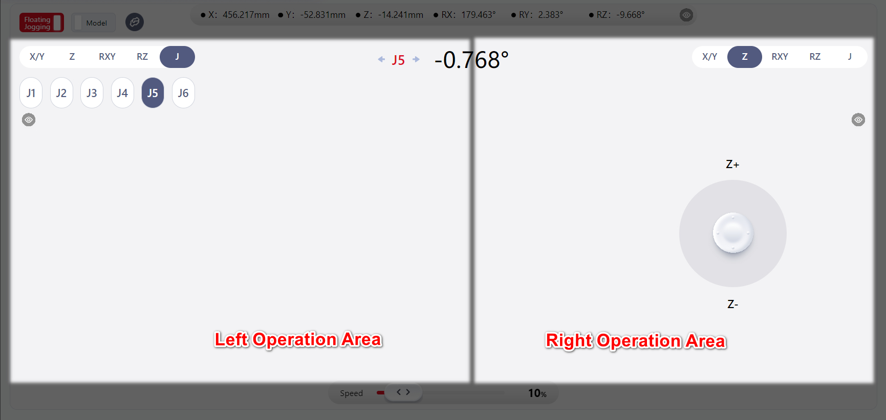
The operation method for the right zone is the same as for the left zone.
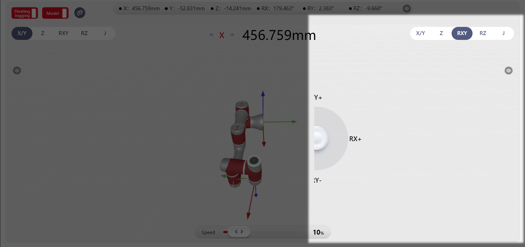
Clicking the eye icon hides the movement direction selection box in the same area.
At this point, the joystick function in that area is also disabled, and the joystick in the other area controls the robot's movement. The effective joystick area then covers the entire page.
As shown above, the movement direction selection box and joystick in the left area are hidden, allowing the right-side joystick to control the entire page.
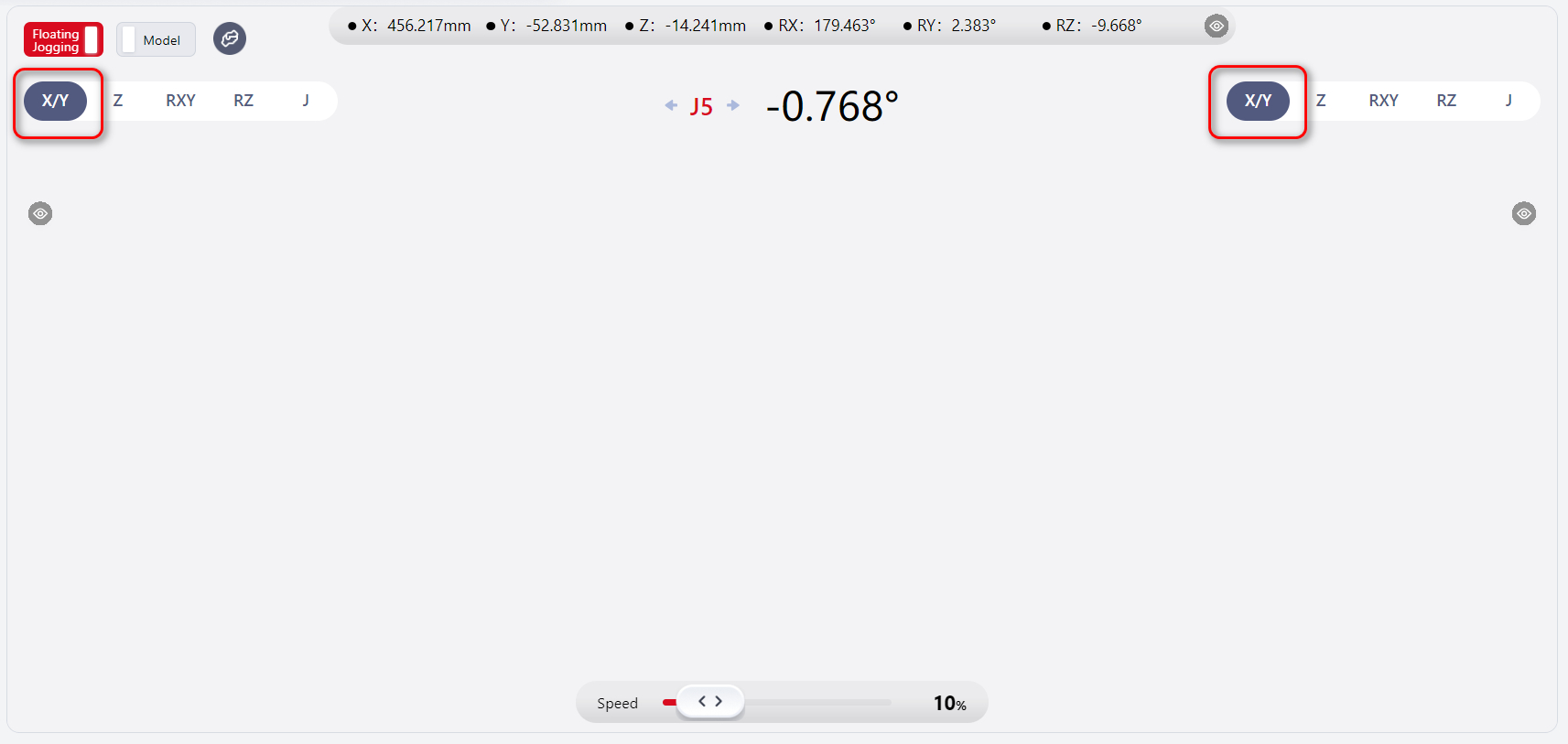
The user can select the same direction in the boxes at the top of both the left and right pages, allowing control of the robot's movement in the selected direction from either the left or right joystick operation area.
As shown above, both the left and right sides have X/Y , so the user can control the robot's movement in the X/Y direction from either the left or right joystick area.
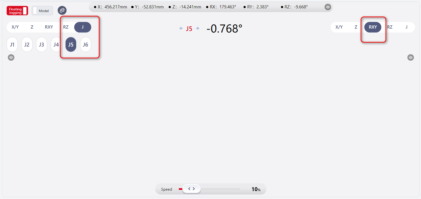
The user can also select different directions.
As shown above, the left side is set to J-J5 , while the right side is set to RXY , so the user can control the robot's third joint movement from the left joystick area and the robot's movement in the RXY direction from the right joystick area.
Note:
The left and right areas cannot be operated simultaneously.
Model Display
Upon entering the Floating Jogging interface, the model is not displayed by default.
Clicking Model in the upper left corner will display the 3D model of the robot in the center of the page. This model corresponds to the actual or virtual robot currently in operation.
Hovering the mouse over any highlighted area near the robot and scrolling the mouse wheel allows zooming in and out, making it easier to observe the robot's full view or details.
Hovering the mouse over any highlighted area near the robot and moving the mouse while holding down the left mouse button allows changing the view direction for a more convenient 360° observation of the robot.
After displaying the model, the operation areas of the joysticks on both sides will be reduced accordingly, as shown below:
Force Control Function
Tips
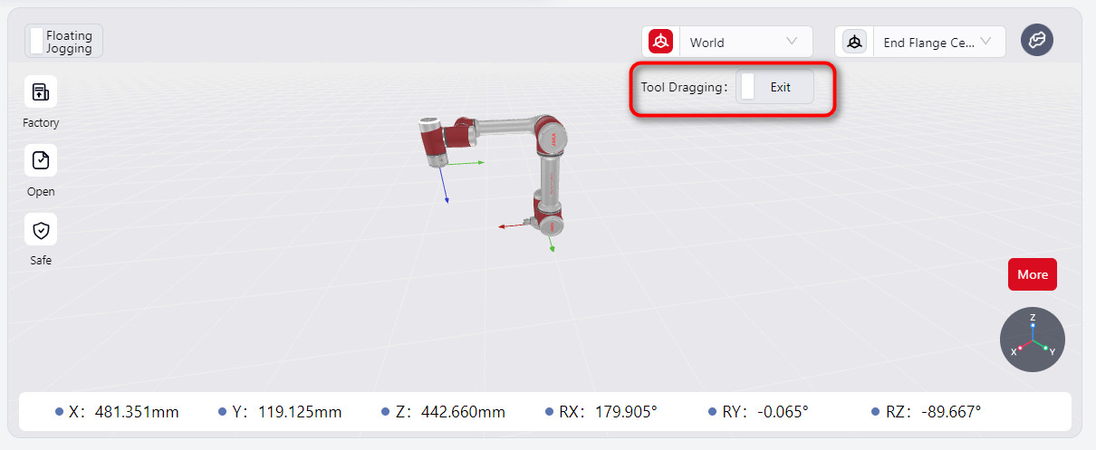
JAKA robots can be used with end sensors for enhanced force control.
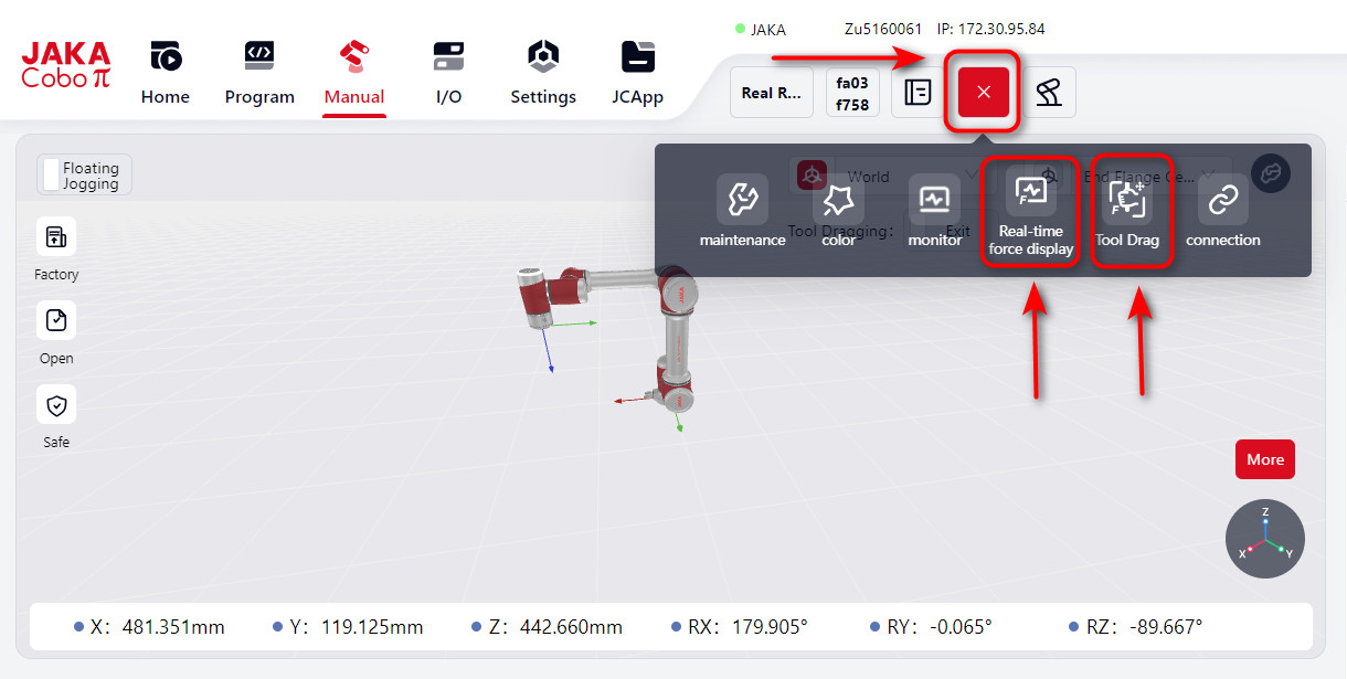
When an end-effector sensor is connected, the Tool Dragging option will appear on the manual control page. Click it to enter the tool dragging mode.
Note:
- Before enabling tool dragging, ensure that the robot's load has been set correctly.
- Before configuring direction, feel, rebound, and other parameters, ensure that tool dragging mode is turned off.
- After enabling tool dragging, the system will check the force values from the sensor. If they exceed 3 N or 0.2 Nm (indicating external force), a popup will prompt you to confirm whether you still want to enable tool dragging. Verify if there is actual external force; if so, click “Confirm” to proceed. If no external force is detected, the sensor's zero point might have shifted. In this case, click "Cancel" to go to the force display window and calibrate the sensor.
Real-time Force Display
You can view the robot's real-time data by selecting Real-time Force Display from the top navigation bar. Clicking it will open a page that shows the current contact force values in real time.
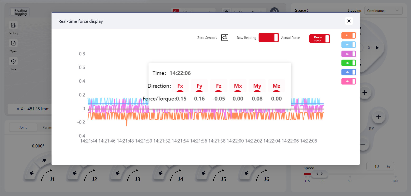
You can toggle the switches for Fx, Fy, Fz, Mx, My, and Mz to display the corresponding force data curves.
When the Real-time toggle is on, the force curve will continuously refresh. When off, the curve will stop refreshing, and it will display the last recorded force curve. Click on any point on the curve to see the recorded force data at that moment.
Tool Dragging
Click on Tool Dragging to enter the configuration interface where you can set various parameters and options:
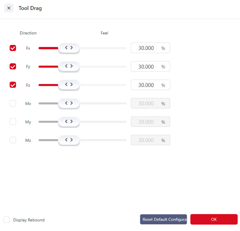
Direction
Fx, Fy, Fz correspond to displacements along the X, Y, and Z axes, while Mx, My, Mz correspond to rotations around the X, Y, and Z axes.
You can select one or more directions, and once tool dragging is enabled, the robot can be dragged along the selected direction(s).
Feel
The feel setting determines the force required to move the robot in Tool Dragging mode. The harder the feel setting, the greater the force needed to drag the robot. Fx, Fy, and Fz correspond to displacements along the X, Y, and Z axes, while Mx, My, and Mz correspond to rotations around these axes. When the checkbox for a specific direction is selected, the feel slider for that direction turns red. Adjust the slider to modify the feel stiffness, and click "Confirm" to enable dragging the robot in that direction.
The default feel setting is 30%.
Rebound
The rebound setting allows the robot to simulate a spring effect: the further the robot moves from its starting point, the greater the force required to drag it, and upon release, the robot will return to its initial position before dragging.
A higher rebound value increases the force needed to drag the robot and the speed at which it rebounds upon release.
Enter a rebound value in the input box and click "Confirm" to activate the rebound function. The default rebound value is 0, and the maximum value is 100.
Select the Show Rebound Values checkbox to display a list of rebound data.
Force Control Coordinate System Selection
Selecting Tool Coordinate System enables dragging the robot within the configured tool coordinate system.
Selecting World Coordinate System enables dragging the robot within the robot's world coordinate system.
Warning:
- After the device is installed, upon restarting the robot, recovering from a fault, or after the sensor has been powered on for an extended period, it is recommended to set the feel stiffness to a harder setting. Test to confirm there are no faults before adjusting to the desired level.
- Adjust the feel setting based on practical needs. Overly soft settings may make the robot too sensitive, potentially leading to excessive speed and acceleration under external forces, which could compromise overall system stability.
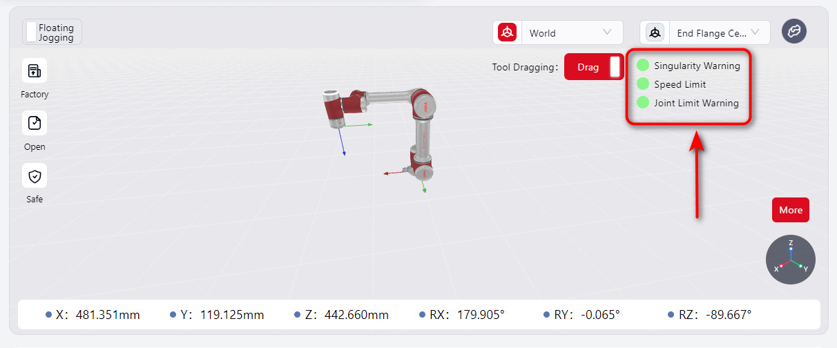
When the S-series robot enters Tool Dragging mode, the Tool Dragging switch on the manual operation interface is activated, displaying singularity warnings, speed limits, and joint soft limit status indicators.
When a limit is triggered, the indicator light on the manual operation interface turns red, and a red halo appears around the affected joint.
As the robot approaches a singularity or joint soft limit, the dragging feel becomes progressively harder. However, moving away from the limit will not be affected. Meanwhile, the robot’s end ring indicator flashes red and yellow.
The singularity warning range for dragging can be set in the Force Control Configuration - Advanced Feature Configurationinterface. Refer to the JAKA S-Series Hardware User Manual for singularity positions.
When the TCP dragging speed at the robot’s end reaches the limit, it will be capped, preventing further acceleration. The robot's end ring indicator will flash red and yellow.
The force control speed limit can be set in the Force Control Configuration - Advanced Feature Configuration interface.
Warning:
Avoid enabling Tool Dragging in postures that are very close to singularities or joint limits, as these postures may exceed the allowable range for Tool Dragging. Due to safety restrictions, the robot cannot be dragged even if Tool Dragging is enabled.
In such cases, move away from singularities or joint limit postures using joint motion before enabling Tool Dragging.