I/O Panel
I/O Panel
The I/O panel allows users to view and configure the electrical I/O of the robot control cabinet.
Note:
When setting up the I/O, the robot must be in a disabled status.
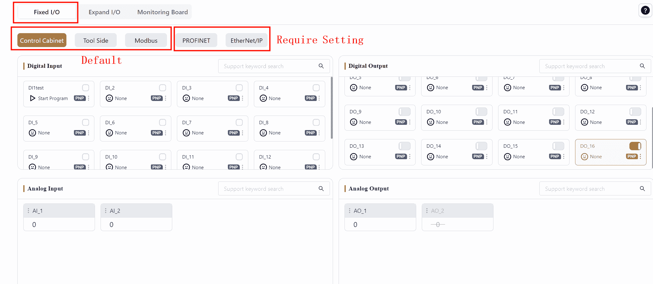
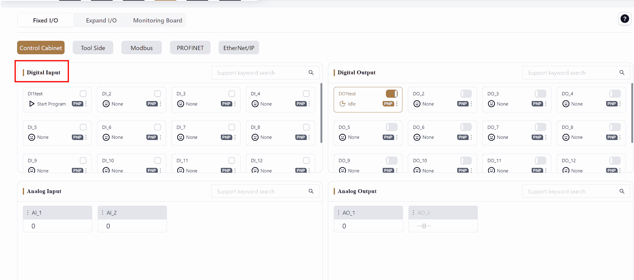
Fixed I/O
There are five types of Fixed I/O. Control Cabinet I/O, Tool-end I/O, and Modbus I/O are the default I/O types.
PROFINET I/O and Ethernet I/O will only appear here after being enabled in the Settings.
DI/DO Signal Card Explanation:
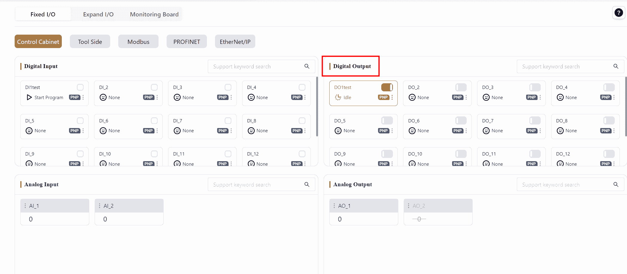
In the I/O panel, the DI/DO signal card format is consistent across Fixed I/O, Dynamic I/O, and Monitor Board. The DI/DO signal card structure is explained here.
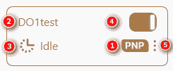
1 Indicates the user DI/DO type for the control cabinet, including PNP and NPN types. Currently, JAKA’s standard cabinets are PNP type, while MiniCab cabinets are NPN type.
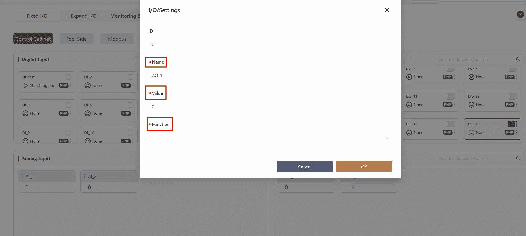
2 Indicates the DI/DO name, which can be edited by the user.
3 Indicates the DI/DO function, which can be selected by the user.
4 Indicates the DI/DO status.
5 Clicking this symbol or any blank area on the card opens the Settings page, where the DI/DO name and function can be configured.
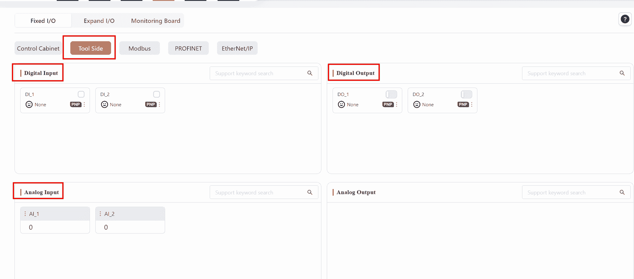
Control Cabinet
The control cabinet is divided into two types: the standard cabinet CAB 2.1 and the MiniCab:
CAB 2.1: It features 16 physical inputs, 16 physical outputs, and 2 analog signals, all of which are PNP type, triggered by 24V input. When connecting CAB 2.1 with Coboπ, the I/O panel displays the physical signals from the control cabinet, and the scroll bar on the right can be used to view other I/O statuses.
MiniCab: It features 7 physical digital signals, which are NPN type, triggered by 0V input. When connecting MiniCab with Coboπ, the I/O panel displays the physical signals in the control cabinet. Only one interface type can be selected at a time for a single channel; for instance, if a channel is set as DI, it cannot be simultaneously set as DO.
Digital Input(DI)
Warning:
This DI section is identical for both the standard cabinet and MiniCab.
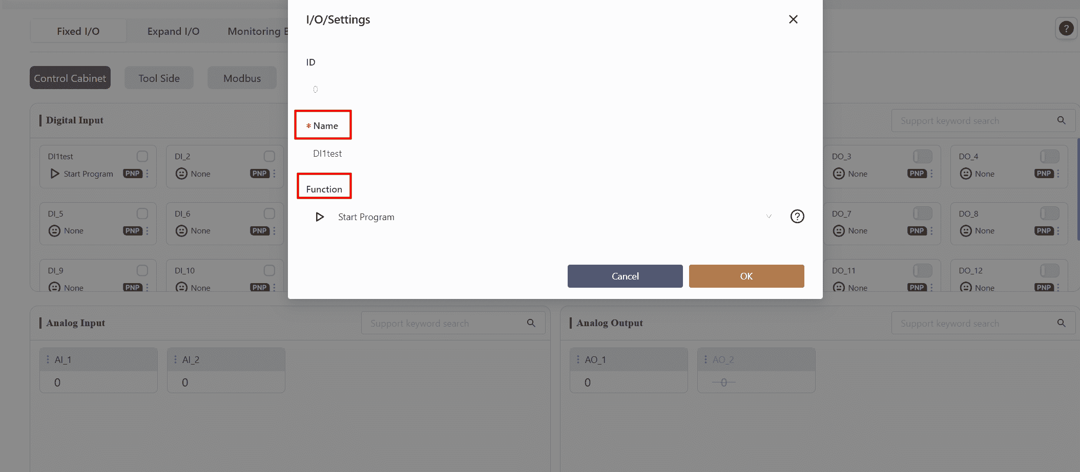
Follow the steps to configure the DI settings. When the DI signal is triggered, the corresponding function will be activated.
The supported functions for DI signals are listed in the table below:
| Icon | Function Name | Function Description | Trigger Method |
|---|---|---|---|
 | None | None | None |
 | Start Program | When the Start Program DI is triggered, the robot executes the currently open program in the programming control interface. This DI is typically used to resume a stopped program. Note: Ensure the program in the programming interface is saved before triggering this DI. If there is an unsaved program, the robot will execute the last saved program when this DI is triggered. | Rising edge signal |
 | Pause Program | When the Pause Program DI is triggered, the robot pauses the currently open program in the programming control interface. The program can be resumed by triggering the Continue Program DI. | Rising edge signal |
 | Continue Program | When the Continue Program DI is triggered, the robot resumes executing the currently open program in the programming control interface. This DI is typically used to resume a paused program. | Rising edge signal |
 | Stop Program | When the Stop Program DI is triggered, the robot stops the currently open program in the programming control interface. The program can be resumed by triggering the Start Program DI. | Rising edge signal |
 | Power On | When the Power On DI is triggered, the robot powers on. | Rising edge signal |
 | Power Off | When the Power Off DI is triggered, the robot powers off. | Rising edge signal |
 | Enable Robot | When the Enable Robot DI is triggered, the robot is enabled. | Rising edge signal |
 | Disable Robot | When the Disable Robot DI is triggered, the robot is disabled. | Rising edge signal |
 | Speed Reduction Mode 1 | When the Speed Reduction Mode 1 DI is triggered, the robot slows down and enters the first level of speed reduction mode. | Low-level signal |
 | Protective Stop | When the Protective Stop DI is triggered, the robot's movement stops. | Low-level signal |
 | Return to Initial Position | When the Return to Initial Position DI is triggered, the robot moves to the safe posture position set in the Settings - Safety Settings - Robot Orientation interface. | Rising edge signal |
 | Speed Reduction Mode 2 | When the Speed Reduction Mode 2 DI is triggered, the robot slows down and enters the second level of speed reduction mode. | Low-level signal |
 | Clear Collision | When the Clear Collision DI is triggered, the robot's collision alarm is cleared. | Rising edge signal |
 | Enter Drag Mode | When the Enter Drag Mode DI is triggered, the robot enters drag mode. | Rising edge signal |
 | Exit Drag Mode | When the Exit Drag Mode DI is triggered, the robot exits drag mode. | Rising edge signal |
Note:
- The second-level speed should be lower than the first-level speed.
- The I/O functions are triggered by edge signals (rising or falling edges). To avoid delays caused by network communication fluctuations affecting the triggering of function I/Os, it is recommended that the signal level be maintained for at least 500 ms before and after the edge signal.
Digital Output(DO)
Warning:
This DO section is identical for both the standard cabinet and MiniCab.
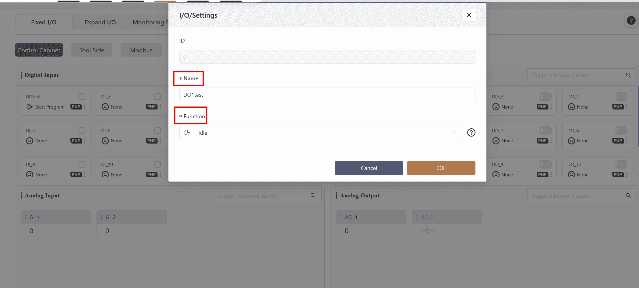
Follow the steps to configure the functions bound to the DO. After confirming, the DO signal will reflect the status of the bound system state in real-time.
The supported system statuses for binding to DO signals are listed in the table below:
| Icon | Robot Status | Function Description | Signal Status |
|---|---|---|---|
| None | None | None |
 | Idle | Idle indicates that the robot is not running any program. | High-level signal |
| Program Paused | Program Paused indicates that the currently open program in the programming control interface is paused. | High-level signal |
| Program Running | Program Running indicates that the robot is executing the currently open program in the programming control interface. | High-level signal |
 | Error | Error indicates that the robot has triggered a collision alarm. | High-level signal |
 | Powered On | Powered On indicates that the robot is in a powered-on state. | High-level signal |
| Enabled | Enabled indicates that the robot is in an enabled state. | High-level signal |
 | In Motion | In Motion indicates that the robot is moving (e.g., executing a program, manual control, secondary development control, freedrive mode and etc.). | High-level signal |
 | Stationary | Stationary indicates that the robot is in a stationary state (e.g., program paused, not running any program, program ended, waiting for a signal, etc.). | High-level signal |
| Powered On | Powered On indicates that the control cabinet is in a powered-on state. | High-level signal |
 | Emergency Stop | Emergency Stop indicates that the robot's movement has stopped, and it is in a powered-off and disabled state. | High-level signal |
| Speed Reduction Mode 1 | Speed Reduction Mode 1 indicates that the robot is in the first level of speed reduction mode. | High-level signal |
| Speed Reduction Mode 2 | Speed Reduction Mode 2 indicates that the robot is in the second level of speed reduction mode. | High-level signal |
| Protective Stop | Protective Stop indicates that the robot's movement has stopped. | High-level signal |
 | Initial Position | Initial Position is the user-defined safe posture position set in the Settings - Safety Settings - Robot Orientation interface. When the robot is in this position, this signal is triggered. | High-level signal |
| Drag Mode | Drag Mode indicates that the robot is in drag mode. | High-level signal |
 | Collision | Collision indicates that the robot has collided. | High-level signal |
Analog Input(AI)
Warning:
This feature is only supported by the standard cabinet.
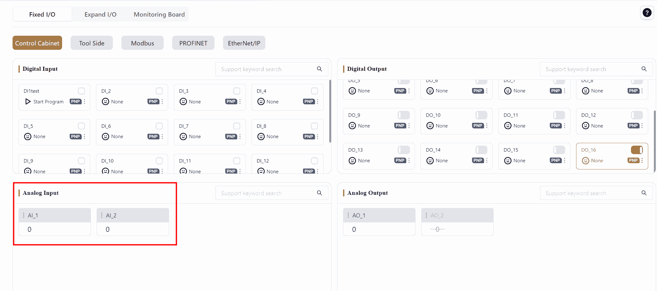
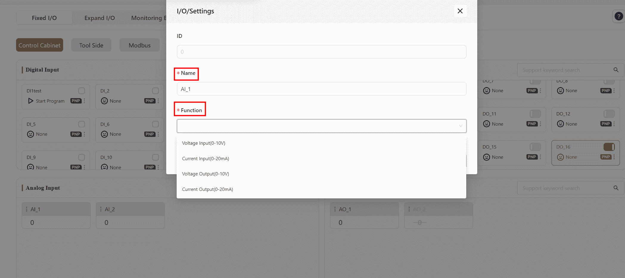
The analog input interface allows for monitoring analog signals. The operation method is the same as described for DI/DO above.
Analog Output(AO)
Warning:
This feature is only supported by the standard cabinet.
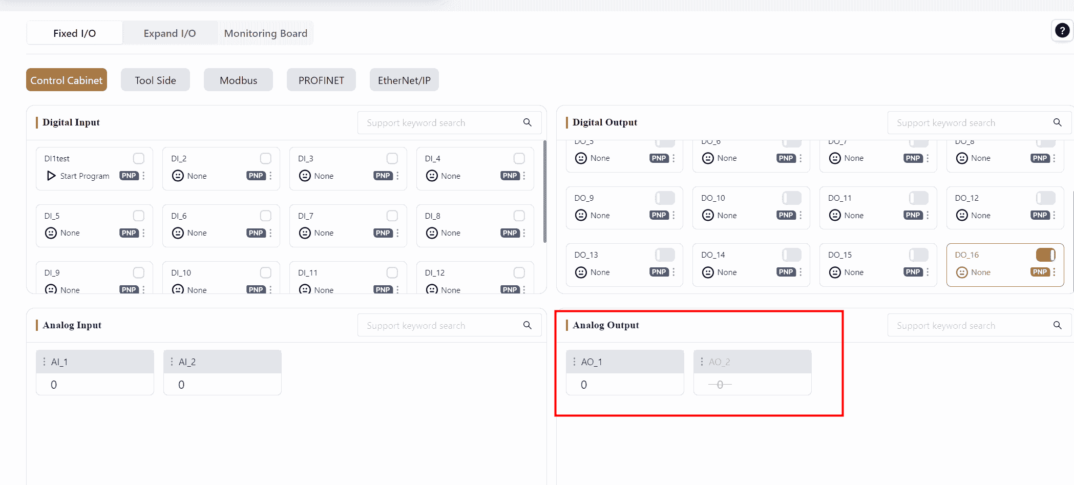
The analog output interface allows for monitoring analog signals. The operation method is the same as described for DI/DO above.
TIO
The robot's end effector TIO (Tool I/O) has two versions, V2 and V3. This section explains V3. For instructions on other versions, please contact JAKA technical support.
When using the end effector TIO, configurations can be made via Settings - Hardware and Communications - Tool I/O or directly from this interface.
The V3 version tool interface on the robot body supports 2 channels of digital input, 2 channels of digital output, and 2 channels of analog input. The 2 digital outputs can be repurposed as a high-speed RS485 channel, and the 2 analog inputs can be repurposed as a low-speed RS485 channel.
Digital Input
The TIO function supports 2 DI channels that can be individually set to different input modes, either NPN type input or PNP type input. Upon powering the TIO, both DI channels are configured to NPN input by default.
The setup method is the same as in the control cabinet.
Digital Output
The TIO function allows the 2 DO channels to be repurposed as RS485 channel pins. When used as DO, each channel can be set to different output modes, such as NPN output, PNP output, or push-pull output. Upon powering the TIO, both DO channels are configured to NPN output by default.
The setup method is the same as in the control cabinet.
Warning:
When using the 2 DO channels as an RS485 channel, both channels must be set to RS485 Channel 1 mode.
When one DO is switched to RS485 Channel 1 mode, the other will also be set to RS485 Channel 1. If one DO is switched from RS485 Channel 1 mode to another mode, the other DO will automatically be set to NPN output mode.
Analog Input
The TIO function provides two analog input channels that can be repurposed as RS485 Channel 2.
The setup method is the same as in the control cabinet.
Upon powering the TIO, the analog inputs are used by default.
The voltage range for analog signals is 0-10V, corresponding to a display range of 0-4096. The mapping is 0V corresponding to 0 and 10V corresponding to 4096, with an accuracy of 0.1V.
Note:
Regardless of whether external equipment is connected to the TIO, the AI display value will not be zero. When no external equipment is connected, the displayed value varies depending on the TIO board model, typically around 400-500 or 700-800.
Modbus
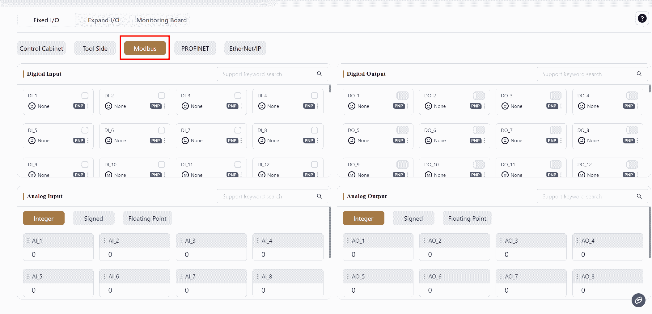
The JAKA robot control cabinet supports the Modbus communication protocol and can function as a Modbus slave to communicate with external devices.
The I/O signals in the Modbus window represent the I/O data accessible via Modbus communication between the robot and external devices. The controller, as a Modbus device, supports 128 digital inputs and 128 digital outputs, 16 integer analog inputs and 16 integer analog outputs, 16 signed analog inputs and 16 signed analog outputs, and 32 floating-point analog inputs and 32 floating-point analog outputs.
For detailed definitions of Modbus register addresses, refer to the:Modbus I/O Address Table For PLC communication configuration, please refer the JAKA Communication User Manual
Digital Input (DI) / Output (DO)
The digital input/output interface allows monitoring of digital input status in Modbus.
DI: When a DI signal is triggered, the selected function is activated.
DO: The DO interface displays the real-time status of the selected function.
The supported functions and detailed descriptions, as well as setup methods, are the same as those for the Control Cabinet.
Analog Input (AI) / Output (AO)
The analog input/output interface allows monitoring of Modbus analog signals.
Modbus values are single-precision floating-point numbers, rounded to seven significant digits. Values exceeding the significant digits will be rounded.
The setup method is the same as above.
PROFINET
Note:
Both PROFINET and EtherNet/IP need to be enabled in Settings - Hardware and Communications - PROFINET Settings and EtherNet/IP Settings before they will appear on the I/O Panel.
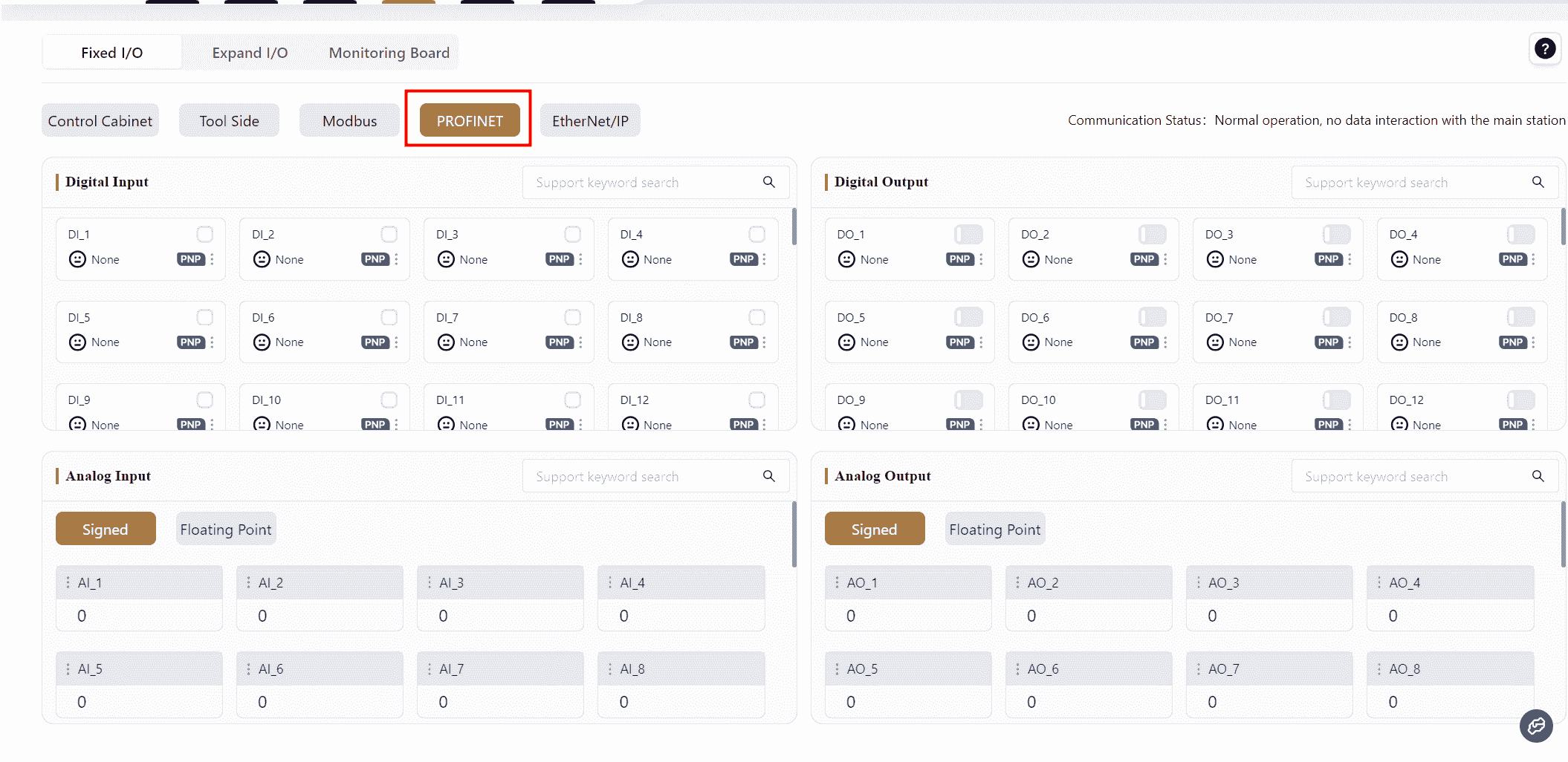
The control cabinet supports the PROFINET communication protocol and can act as a PROFINET I/O slave, facilitating communication with external devices.
In the PROFINET window, the I/O signals represent the I/O data accessible via PROFINET communication between the robot and external devices. As a PROFINET device, the controller supports 64 digital inputs and 64 digital outputs, 32 signed analog inputs, and 32 signed analog outputs, as well as 32 floating-point analog inputs and 32 floating-point analog outputs.
For PROFINET register address definitions, refer to the PROFINET I/O Address table.
To obtain the GSDML–XML device description file, please contact JAKA for technical support.
For PLC communication configuration, refer to JAKA Communication User Manual
The configuration methods for PROFINET digital inputs, digital outputs, analog inputs, and analog outputs are the same as for Modbus.
EtherNet/IP
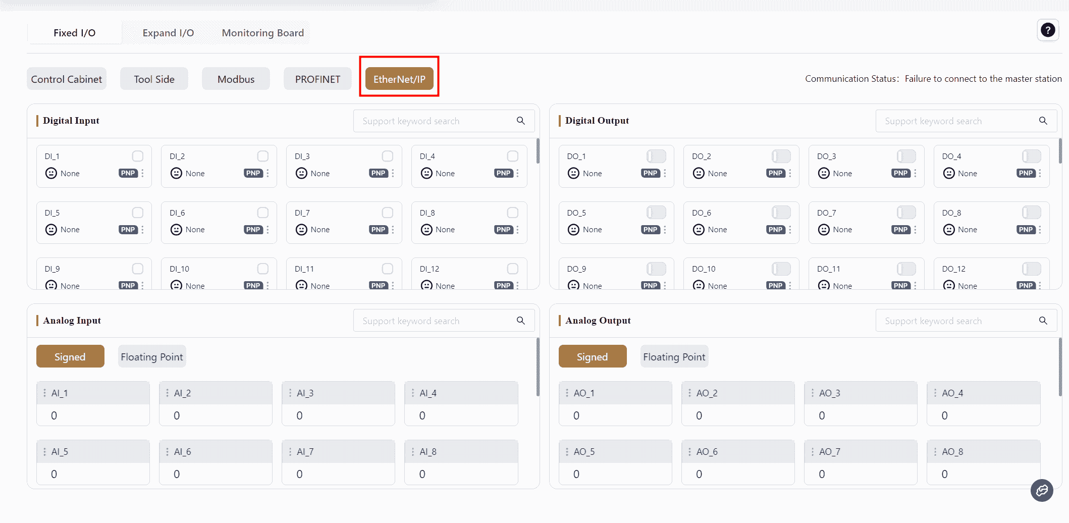
The control cabinet supports the EtherNet/IP communication protocol and can function as an EtherNet/IP “adapter” for communication with external devices.
In the EtherNet/IP window, the I/O signals represent the I/O data accessible via EtherNet/IP communication between the robot and external devices. As an EtherNet/IP device, the controller supports 64 digital inputs and 64 digital outputs, 24 signed analog inputs, and 24 signed analog outputs, as well as 24 floating-point analog inputs and 24 floating-point analog outputs.
For EtherNet/IP register address definitions, refer to Appendix 6: EtherNet/IP I/O Address Table.
To obtain the EDS device description file, please contact JAKA for technical support.
The configuration methods for EtherNet/IP digital inputs, digital outputs, analog inputs, and analog outputs are the same as for Modbus.
Extended I/O
The Extended I/O supports Modbus TCP/IP and Modbus RTU communication protocols, with the robot acting as the Master.
Before configuring the Extended I/O, wiring must be completed:
- For Modbus TCP/IP, connect the standard cabinet to the bottom network port of the control cabinet, or connect the MiniCab to the LAN2 port.
- For Modbus RTU, connect the standard cabinet to the front panel RS485 interface, or connect the MiniCab to the front panel PIN17 and PIN18 I/O interfaces.
For the interface location and wiring methods, refer to the hardware user manual.
Note:
The configuration methods for digital inputs, digital outputs, analog inputs, and analog outputs on the Extended I/O are the same as for Modbus.
The maximum limits for Extended I/O modules are:
- 8 Extended I/O modules
- 32 AI/AO channels
- 64 DI/DO channels
Warning:
When configuring the Expansion I/O, ensure the robot is powered off.
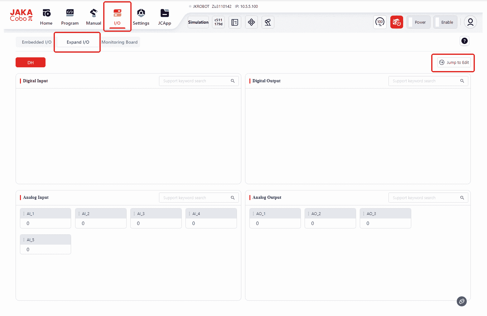
In the initial state without any configured Extended I/O, opening the Extended I/O page will display the same interface as the pages above. At this point, the user needs to click the Jump to Edit button in the top right corner, which will automatically redirect to Settings - Modbus Settings - Slave Station Management.
Then click Add to enter the configuration interface:
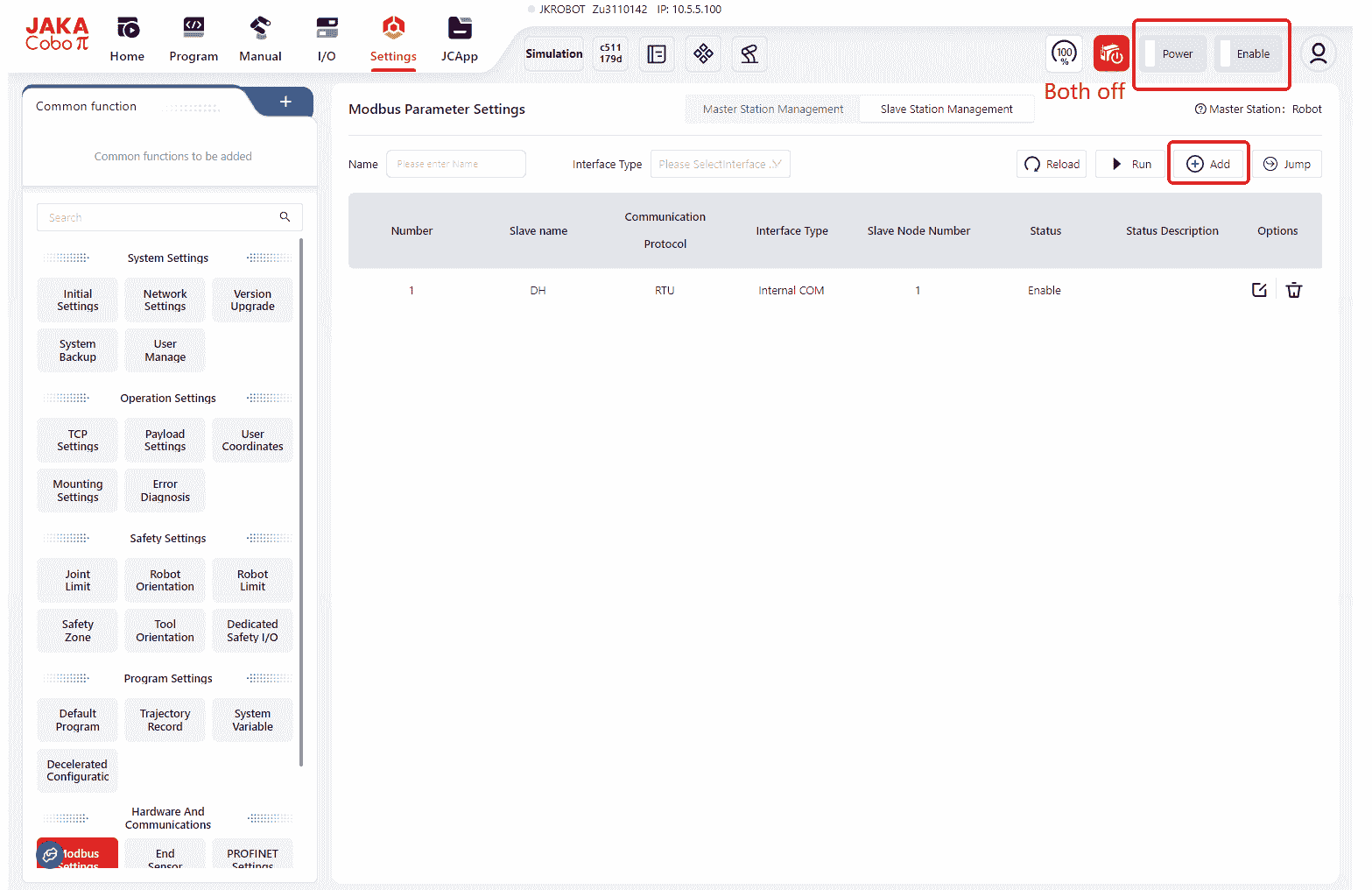
Note:
If the Add button is not visible in the configuration interface as shown below, click Stop first: 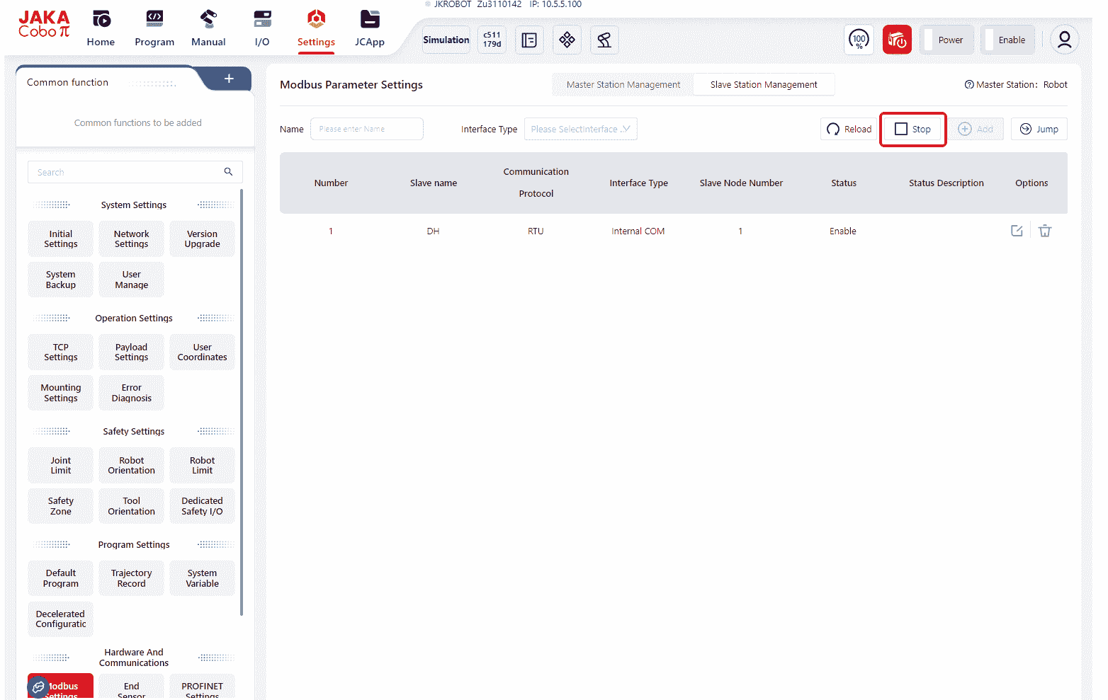
Modbus TCP/IP
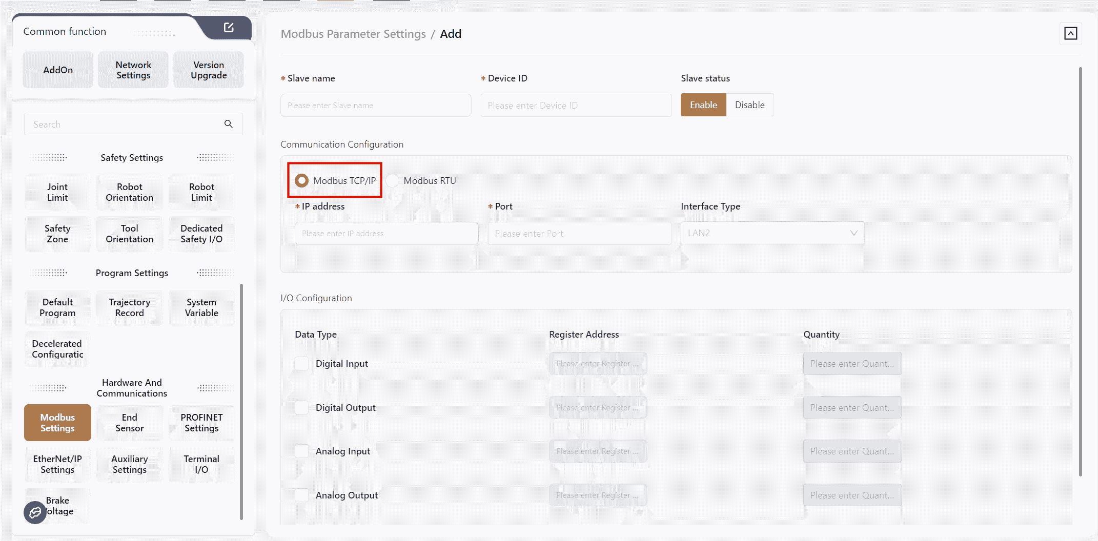
Slave Name:User-defined; ensure it does not duplicate other module names.Device ID:The device number of the slave.IP Address:The IP address of the Modbus TCP/IP slave.Port:The port number of the slave.I/O Configuration: Configure the register addresses and quantities for DI, DO, AI, and AO of the Modbus TCP/IP.
After configuration, click OK,and the newly configured Modbus module will be displayed on the Extended I/O page.
Modbus RTU
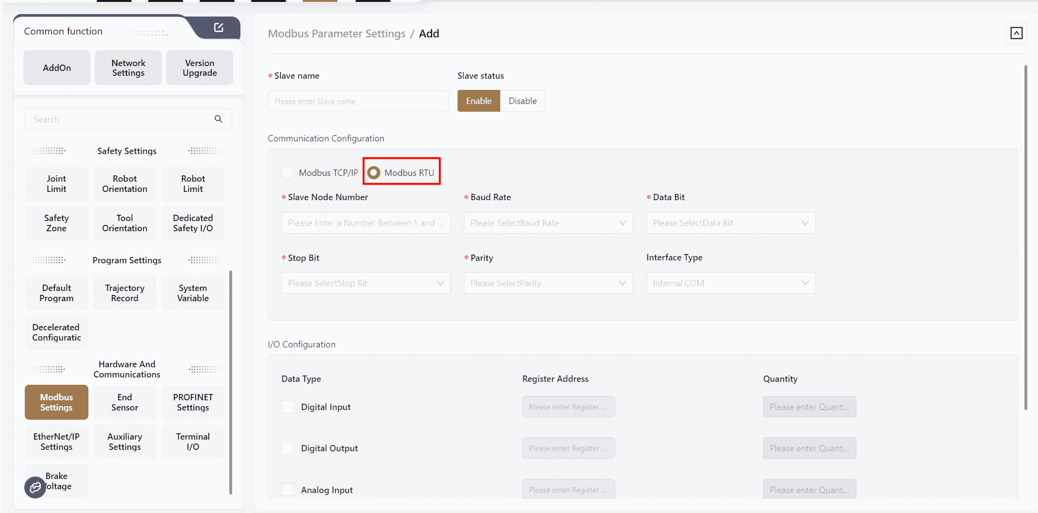
Slave Name:User-defined; ensure it does not duplicate other module names.Slave Node Number:The station number of the configured Modbus RTU.Baud Rate:Select the baud rate for the configured Modbus RTU.Data Bit:Select the data bit length for the configured Modbus RTU.Stop Bit:Select the stop bit length for the configured Modbus RTU.Parity:Select the parity method for the configured Modbus RTU.I/O Configurations: Fill in the register addresses and quantities for DI, DO, AI, and AO according to the Modbus RTU parameters.
After configuration, click OK,and the newly configured Modbus module will be displayed on the Extended I/O page.
Note:
If multiple Modbus RTU extended modules are configured, ensure that bus parameters such as baud rate, stop bit length, data bit length, and parity method are consistent.
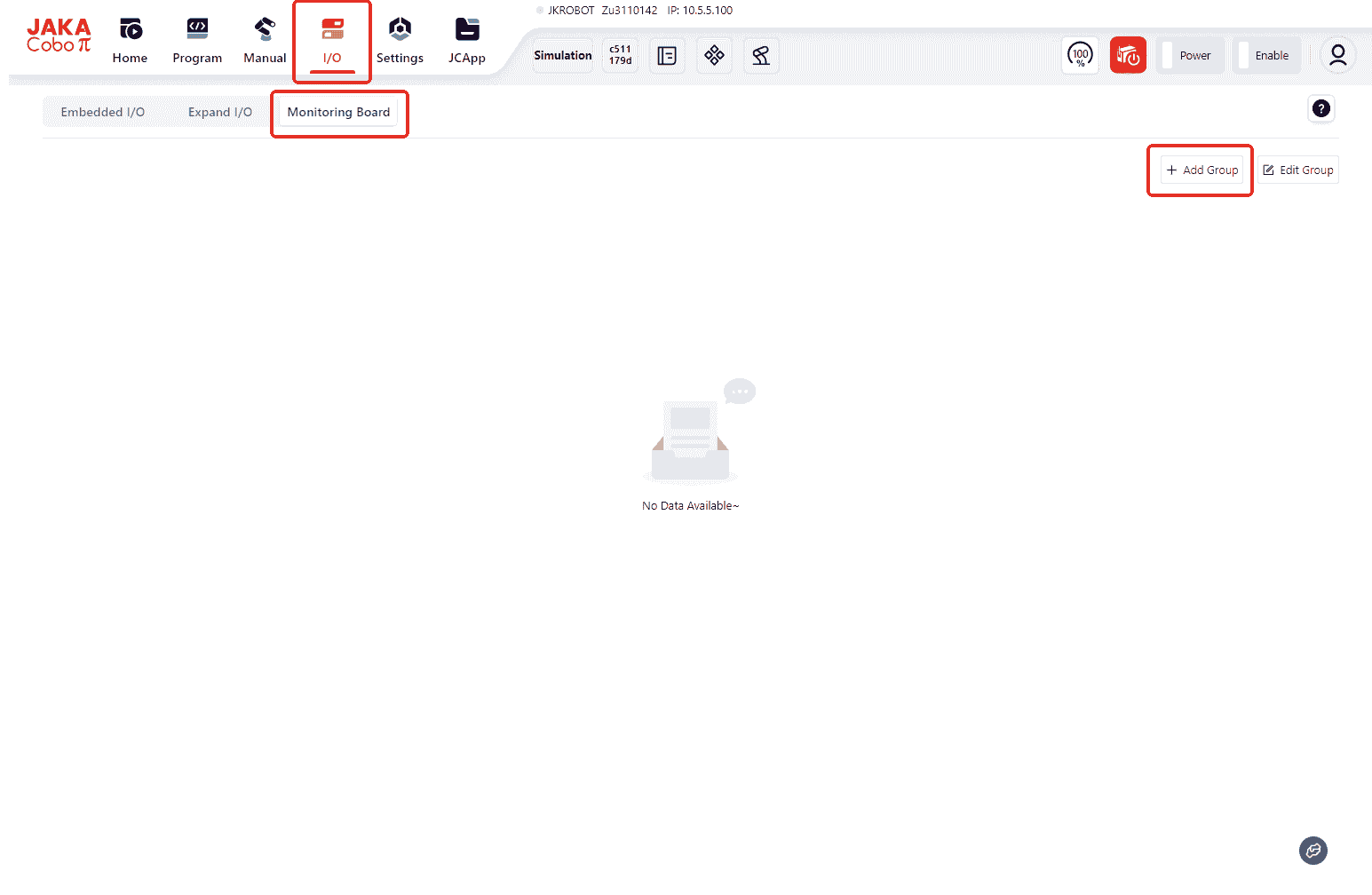
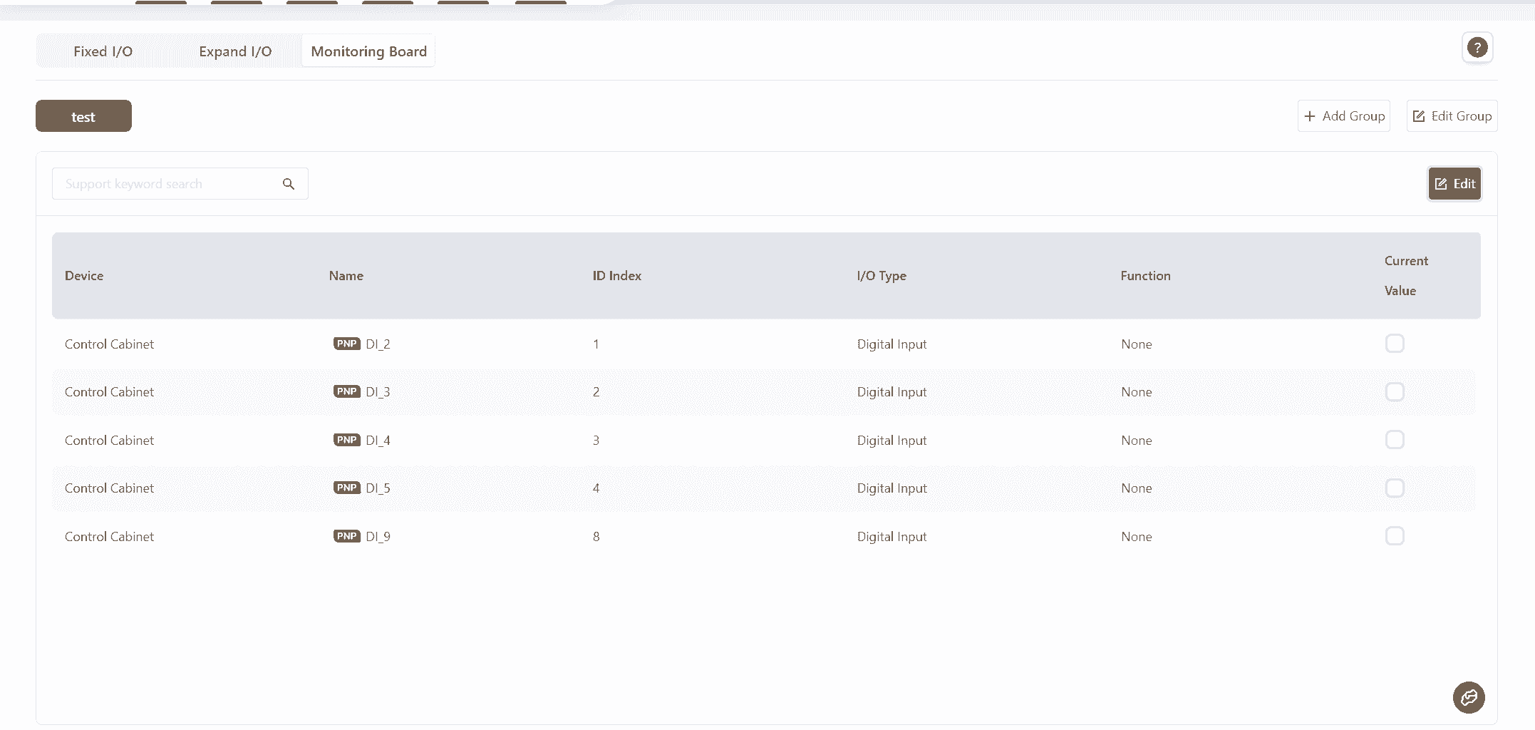
Monitoring Board
Users can add existing fixed I/O and extended I/O to the Monitoring Board page, allowing for centralized viewing during program execution.
The specific steps are as follows:
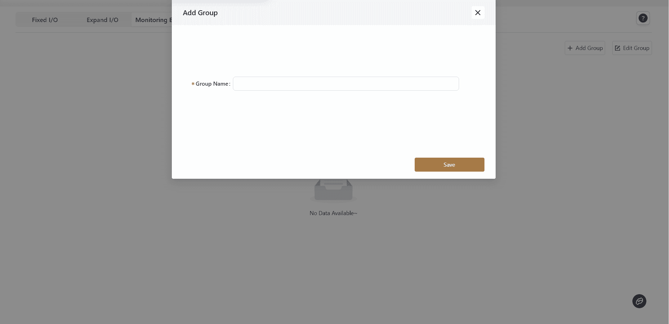
- In the initial state, when no I/O has been added, the
Monitoring Boardpage will appear as shown below. At this point, the user needs to clickAdd Groupin the upper right corner of the page.
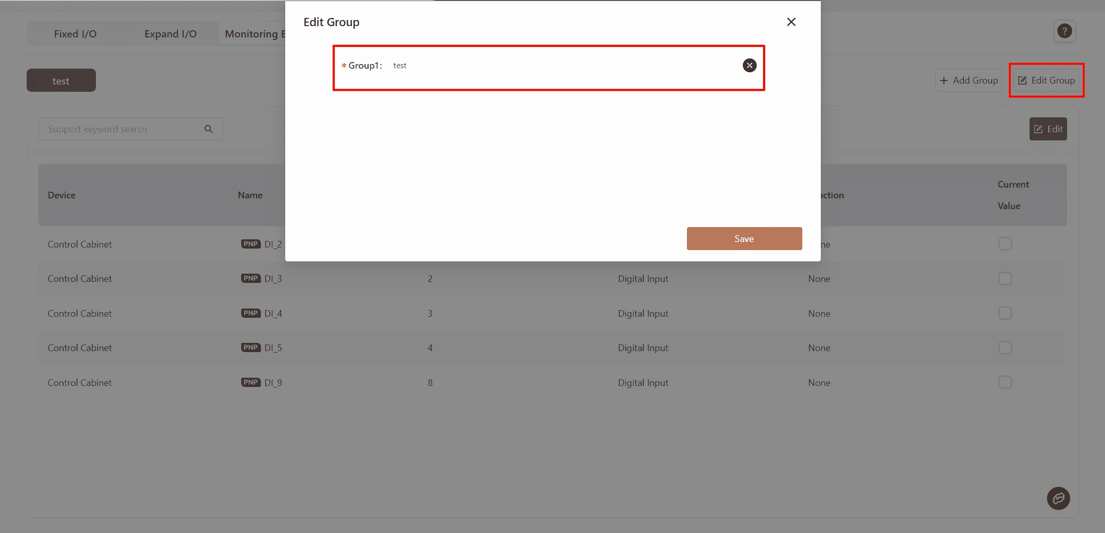
- Enter a custom name in the
Group Namefield and clickSave.
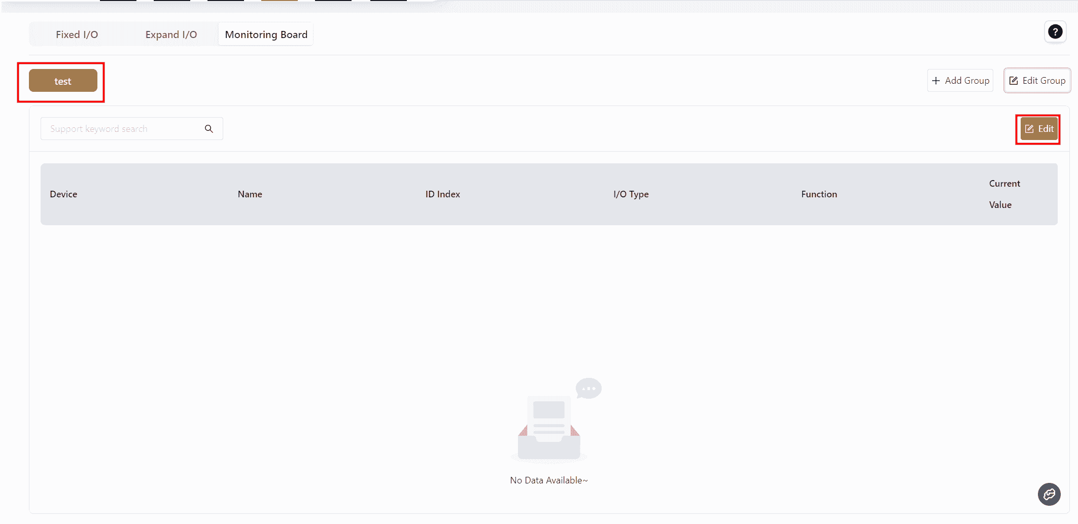
- The saved group will be displayed in the upper left corner of the page. Then, click
Editon the right.
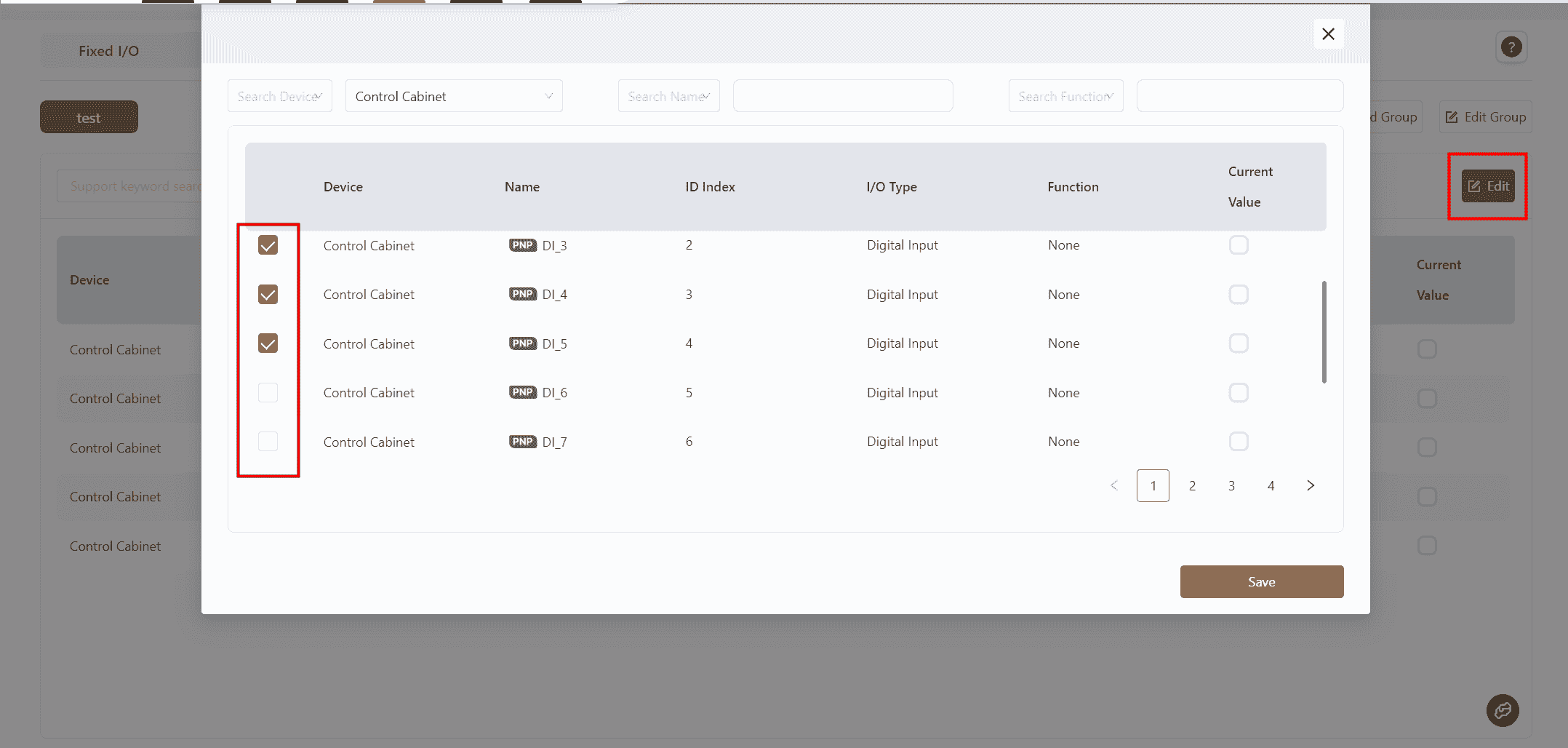
- In the pop-up box, select the required I/O according to actual needs:
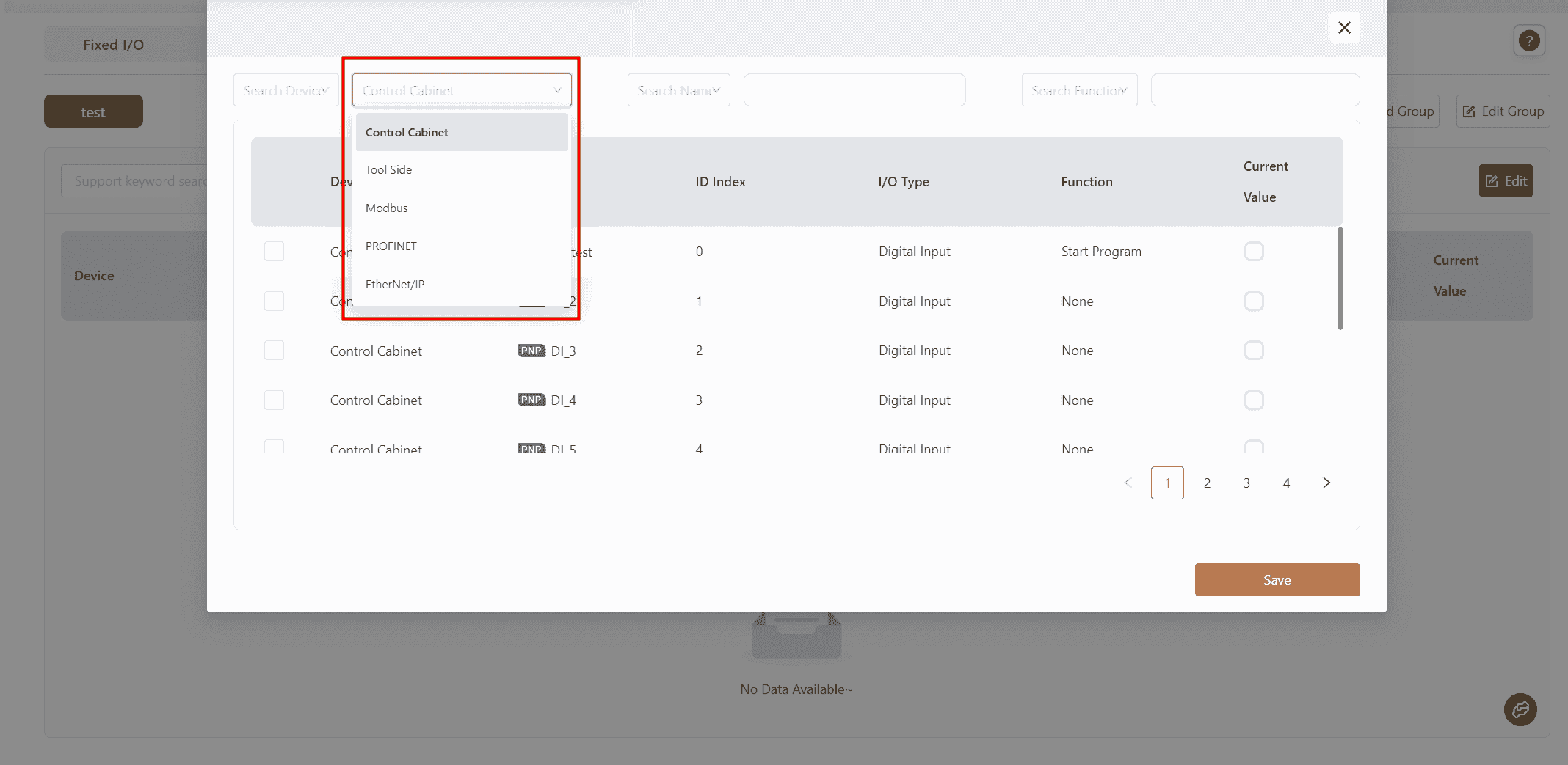
You can select the I/O category from the drop-down menu in Search Device.
Or directly search for the required I/O by keyword in Search Name and Search Function.
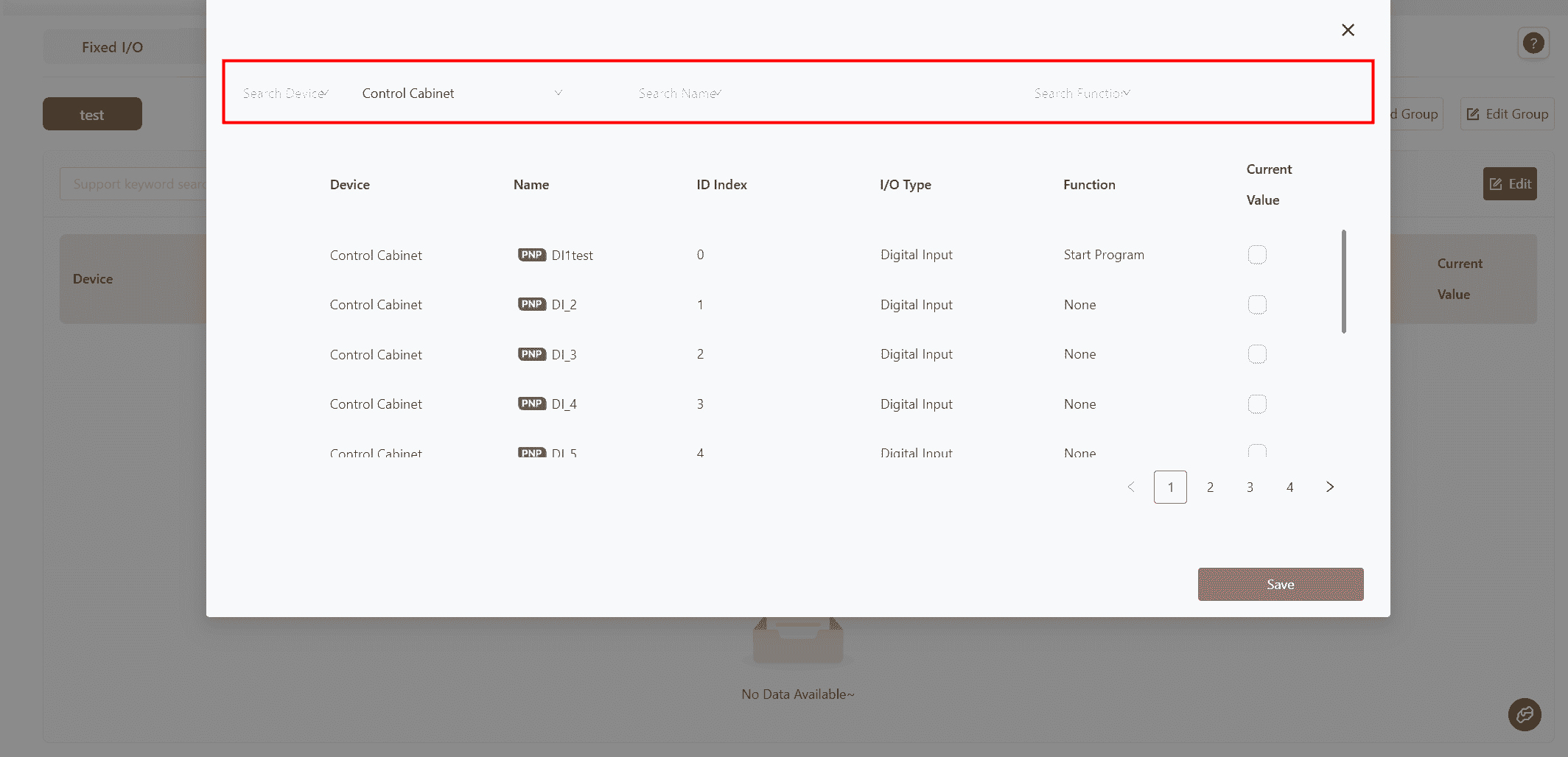
- Select the desired I/O and click
Save.
Note:
Different I/O can be selected simultaneously from different devices.
- After saving, the selected I/O will belong to the same group and be displayed on the same interface.
- Clicking
Editwill bring up a selection box where users can deselect previously selected I/O items.
- Clicking
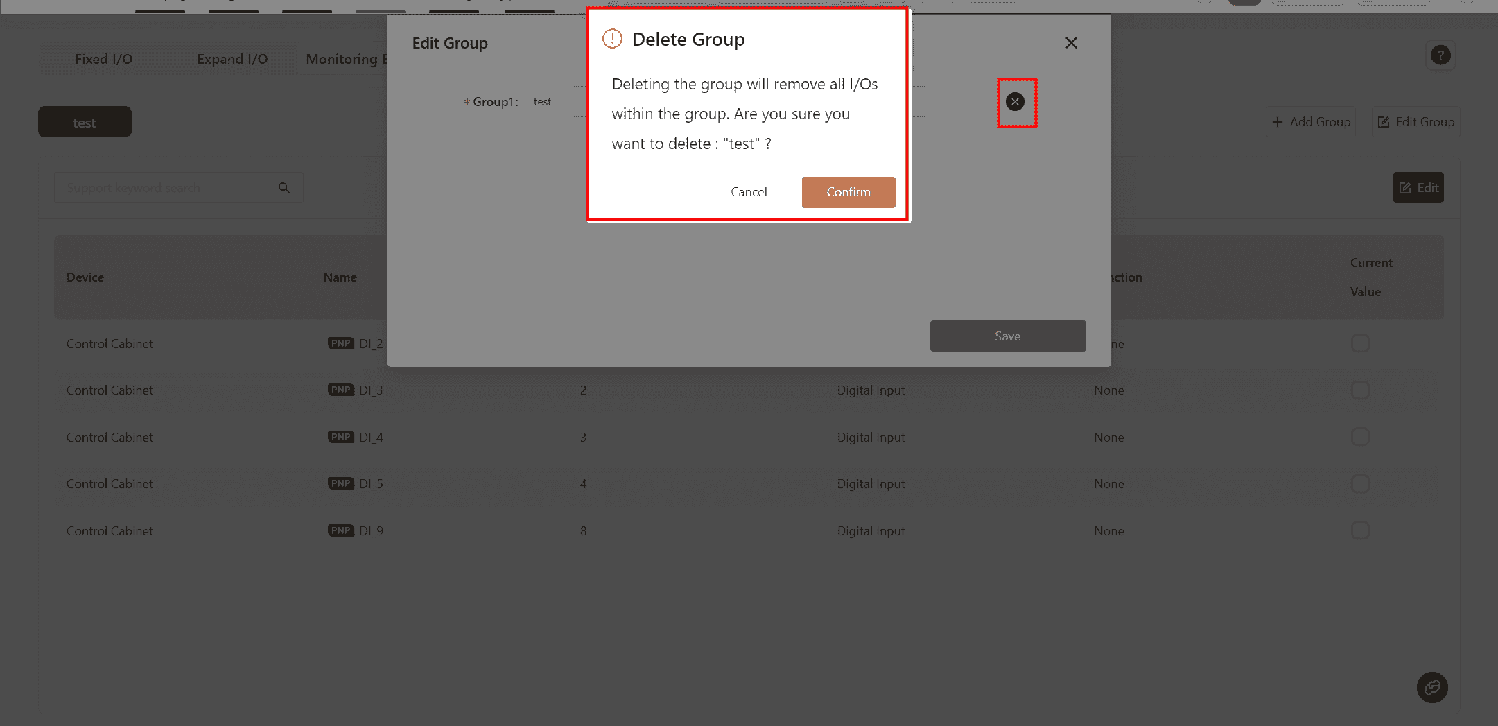
Edit Groupwill bring up an editing box where users can modify the group name or click×to delete the current group.
- As with other I/O, the configured monitoring board content can also be viewed on the
Programpage.