Settings
Users can set System Settings, Operation Settings, Safety Settings, Program Settings, Hardware and Communication and Hardware Interface Settings in this interface.
For detailed information, please see the content below.
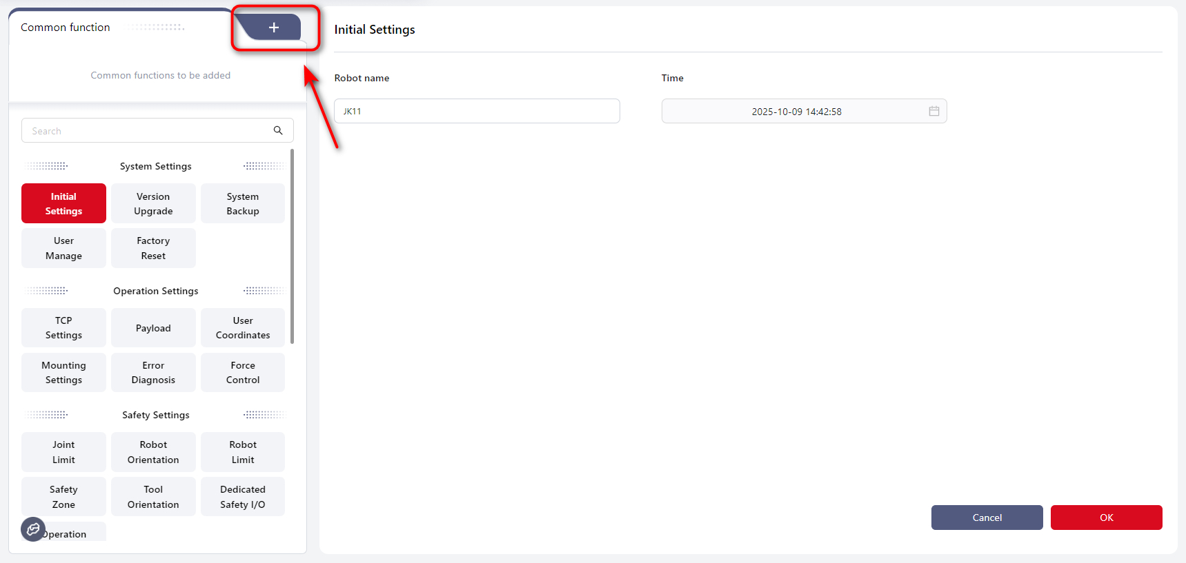
Common Functions
Users can add their most frequently used functions here by clicking +:
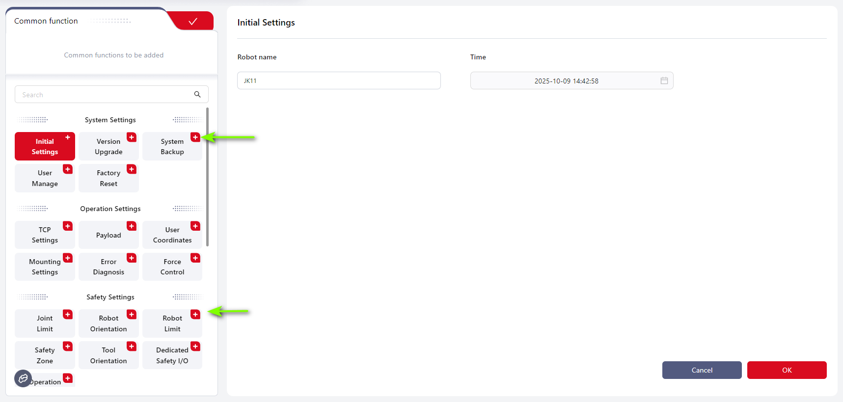
Then click the + on function box:
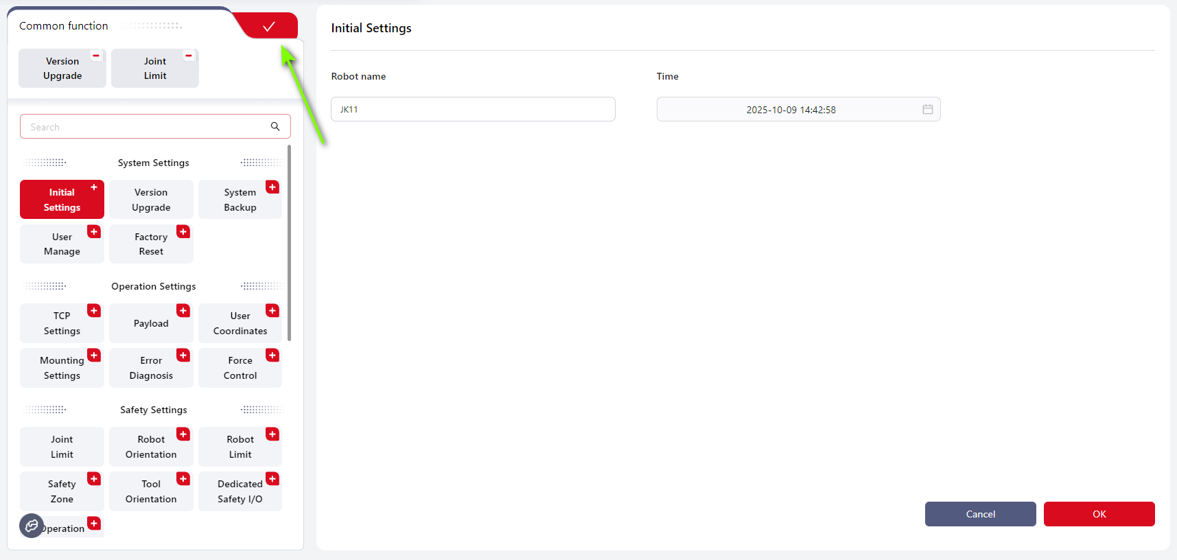
The selected function boxes will be displayed in Common functions, then click √:
System Settings
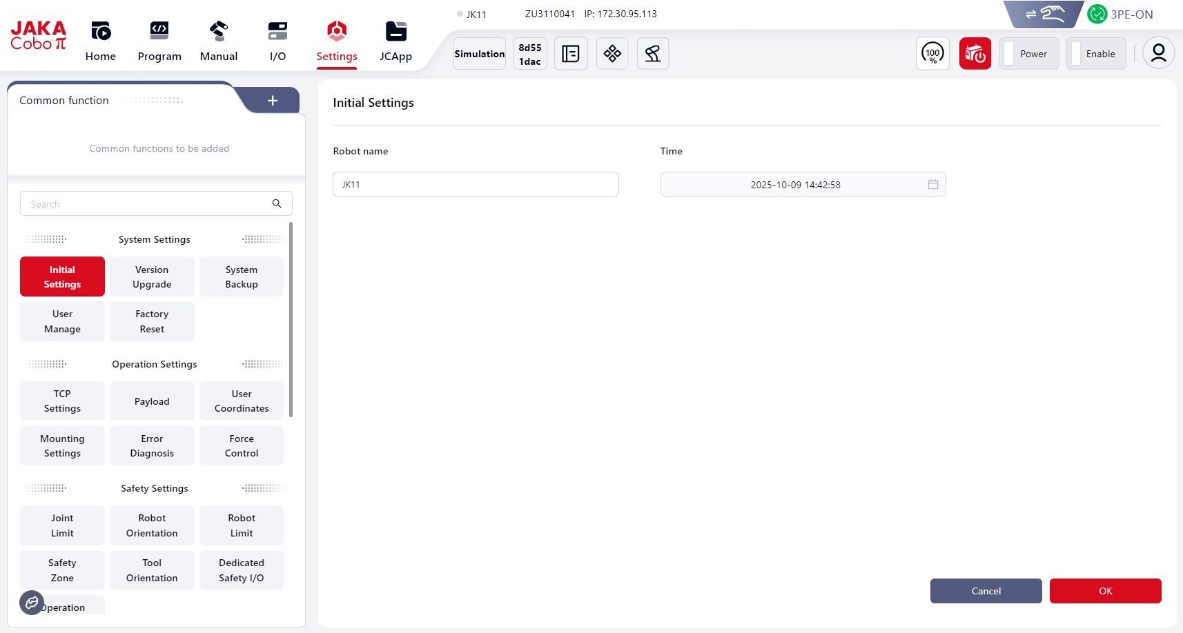
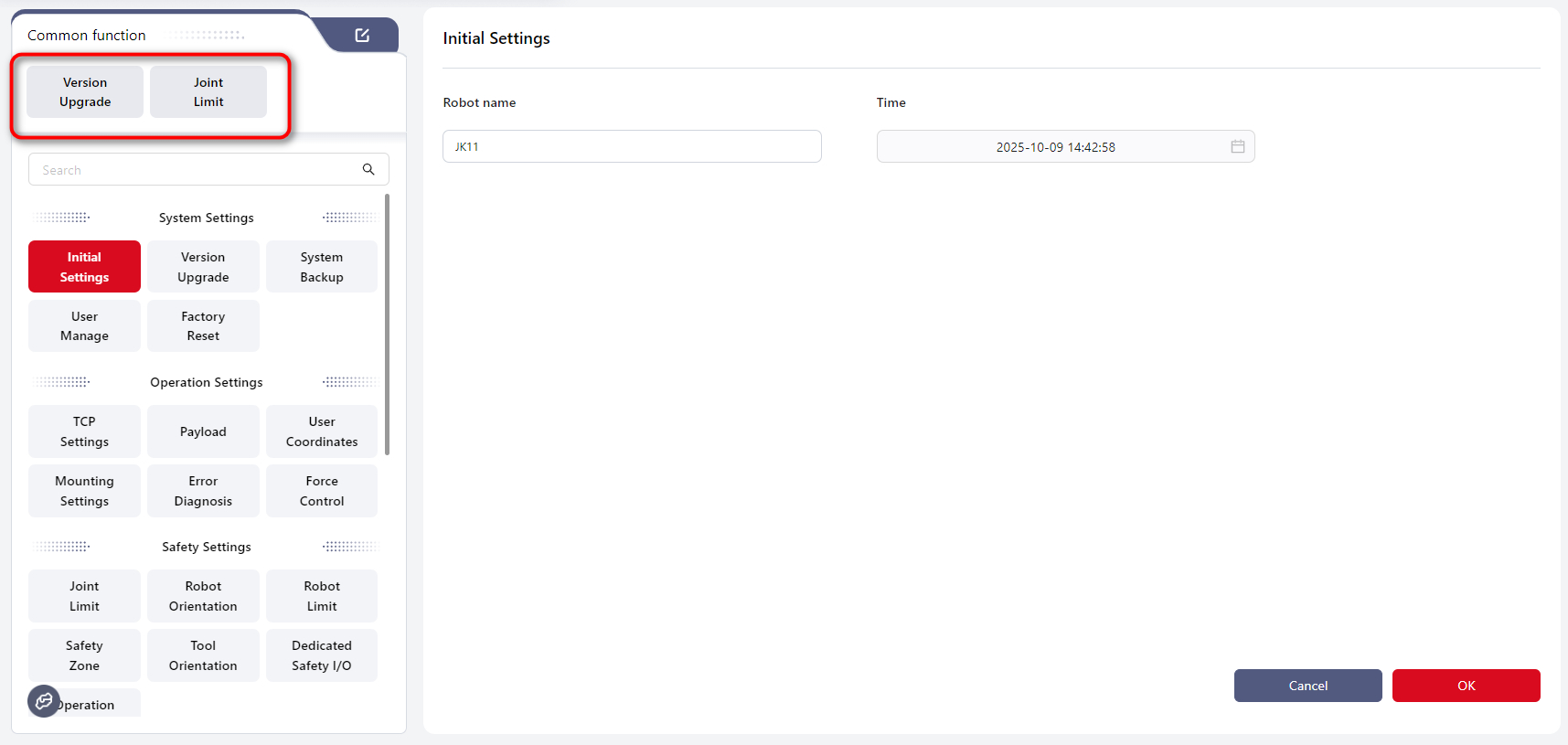
Initial Settings
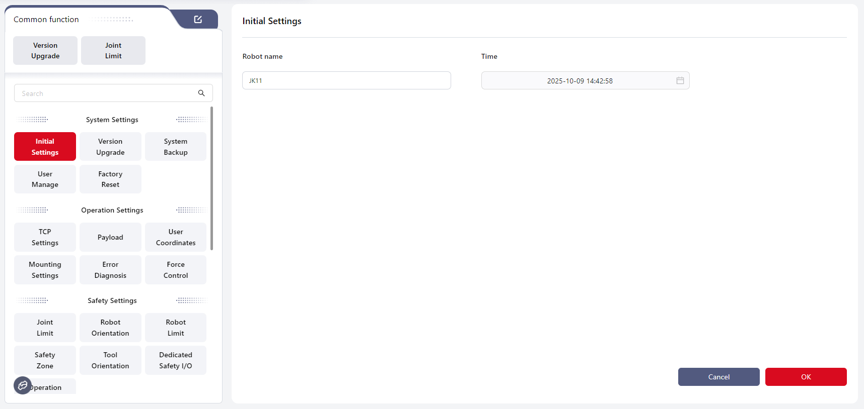
Enter a custom robot name in Robot name. The name must not contain any special characters except the underscore.
Set the system time in Time.
Click OK to apply the settings.
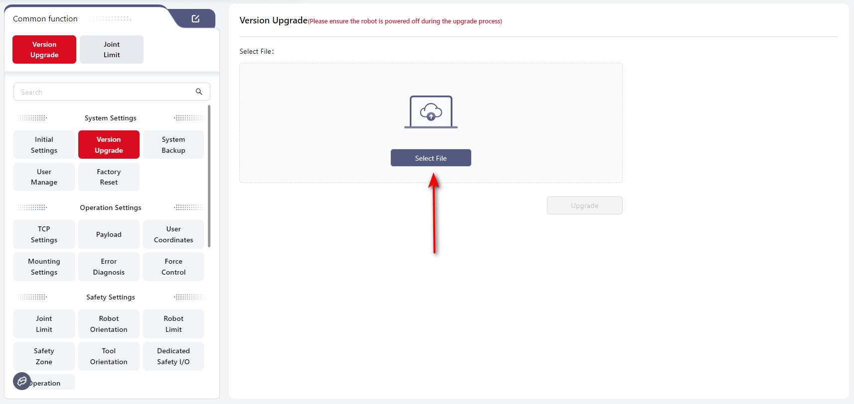
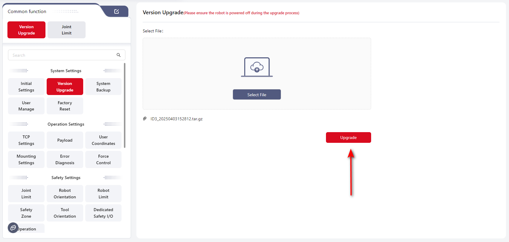
Version Upgrade
Users can upgrade the controller, SCB, and servo versions of the robot on this interface.
Click Select File, choose the upgrade package from the local folder, and then click Upgrade.
Note:
The correct upgrade order is: Controller → App → SCB → Servo.
If you only need to upgrade one component, upgrade that component directly.
If multiple components need upgrading, follow the above order.
Regular Upgrade
If you are upgrading a single component, follow these steps:
- Download the upgrade package to the local device.
- Open Coboπ and connect to the robot. Ensure the robot is powered off and disabled.
- Click
Select File, locate and upload the upgrade package. The package file extension must be.tar.gz(Do not rename the upgrade file; keep its original name). - When upgrading the controller, it will automatically restart. The upgrade is complete when the restart finishes and the handle light turns blue.
- After upgrading the servo, the system will prompt you to log in again. You can power on directly after logging in.
- When upgrading the SCB, an upgrade progress window will appear. After the upgrade completes, the controller will shut down. Press and hold the handle power button for 3–5 seconds to restart the control cabinet.
One-click Upgrade
If the upgrade package includes the controller, SCB, and servo, follow these steps:
- Download the upgrade package to the local device.
- Open Coboπ and connect to the robot. Ensure the robot is powered off and disabled.
- Click
Select File, locate and upload the one-click upgrade package. The package file extension must be.jaka(Do not rename the upgrade file; keep its original name).
After a successful upgrade, the system will restart automatically. Log in again after the restart to complete the process.
System Backup
Backup User Data
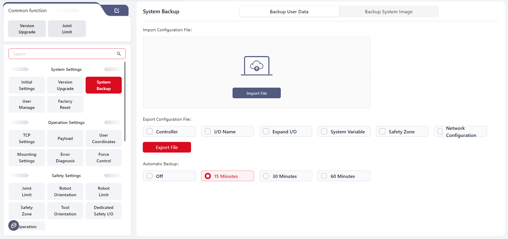
Users can import and export configuration files and set up scheduled automatic program backups on this interface.
Note:
Configuration file: User-defined configuration parameters modified during robot use, including controller settings, I/O names, dynamic I/O, system variables, and safety zones.
Import Configuration File
Click Import File, select the path where the configuration file is located, and click OK to complete the import.
After importing the configuration file, a pop-up window will ask whether you want to restart. Click Confirm to restart the system automatically.
Note:
Make sure the controller versions are consistent when importing configuration files. Importing files from different versions may cause controller malfunctions.
Export Configuration File
Select the type of configuration file you want to export, click Export File, choose the save path, and click OK to complete the export.
Automatic Backup
When scheduled automatic program backup is enabled, Coboπ will start timing after each program modification and automatically save a backup when the preset backup time is reached.
The backup file name format is: ProgramName.SystemTime
You can view backup files in Programming interface by selecting File → Backup.
Backup files cannot be executed directly. To run a backup, open the backup file and save it as a new file before executing.
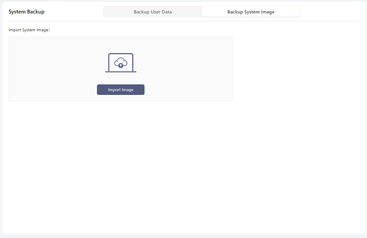
Backup System Image
Users can restore the system image using an external USB drive.
Tips
Due to safety concern, only Import System Image is supported. And the image should be the standard image provided by JAKA.
if you want to back up system image, please contact JAKA technical service team.
Prepare Image USB
- Insert the USB drive.
- Use an image tool to write the iso file to the USB drive.
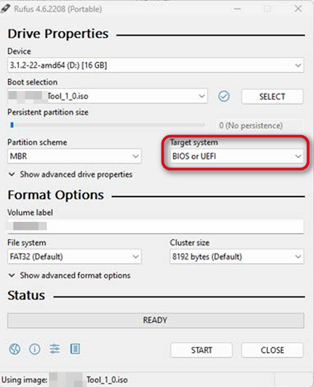
- Copy the image file and signature file to the USB drive.
Restore System Image
Attention:
Do not power off the device during image restoration, as this may cause system damage.
Please follow the steps below:
- Insert the USB drive containing the system image.
- Tap
Import Image. - In the pop-up window, select the image file to import.
- Enter the password (the default password of Administrator).
- Tap
Confirm. - The system starts verification. The page displays Verifying. Once the restoration starts, the system switches to the login page and shows the restore progress. The whole process should last for 15-30 minutes.
- When the restoration is complete, the system restarts automatically.
User Manage
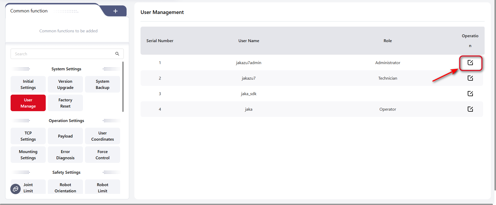
On this interface, users with the Administrator role can modify the login passwords for different roles.
The default administrator password is: jakazuadmin
Please keep the new password safe. If it is forgotten, contact JAKA technical support team to reset it, or use the reset button on the control cabinet (refer to the Hardware Manual for details).
If the password is entered incorrectly multiple times, the account will be temporarily locked. For example: if the wrong password is entered five times within ten minutes, the account will be locked for ten minutes.
Please note:
The jaka_sdk is specified for SDK users.
For details, please refer to the SDK user manual.
Factory Reset
Note:
When performing this operation, ensure the robot is powered off and disabled.
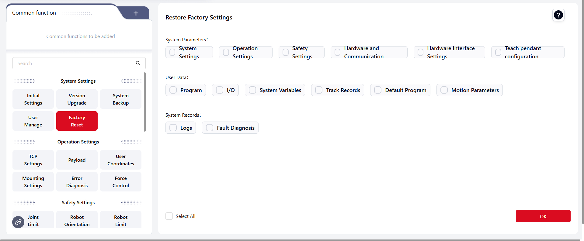
On this interface, users can choose specific options to restore to factory settings or click the Select All button in the to reset all options in the list.
After selecting the desired options, click Confirm,there will be a popup window:
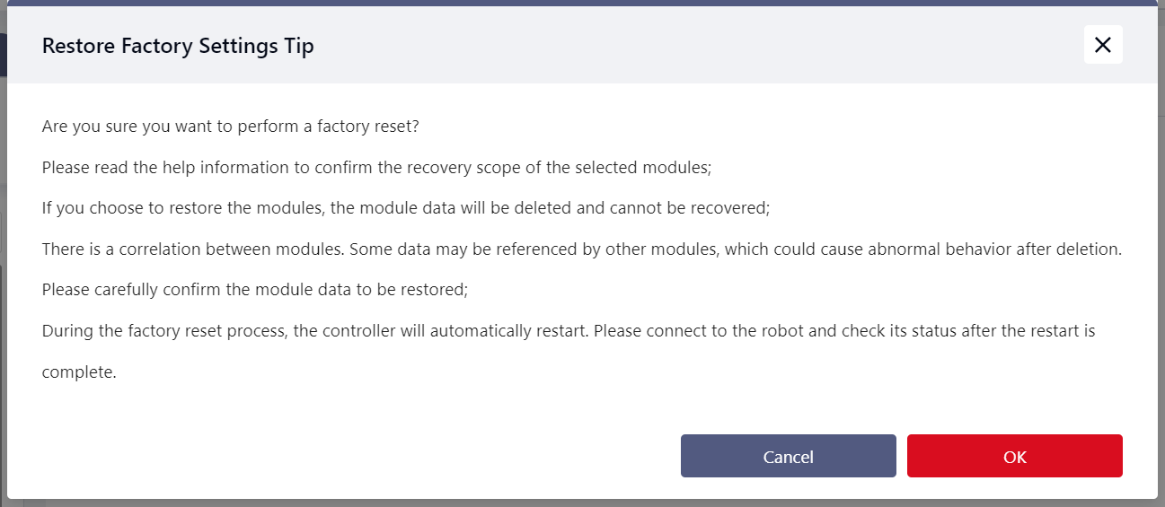
Click Confirm again, then enter the administrator password:
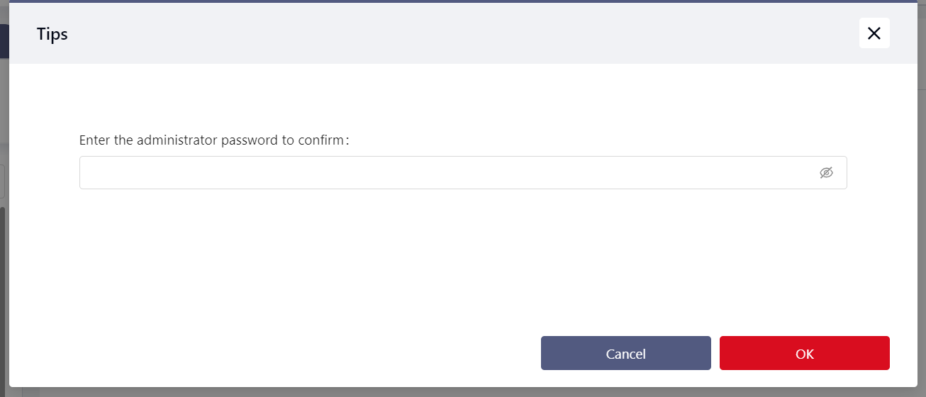
After entering the password, click Confirm. The page will display a prompt indicating that the restoration is in progress.
Afterwards, the robot restarts, and the restore is successful after the reboot.
Detailed descriptions are as follows:
System Parameters
- System Settings:
- Robot Name: Restored to "JKROBOT".
- Network Settings: Reset to obtain IP address automatically.
- Add-on Programs: Remove all add-ons except "System_Addon".
- User Management: Reset to default username and password.
- Operation Settings:
- TCP Settings: Reset TCP names and parameters to default values.
- Payload Settings: Manual input mode data reset to 0; clear auto-detection results.
- User Coordinate Settings: Reset user coordinate names and parameters to default values.
- Installation Settings: Clear set installation angles.
- Sensor Settings
- Safety Settings:
- Joint Limits: Restore default joint limits for the current robot model.
- Robot Postures: Reset all configured robot postures, including factory orientation, open orientation, initial orientation, initial orientation error, and motion speed.
- Robot Restrictions: Reset all robot-related restrictions to default values.
- Safety Zones: Clear all safety zone settings.
- Tool Orientation: Clear all tool orientation settings.
- Dedicated Safety I/O: Clear all safety I/O settings.
- Three-position Enable Settings.
- Hardware and Communication:
- Modbus Parameter Settings: Reset Modbus TCP/IP to port 6502.
- End Sensor: Reset all settings related to the end sensor to default values.
- PROFINET Settings: Disable PROFINET and clear device parameters.
- EtherNet/IP Settings: Disable EtherNet/IP and clear device parameters.
- Auxiliary Hardware Settings: Reset all related settings to default values.
- External Axis: External axis and its related parameters.
- Hardware Interface Settings: Reset network interface, Wi-Fi, auxiliary settings, brake voltage and control cabinet I/O to default settings.
- Teach Pendant Configuration
User Data
- Programs:
- Delete all programs.
- Delete all program waypoint data.
- I/O:
- Clear all configured functional I/Os.
- Clear all functional I/O names.
- Clear parameters related to functional I/Os.
- Clear speed multiplier configurations.
- Clear extended I/O configurations.
- Delete all added extended I/Os.
- Reset auto-reconnect configurations to default values.
- System Variables: Delete all system variables.
- Trajectory Records: Delete all trajectory record files.
- Default Programs: Restore all configurations on the "Default Programs" interface.
- Motion Parameters: Restore trajectory motion parameters and servo mode parameters to default values.
- Trajectory motion parameters: blending parameters, torque limit, acceleration and jerk.
- Servo mode parameters:
System Records
- Logs: Clear all content in the "Logs" interface.
- Fault Diagnosis: Delete all diagnostic folders and files.
Operation Settings
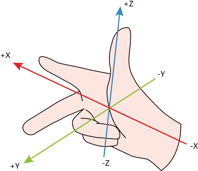
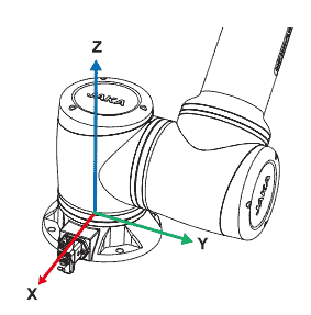
When operating the robot, several coordinate systems are available, including the World Coordinate System, Flange Coordinate System, Tool Coordinate System, and User Coordinate System.
The World and Flange coordinate systems are default systems, while the Tool and User coordinate systems are user-defined.
All coordinate systems follow the right-hand rule, as shown in the figure below:
TCP Settings
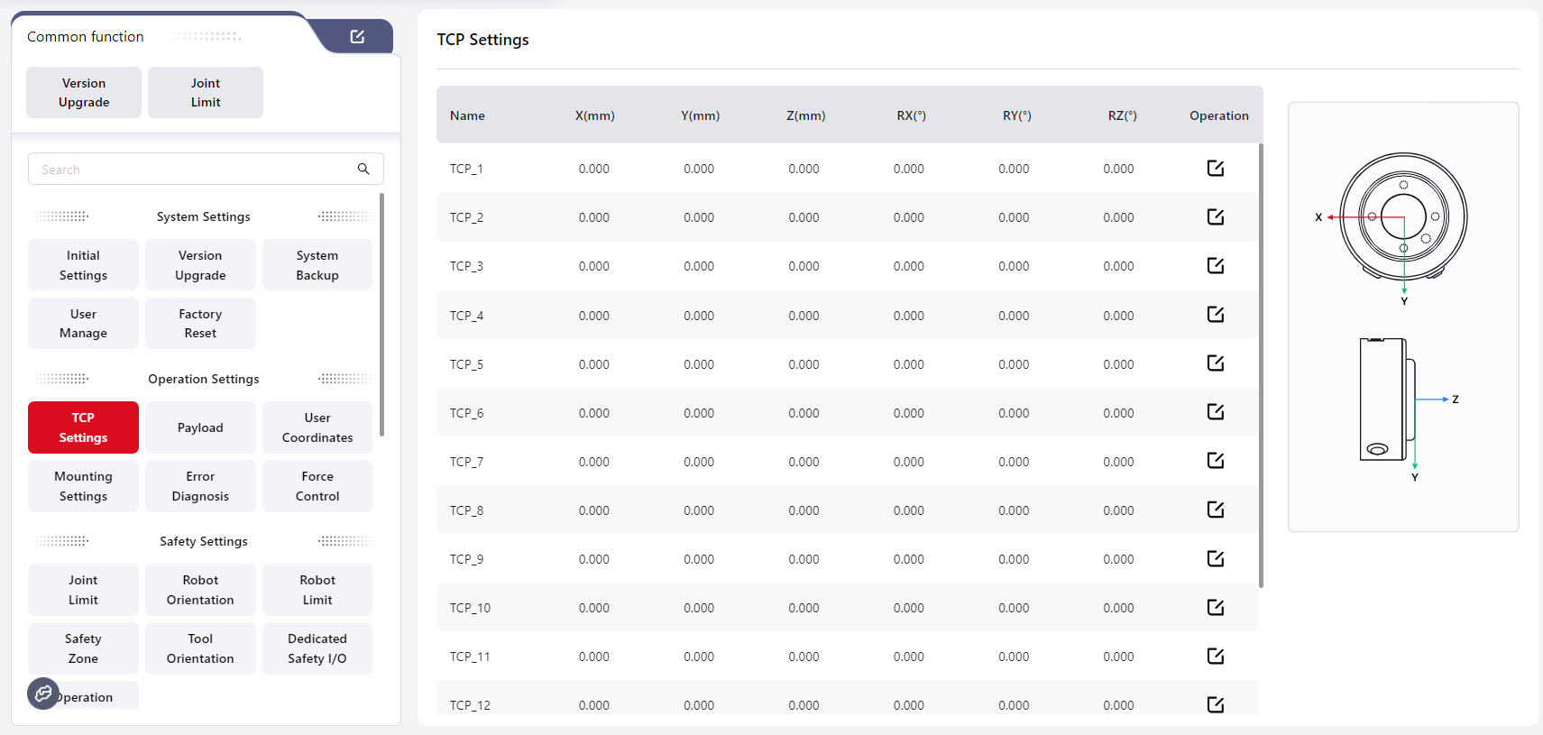
The Tool Coordinate System is established with the Tool Center Point (TCP) as the origin. It represents the position of the robot's tool, requiring manual calibration. In the context of JAKA Coboπ, TCP refers to the Tool Coordinate System. When the robot's tool is replaced, the Tool Coordinate System needs to be recalibrated.
The robot's end position refers to the Cartesian coordinates of the robot's end center point in the current user coordinate system. The robot's end orientation represents the orientation of the Tool Coordinate System in the current user coordinate system, expressed using the Roll-Pitch-Yaw (RPY) method, displayed as RX RY RZ on the interface.
The Flange Coordinate System is the robot's default tool coordinate system. It uses the robot's flange center as the coordinate system origin, with the flange face pointing in the positive Z-axis direction. The connection between the flange center and the TIO points in the negative Y-axis direction, and the positive X-axis direction is determined by the right-hand rule.
The diagrams below illustrate this:
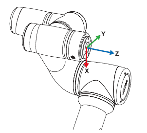
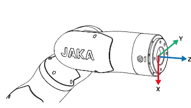
Since the flange coordinate system parameters cannot be modified, the TCP is usually set at the end of the robot's end-effector (e.g., the center of the gripper or suction cup) in applications where high precision is required.
JAKA Coboπ supports the configuration of 15 editable TCP parameters.
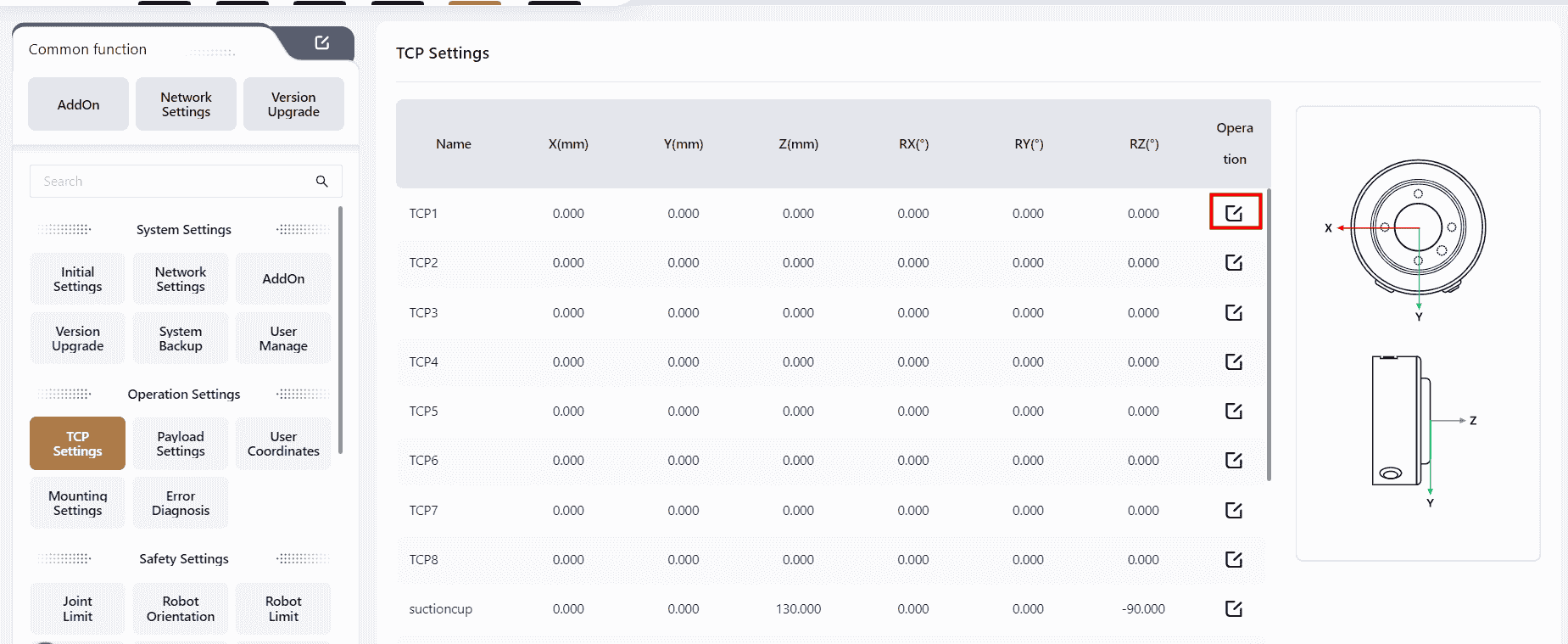
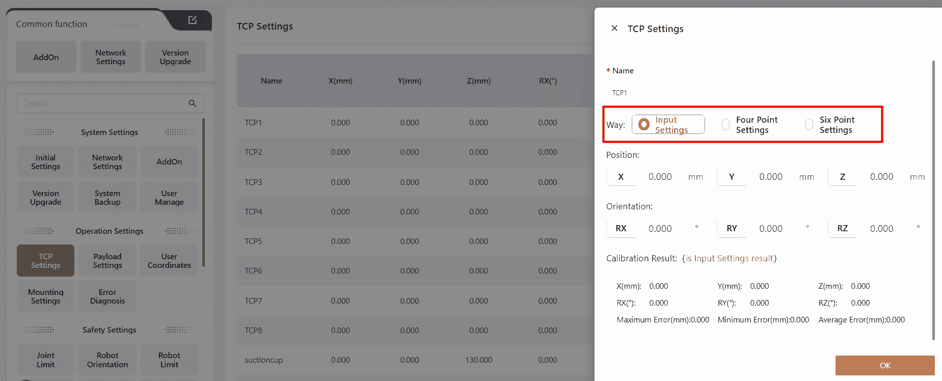
Users can choose from three different methods to set the TCP based on their needs.
Input Settings
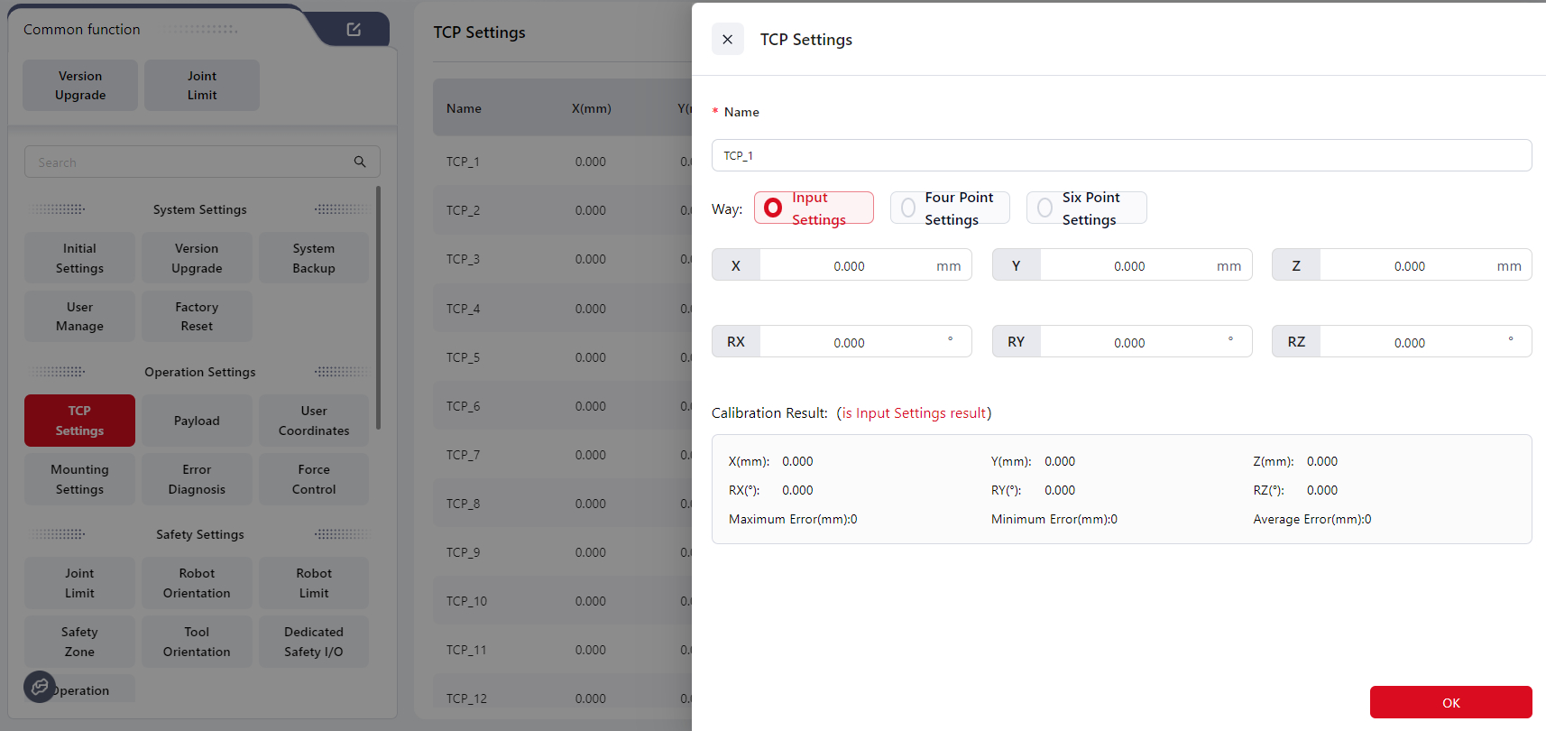
Enter the data directly in the corresponding fields to set the values.
After calibration, the calibration results and errors will be displayed.
Four-Point Method
Tips
Select a fixed point in space and move the robot so that the TCP reaches this point with four different orientations. This allows the system to calculate the desired pose offset of the tool coordinate system relative to the flange coordinate system. Refer to the animation next to the setup box for guidance.
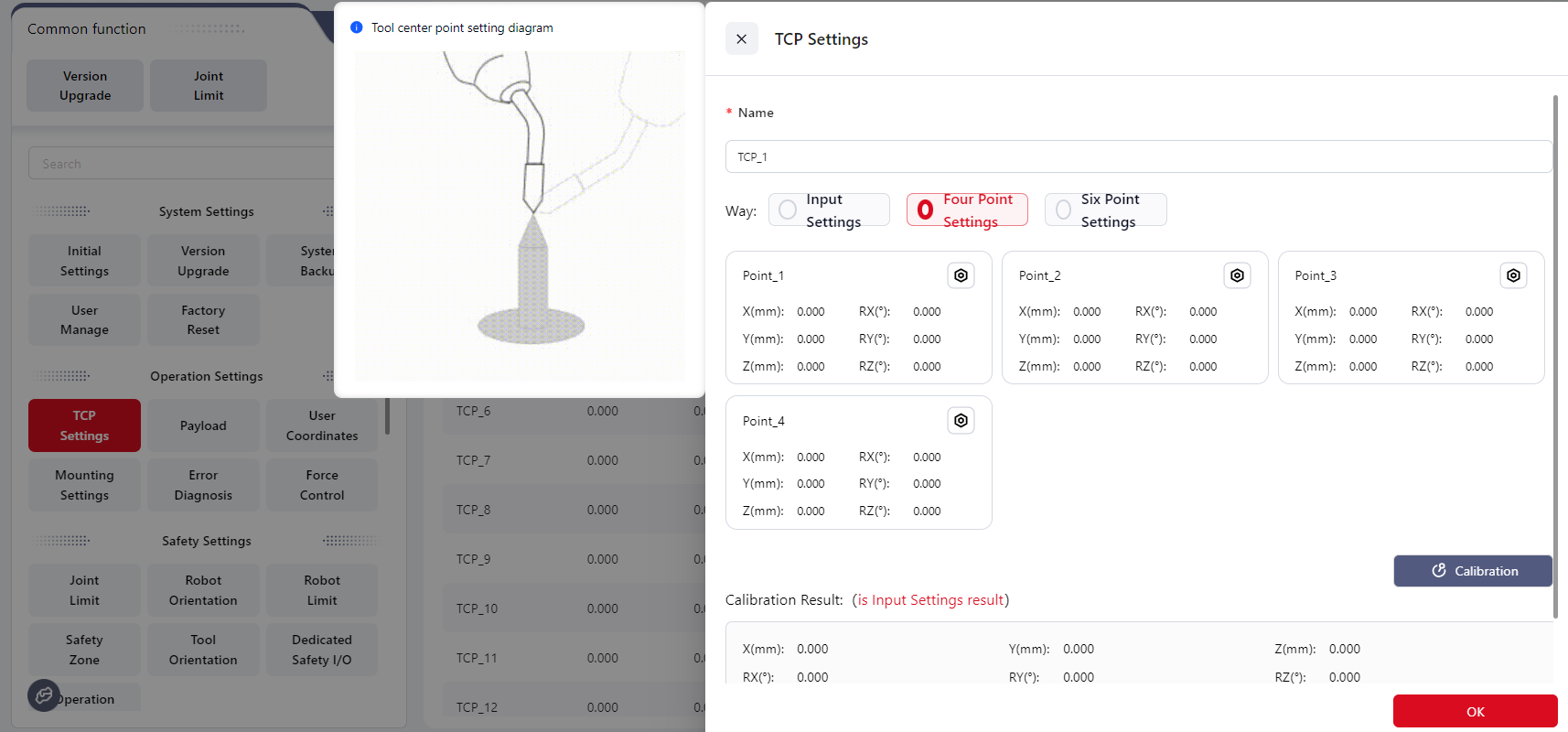
Steps:
- Select a fixed reference point within the robot’s reachable range (e.g., the tip of a cone).
- Click Position_1, move the robot’s end effector to the reference point, then click Confirm.
- Click Position_2, move the end effector to the same reference point using a different joint configuration, then click Confirm.
- Click Position_3, move the end effector to the same reference point with another different configuration, then click Confirm.
- Click Position_4, move the end effector to the same reference point with a fourth unique configuration, then click Confirm.
- Click Calibrate to obtain the parameters of the desired tool coordinate system.
- After calibration, the results and errors will be displayed.
Six-Point Method
Tips
Based on the four-point method, two additional points are used to determine the TCP axis direction. This enables automatic calculation of both TCP position and orientation, thereby defining the desired tool coordinate system.
The six-point method is typically used when the tool axis is not perpendicular or parallel to the robot’s flange axis. It ensures that the Z-axis of the tool coordinate system aligns with the tool’s main axis.
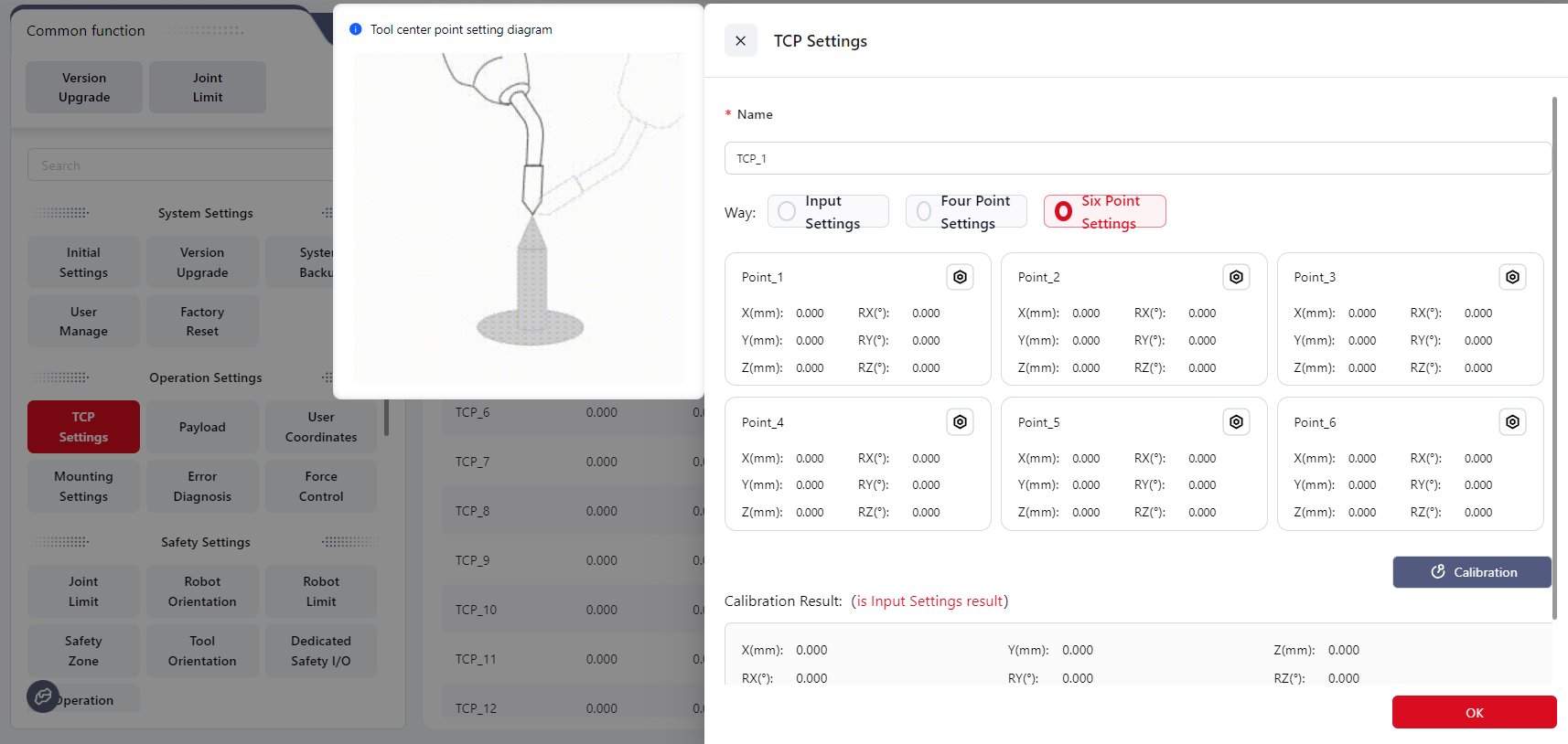
Steps:
- Select a fixed reference point within the robot’s reachable range (e.g., the tip of a cone).
- Click Position_1, move the robot’s end effector to the reference point, then click Confirm.
- Click Position_2, move the end effector to the same point with a different orientation, then click Confirm.
- Click Position_3, repeat with another unique orientation, then click Confirm.
- Click Position_4, move the end effector to the same reference point again with a new orientation, then click Confirm. This point will serve as the origin of the desired tool coordinate system.
- Click Position_5, keeping the orientation of Position_4 unchanged, move the tool along the positive Z-axis of the desired tool coordinate system for a short distance, then click Confirm.
- Click Position_6, keeping the orientation of Position_5 unchanged, move the tool within the X–Z plane of the desired tool coordinate system for a short distance, then click Confirm.
- Click Confirm to calculate the parameters of the desired tool coordinate system. The line connecting Position_4 and Position_5 defines the positive Z-axis direction.
- After calibration, the results and errors will be displayed.
Payload
Tips
Payload refers to the total mass and center of gravity of all objects attached to the robot’s end.
Properly setting the load allows the controller to accurately calculate the robot’s working conditions.
When the load is set correctly, and the robot flange faces downward, the robot’s end remains stable and does not drift when entering drag mode.
Warning
Please set the load correctly. If the actual load differs from the configured value, the controller may falsely detect collisions, stop unexpectedly, or even become damaged.
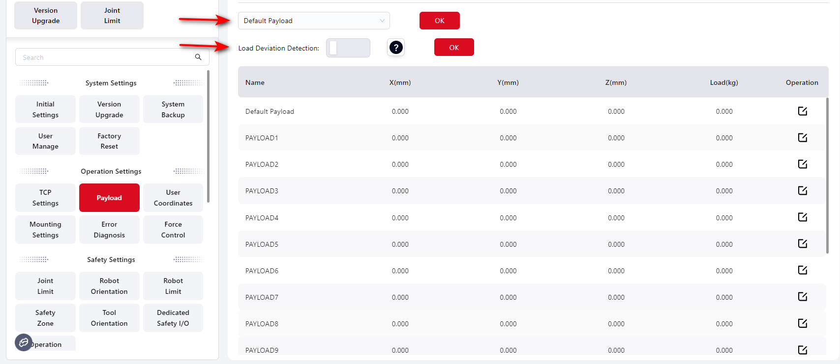
On this interface, users can configure the global load settings for the system.
If Load Deviation Detection is enabled:

Tips
Warning Threshold – The maximum value you can set here is the robot model’s rated maximum load. When enabled, the system checks for load deviation every time the robot is powered on. If the deviation ≥ the warning threshold, an abnormal warning will appear at the top of the interface.
Drag Limit Threshold – The maximum value is also limited by the robot’s rated load. When entering drag mode, if the deviation ≥ the drag limit threshold, the robot cannot enter drag mode.
This interface allows you to configure 1 default payload and up to 15 additional payloads.
The default payload is set to 0 kg at the flange center.
Users can select a payload name from the dropdown list or click the edit icon to open the individual payload setup page.
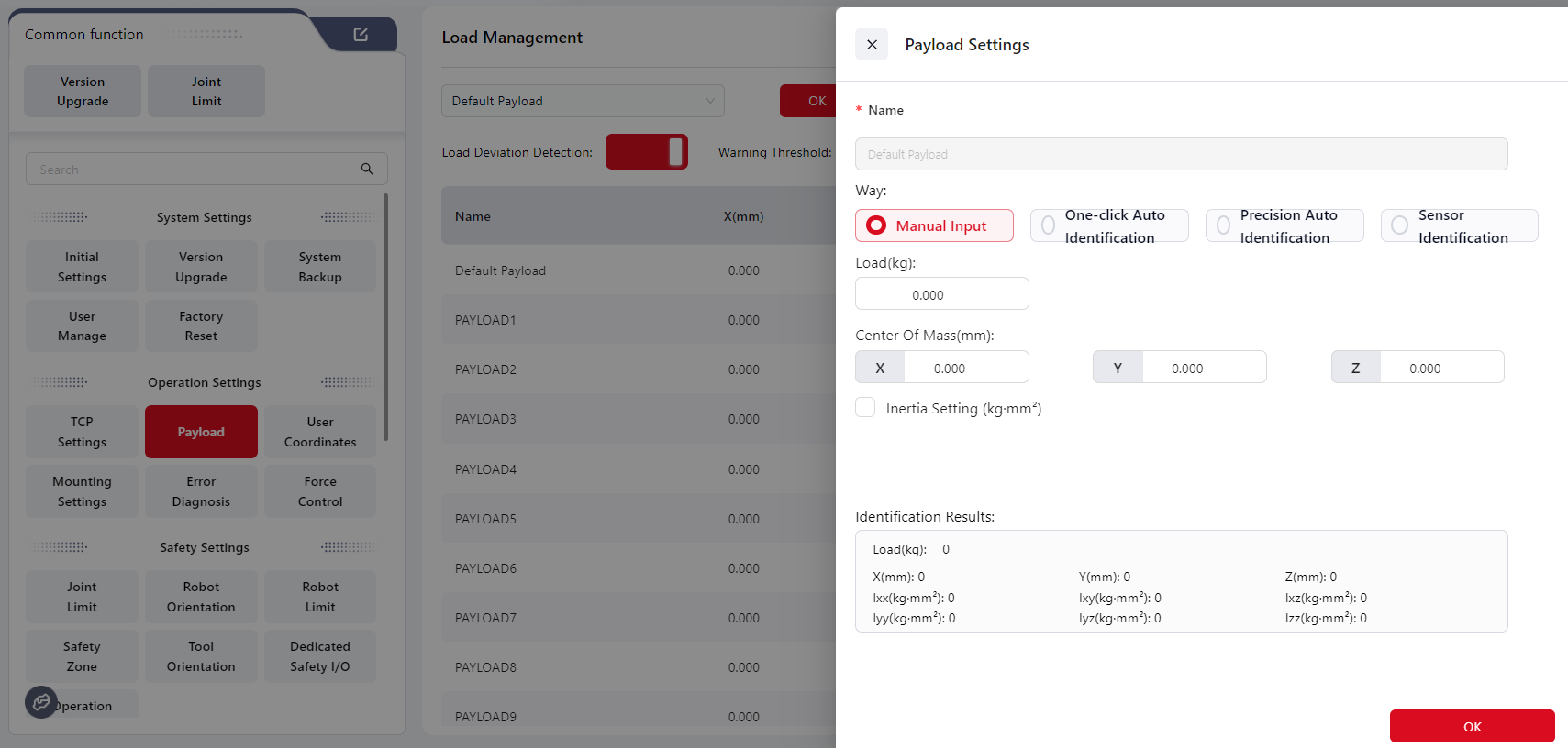
Manual Input
Enter the payload data obtained from calculations or measurements.
Fill in the Center of mass, then click Confirm to complete the setup.
Tips
The center of mass position is defined relative to the robot flange center, and the X, Y, and Z values are measured in the flange coordinate system.
It is recommended to use 3D design software for higher accuracy.
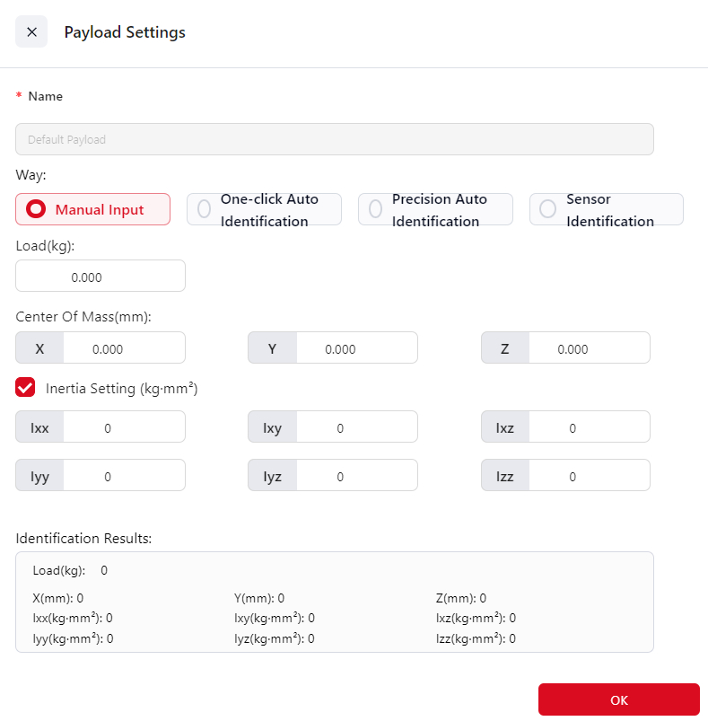
You can also click the icon to enter Inertia Settings:
One-Click Auto Identification
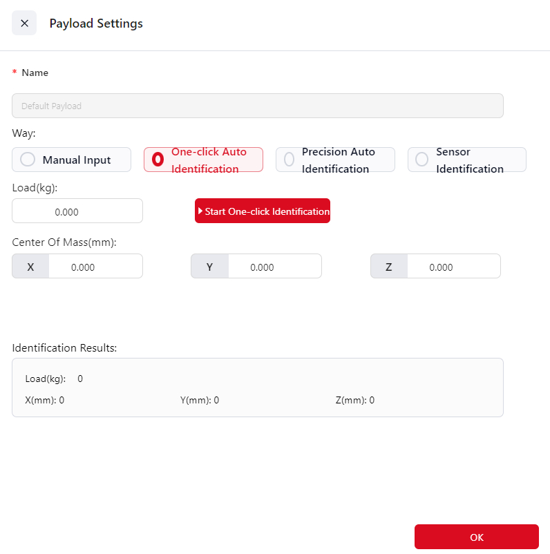
After the load is installed, click Start One-click Identification.
The system will display Load Identifying... during the process, and once completed, the icon will change to Identification Complete.
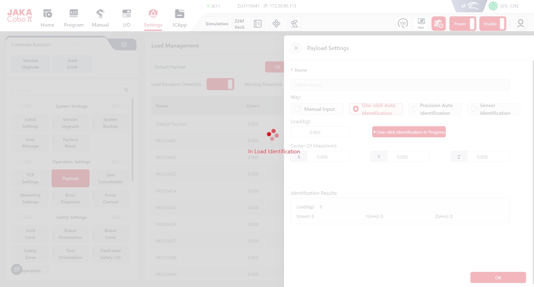
Users can still manually adjust the values in the input fields or view the Identification Results.
Warning
Always verify the identification results manually. DO not rely solely on automatic identification.
In particular, when the PAYload is very light or includes long cables, automatic identification results may be inaccurate.
In such cases, it is recommended to manually input the correct payload data.
Precision Auto Identification
The Precision Auto Identification mode calculates the payload and center of mass of the end load by comparing joint motion data (axes 3, 4, 5, and 6) under loaded and unloaded conditions.
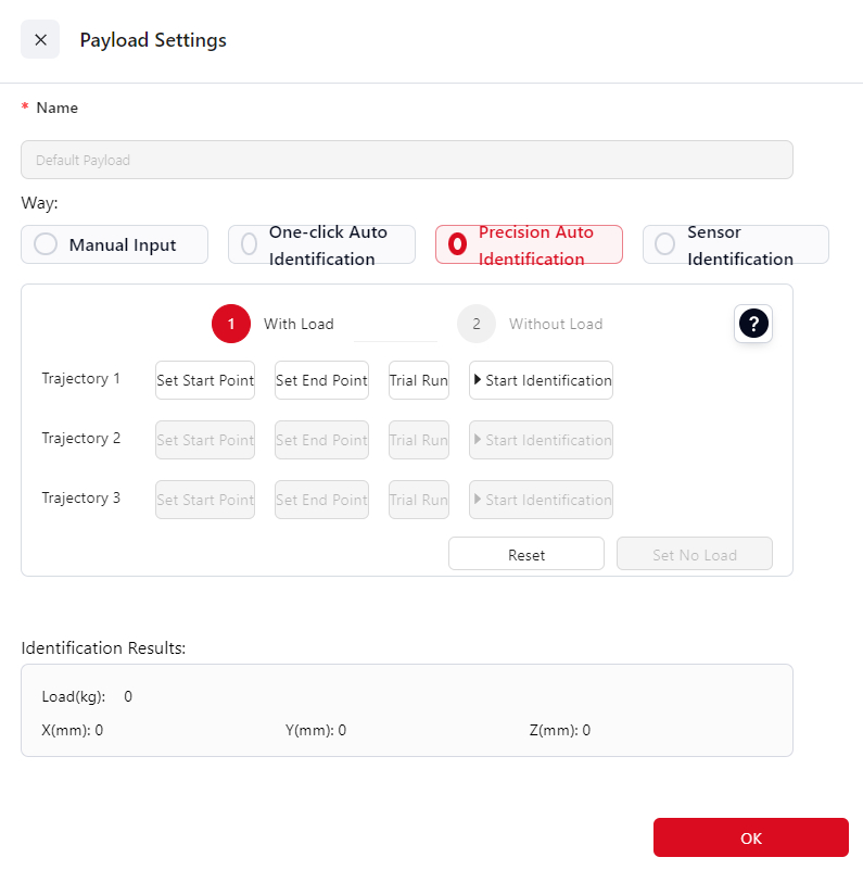
Steps:
Initially, the robot must execute the same trajectory in both loaded and unloaded states. Begin with the
With Load.Attach the load and move the robot to position (0°, 90°, 0°, 0°, 180°, 0°) with a vertical orientation. This position serves as the baseline pose for the recognition process.
Set Up
Trajectory 1:- Click
Set Start Point,Enter the manual control interface and configure the starting point.- For Trajectory 1, ensuring it meets these constraints: Joint 2 is 90°, Joint 3 is 0°, Joint 4 is within (-60°, 60°), Joint 5 is 180°, and Joint 6 matches Joint 4's angle. If any condition is unmet, a Coboπ pop-up will prompt correction.
- Once set, click
Confirm.
- Click
Set End Pointto enter manual control and set the point position.- The end point must match the start point conditions, with an additional requirement that Joint 4’s angle differs by at least 10° between start and end.
- Once set, click
Confirm.
- Click
Test
Trajectory 1:- Long press
Set Start Pointto return to the initial point. - Long press
Trial Runto move the robot from the start point to the end point, ensuring no interference along the trajectory.
- Long press
Identify
Trajectory 1:- Click
Start Identification - Upon trajectory completion, this button will show the Identification is complete.
- Click
Set Up
Trajectory 2:- Click
Set Start Pointto enter manual control and set the point position.- The initial point for Trajectory 2 must meet these requirements: Joint 2 at 90°; Joint 3 at 0°; Joint 4 between -60° and 60°; Joint 5 at 180°; Joint 6 at 90° greater than Joint 4’s angle. If any requirement is not met, Coboπ will display a prompt.
- Once set, click
Confirm
- Click
Set End Pointto enter manual control mode and set the point position- The end point must match the start point conditions, with an additional requirement that Joint 4’s angle differs by at least 10° between start and end.
- After setting, click
Confirm.
- Click
Test
Trajectory 2:- Long press
Set Start Pointto return to the initial point.. - Long press
Trial Runto move the robot from the start point to the end point, ensuring no interference along the trajectory.
- Long press
Identify
Trajectory 2:- Click
Start Identification - Upon trajectory completion, this button will show the Identification is complete.
- Click
Set Up
Trajectory 3:- Click
Set Start Pointto enter manual control and set the point position.- The initial point for Trajectory 3 must meet these requirements: Joint 2 at 90°; Joint 3 at 0°; Joint 4 at 0°; Joint 5 between 170° and 180°. If any requirement is not met, Coboπ will display a prompt.
- Once set, click
Confirm.
- Click
Set End Pointto enter manual control mode and set the point position.- The end point must meet these requirements: Joint 2 at 90°; Joint 3 at 0°; Joint 4 at 0°; Joint 5 between 180° and 190°, ideally totaling 360° with the initial Joint 5 angle; Joint 6 aligned with its initial angle. If any requirement is not met, Coboπ will display a prompt.
- After setting, click
Confirm.
- Click
Test
Trajectory 3:- Long press
Set Start Pointto return to the initial point. - Long press
Trial Runto move the robot from the start point to the end point, ensuring no interference along the trajectory.
- Long press
Identify
Trajectory 3:- Click
Start Identification - Upon trajectory completion, this button will show the Identification is complete.
- Click
After confirming completion of recognition for all three trajectories, remove the load, and click
Witout Loadto switch to Without mode. No need to reset the trajectories; proceed with recognition for each trajectory in unloaded mode.When both loaded and unloaded recognition are complete. A pop-up window will display the recognition results.
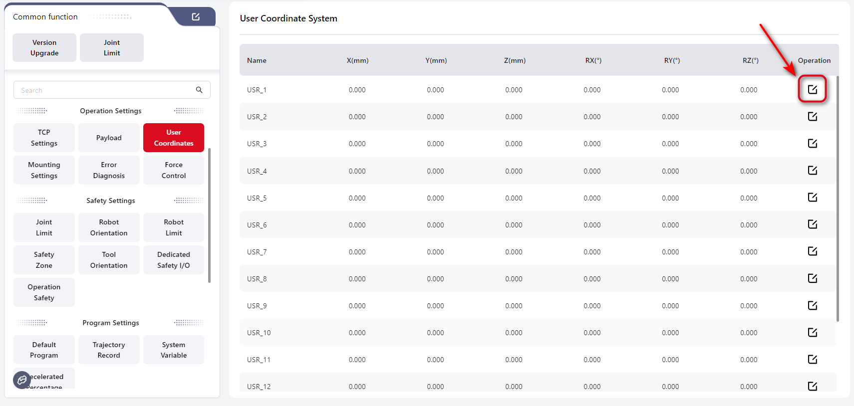
User Coordinate System
Tips
The User Coordinate System is established on a workpiece. It can be set by directly entering numeric values or by manually teaching points, from which the robot calculates the coordinate system parameters.
When the workpiece position changes, the user coordinate system must be recalibrated.
The World Coordinate System is the default user coordinate system, and its parameters cannot be modified. Its origin is located at the center of the robot base. In the upright installation, the direction perpendicular to the base and pointing toward the robot body is the positive Z-axis, the direction from the base center to the heavy-load connector is the positive X-axis, and the positive Y-axis is determined by the right-hand rule, as shown below:

JAKA Coboπ supports up to 15 editable user coordinate systems. Click the icon to enter the Settings page:
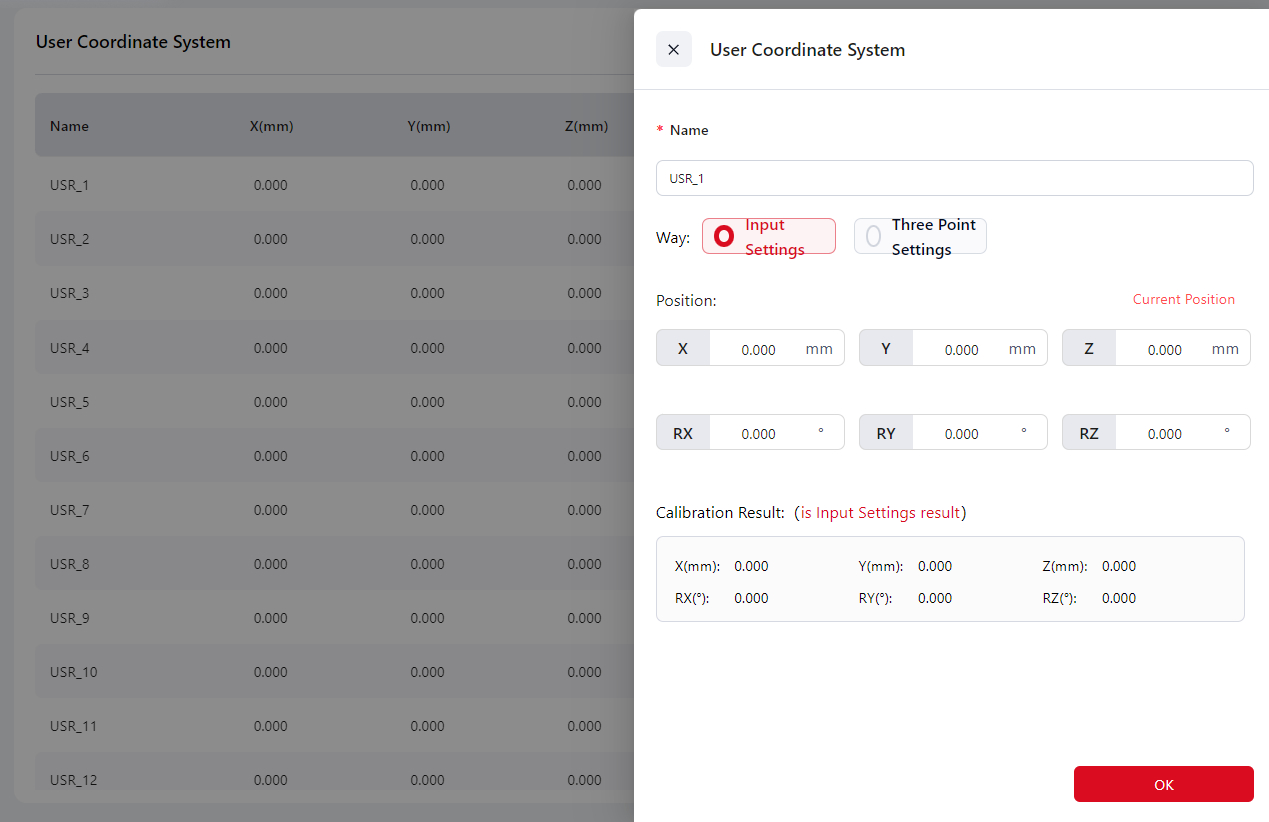
Input Settings
Enter the data into the corresponding box and click Confirm to complete the user coordinate system configuration. The calibration result will be displayed.
Three-Point Setting
Users can teach three position points. The robot will automatically calculate the X, Y, and Z directions of the desired user coordinate system based on these points.
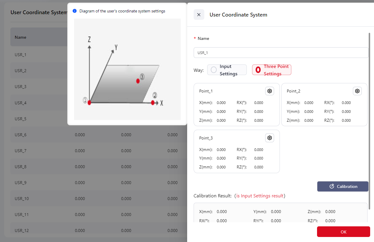
Click on any position within the Position Point box, and the page will automatically redirect to the manual operation page. The user can control the robot's movement on this page to set the three position points or directly use the robot's teaching method to set the points.
Point_1 This sets the origin of the user coordinate system.
Point_2 This sets any point in the positive X-axis direction of the user coordinate system.
Point_3 This sets any point in the first quadrant of the user coordinate system's XOY plane.
The coordinate system chosen during the three-point setup should remain consistent.
Once the points are set, the calibration results will be displayed.
Mounting Settings
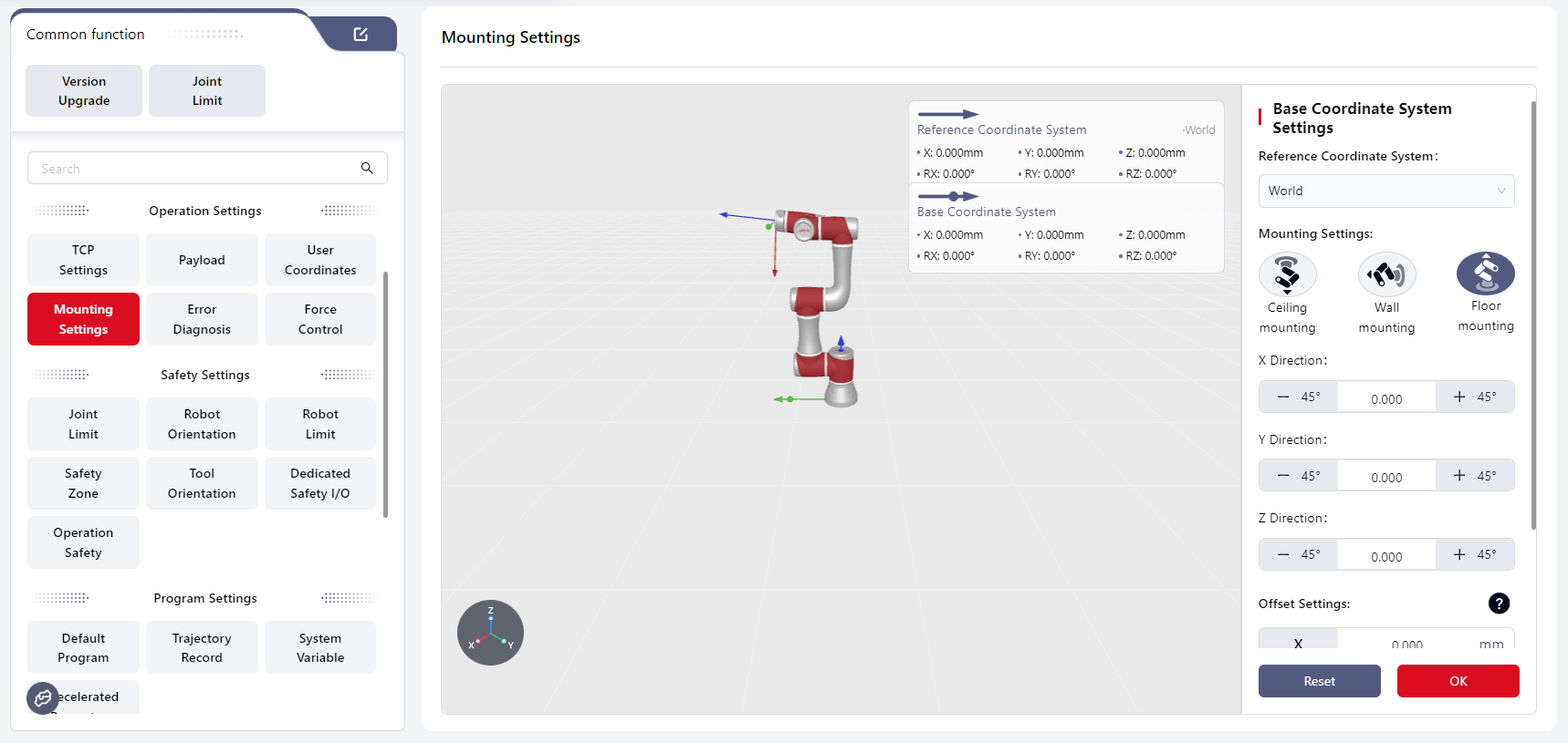
JAKA robots support mounting at any angle.
After mounting, the actual mounting angle must be entered on this page to ensure safe operation.
Steps:
- Select the current coordinate system in Reference Coordinate System. The 3D view will display the selected system.
- In Mounting Settings, select the actual mounting orientation of the robot.
- Adjust the robot model in the X/Y/Z Direction section to match the actual mounting orientation.
- Enter offset values for each axis in the Offset Settings section. Click ? for explanation.
- Click Confirm to apply the settings.
- Click Reset to restore default values:
- Reference coordinate system: World Coordinate System
- Mounting Settings: Floor mounting
- Direction values for X, Y, Z: 000.000
- Offset values for X, Y, Z: 0.000
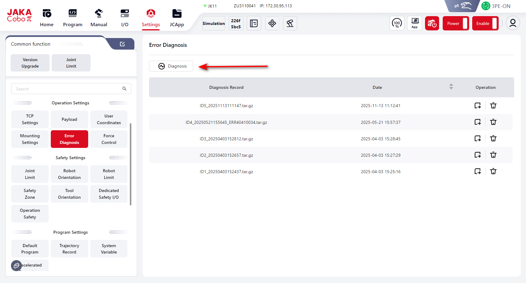
Error Diagnosis
When an error occurs, the controller automatically saves related information as a compressed file, named according to the system time at that moment.
These compressed files are displayed on the Error Diagnosis page:
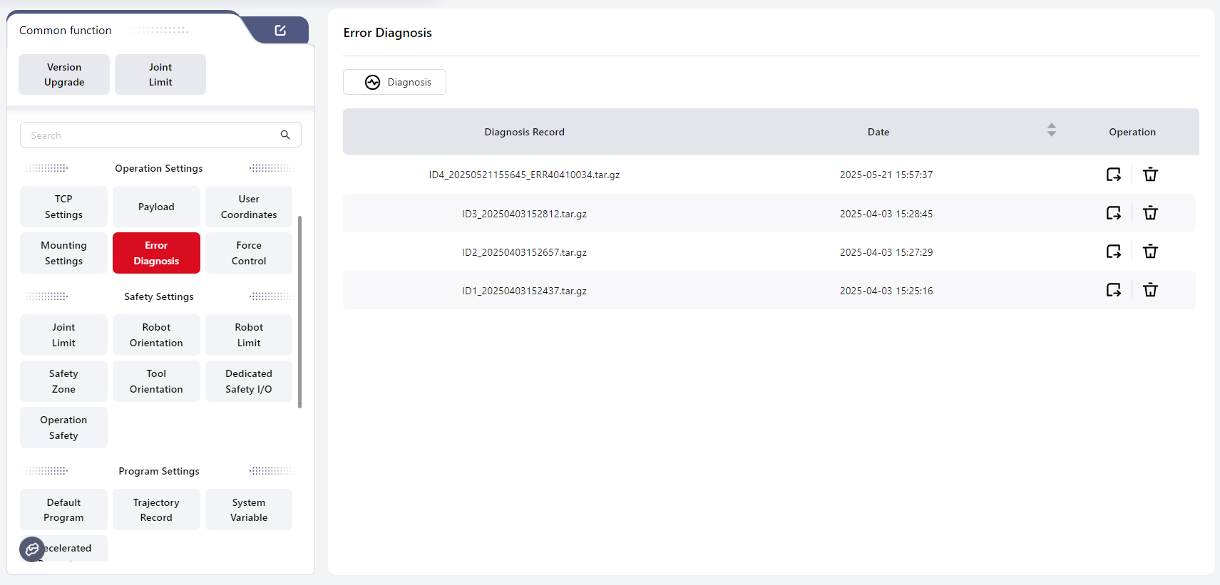
Users can also manually click Diagnose to export fault files and analyze the robot’s motion status:
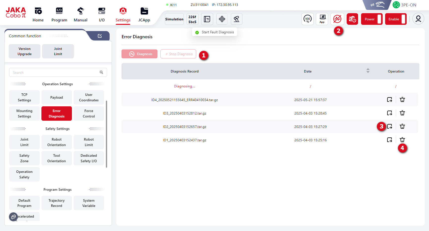
- 1 and 2: Stop diagnosis
- 3: Download the error file to the local device
- 4: Delete the selected error file
Force Control Configuration
Sensor Configuration
Users can configure force control–related functions on this page.
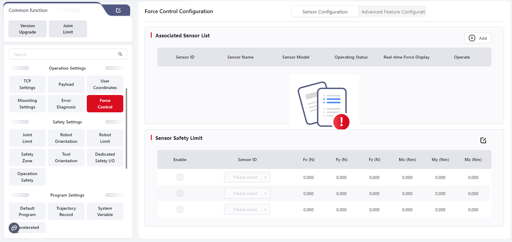
Click Add under the Associated Sensor List to add a new sensor:
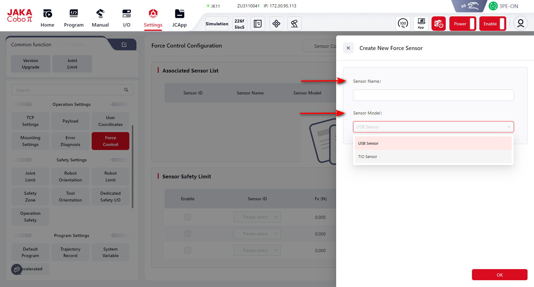
Enter the Sensor Name and select the Sensor Model.
After clicking Confirm, the new sensor will appear in the Associated Sensor List:
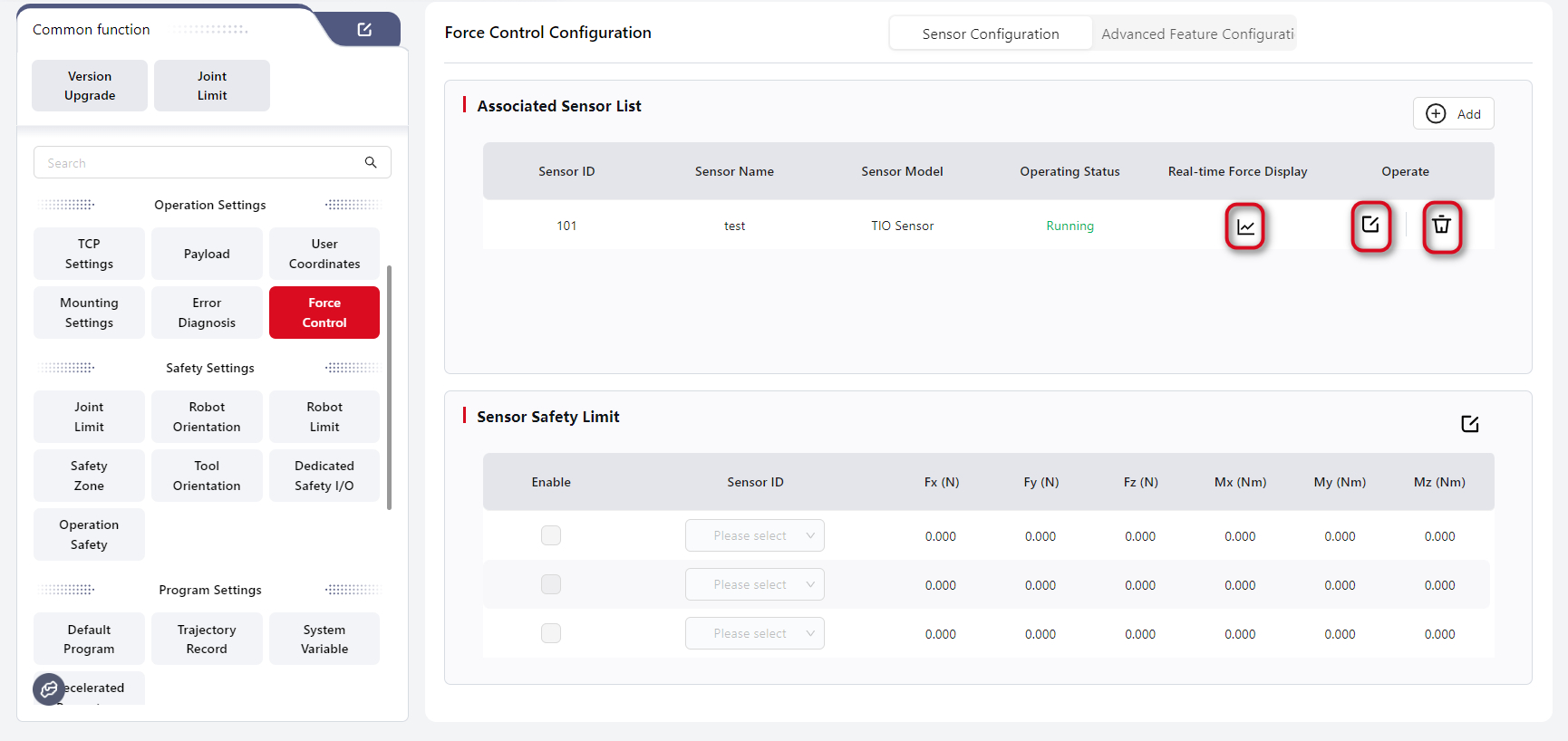
You can click Real-time Force Display to view the current force data of the sensor, or click the Edit icon to modify the configuration:
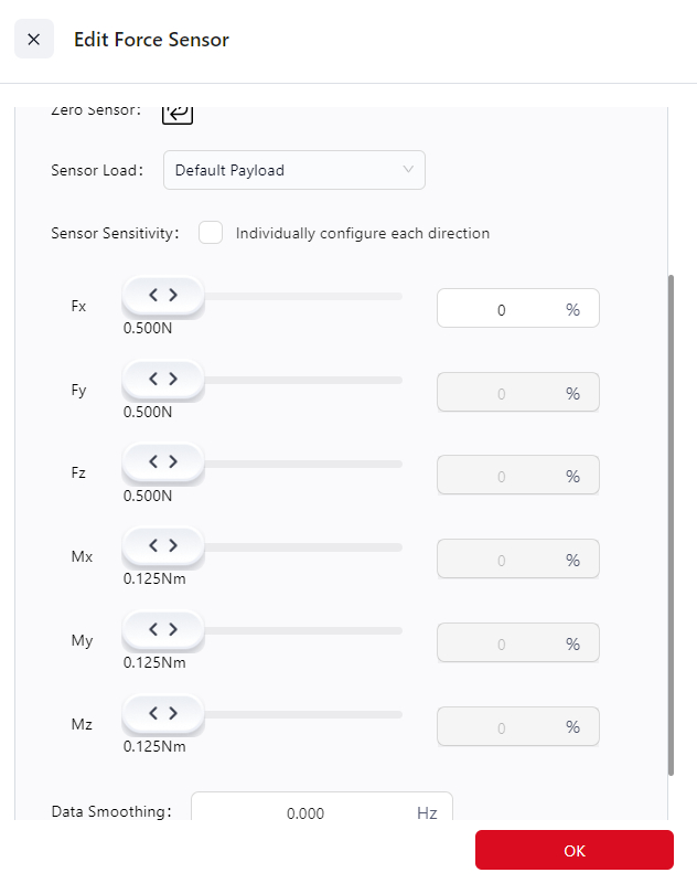
- Zero Sensor: Click this button to zero the sensor. During zeroing, ensure that the robot end has no external contact forces, and that the robot is not in Tool Drag or Constant Force Compliance Mode. It is recommended to perform sensor zeroing before each use to ensure measurement accuracy. Zeroing can also be done from the real-time force display interface.
- Sensor Load: The sensor load refers to the load directly mounted on the sensor. For S Series robots, this load does not need to be configured and defaults to the same value as the robot body load. For other external sensors:
- If the sensor is directly mounted on the robot flange, this load should match the robot load.
- If the sensor is not mounted directly on the flange, the sensor load may differ and should be created as a new load entry in the Load Management page, then selected here.
- Sensor Sensitivity: This defines the minimum external force and torque the sensor can detect. Only when the absolute value of the sensor reading exceeds this threshold is it considered to be under force; the amount exceeding the threshold is treated as the actual measured force. If the reading is below the threshold, it is treated as no force detected.
- A lower sensitivity value makes the robot easier to drag in Tool Drag mode, makes Maximum Force Limit and Force Control Stop Conditions more sensitive, and reduces target force error in Constant Force Compliance mode.
- When Configure Independently for Each Direction is checked, sensitivities for individual axes can be adjusted separately. Otherwise, only the Fx direction can be modified, and other axes will automatically follow.
- Data Smoothing: Filters out signals above a certain frequency to smooth the force curve.
- A value of 0 disables data smoothing.
- Smaller values result in stronger filtering and smoother force curves, but too small a value reduces responsiveness to force changes.
- Recommended range: 20–60 Hz.
- Typically used in operations like polishing, where external vibrations cause force fluctuations.
Warning
- Sensor zeroing takes about 1 second. During this time, no external forces other than the tool’s own gravity should be applied below the black rubber ring of the robot flange (including contact, collision, or pressing). Otherwise, it may cause compensation errors, leading to uncontrolled robot motion, equipment damage, or personal injury.
- After equipment installation, robot restart, fault recovery, or long-term sensor power-on, you must perform sensor zeroing before using any force control function, otherwise uncontrolled motion may occur, leading to equipment damage or injury.
Note
- Due to factory offsets and temperature variations, a sensor may show non-zero readings even when no external forces are applied. A deviation within 20 N or 2 Nm is normal and does not indicate a defect. Simply perform zeroing to restore accuracy. If the sensor shows readings above 20 N or 2 Nm with no load attached, contact JAKA technical support team.
- As a precision device, the sensor may experience minor zero drift due to environmental factors such as temperature or robot posture changes. Even after correct zeroing, a small drift within 0.5% of full scale (≈1–2 N) may appear. Adjust sensor sensitivity appropriately to compensate for this behavior.
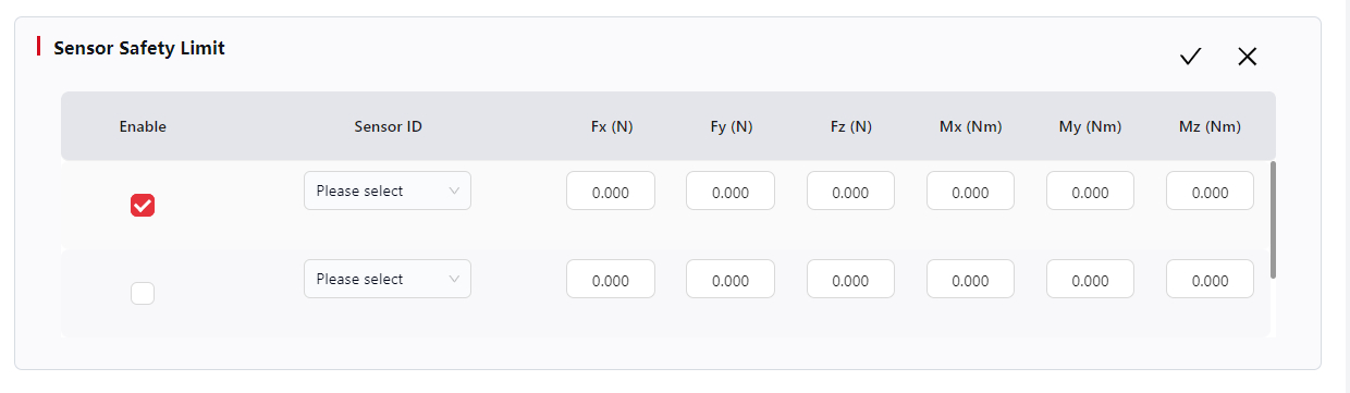
Click the Edit icon next to Sensor Safety Limit to configure the maximum force (Fx, Fy, Fz) and maximum torque (Mx, My, Mz) each sensor can withstand. After editing, check Enable — if the detected force exceeds the set maximum limit, the robot will stop immediately and display a collision alarm.
- When the sensor is not zeroed, the safety limits are inactive.
- If a safety limit is set to 0, the default value (the sensor’s maximum range) will be used.
- For details on sensor ranges, refer to the JAKA S Series Hardware User Manual.
Advanced Feature Configuration
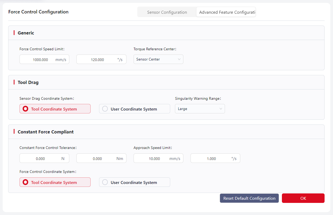
- Force Control Speed Limit:
- In Tool Drag Mode, limits the TCP speed during manual dragging.
- In Constant Force Compliance Mode, limits the maximum difference between the commanded and actual TCP speeds.
- Default: 500 mm/s, 60°/s.
- Torque Reference Center:
- Defines the reference point for torque calculation caused by external forces.
- The distance between the actual force application point and this reference determines the torque arm, which affects rotation direction, speed, stop conditions, and torque limits in force control.
- Options: Sensor Center or TCP (default: Sensor Center).
- Sensor Drag Coordinate System:
- The coordinate system used in Tool Drag Mode.
- Singularity Warning Range:
- Defines how close the robot can get to a singularity before a warning is triggered in Tool Drag Mode.
- A larger value triggers warnings farther from singularities. Default: Medium.
- Constant Force Control Tolerance:
- Maximum allowable difference between the actual contact force and the target force.
- When within this range, the robot considers the target force reached and stops adjusting.
- Default: 0.
- Approach Speed Limit:
- In Constant Force Compliance Mode, limits the maximum difference between actual and commanded TCP speeds before the sensor force exceeds the sensitivity threshold.
- Default: 10 mm/s, 1°/s.
- Force Control Coordinate System:
- The reference coordinate system used by all force control functions except Tool Drag Mode.
Safety Settings
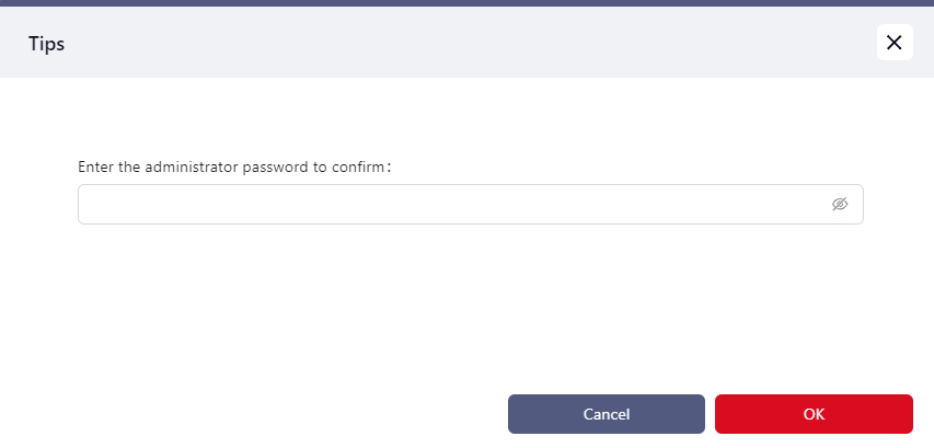
Warning
To ensure operational safety, important safety parameter settings and critical user data configurations require entering the administrator password for secondary confirmation.
Joint Limits
In this interface, users can configure the soft limit angle, speed limit, and error alarm threshold for each joint.
Tips
- The adjustable ranges for Positive Limit, Negative Limit, and Speed Limit are restricted to the default range displayed on the interface.
- The Error Threshold determines the deviation limit. When the motion deviation exceeds this threshold (default 80%), the system will trigger an alarm.
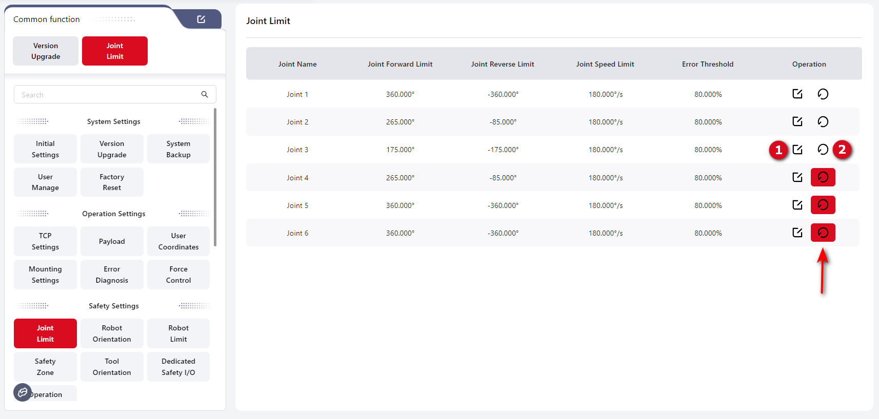
1: Set the value.2: Reset to default.
Tip
If a joint limit has been modified from its default value, the reset button will turn red (as shown by the arrow).
Robot Orientation
This interface allows users to set the robot’s Default Orientation, Open Orientation, and Safe Orientation:
Tips
- Default Orientation: The packing pose of the robot.
- Open Orientation: The reference zero position used for joint mechanical calibration.
- Safe Orientation: User-defined. One Safe Orientation can be set as the initial orientation. When pressing the Home button on the teach pendant, the robot will move to this orientation. Once the robot reaches the initial orientation, a digital output (DO) signal for “Home Position” can be triggered.
- Safe Orientation Tolerance: User-configurable, range 0.001–3. When all joint angles are within this deviation range from the defined Safe Orientation, the DO signal bound to “Safe Orientation” will be triggered.
- Speed: The movement speed when the robot moves to the target pose. Default: 30%.
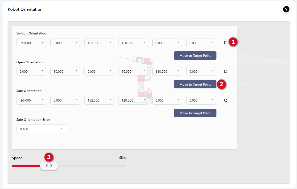
1: Modify value.2: Move to target pose.3: Set speed.
Robot Limit
Collision Settings
Users can configure the robot’s collision protection sensitivity on this page.
- Quick Setting Choose a sensitivity level to quickly configure collision protection. The higher the selected level, the less likely the robot will trigger a collision alarm during motion.
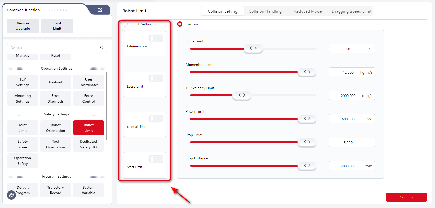
- Custom Users can manually adjust detailed parameters to fine-tune collision protection sensitivity.
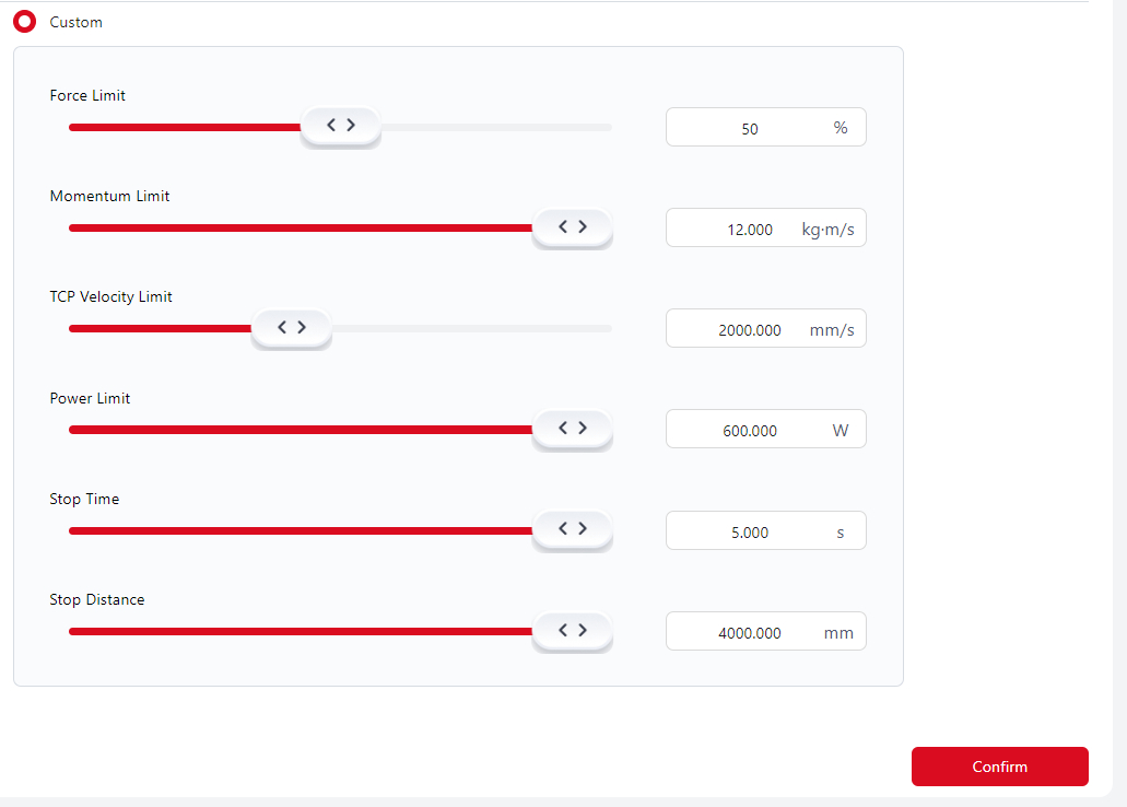
Explanation
- Force Limit: The amount of external force required to trigger a collision alarm. A higher percentage means a greater force is needed before the robot stops.
- Momentum Limit, TCP Velocity Limit, Power Limit, Stop Time, and Stop Distance affect the robot’s overall motion speed. Lower values result in slower robot movements.
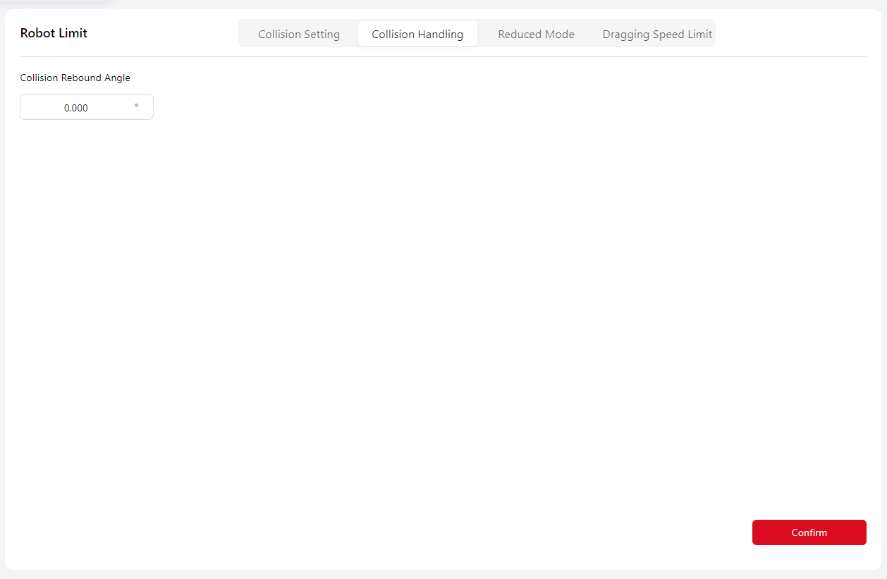
Collision Response Settings
Users can set the rebound angle of the robot after a collision, ranging from 0–3°. If set to 0°, the robot will not rebound after a collision.
During program execution:
- For minor collisions (joint position deviation ≈ 1°), the robot stops motion and terminates the program.
- For severe collisions (joint position deviation ≥ 3.6°), the robot stops motion and disables servo power.
In manual mode, regardless of the rebound angle setting, the robot will not rebound after a collision. If an external force continues to be applied, the user may still move the robot slightly within a limited range.
Reduced Mode Settings
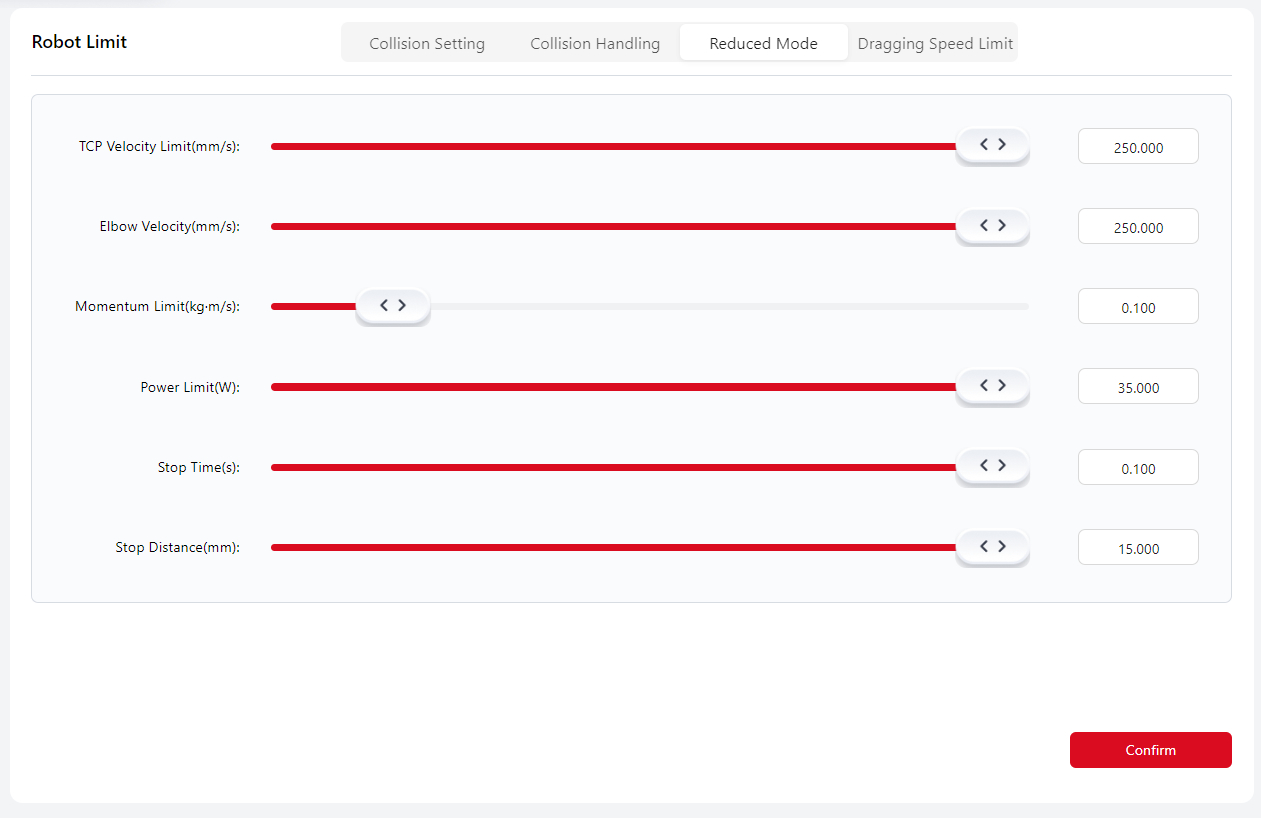
This interface allows users to configure various limitation parameters for the robot in Reduced Mode.
You can set parameters by dragging the sliders or entering numerical values directly. The maximum configurable range depends on the connected robot model.
After clicking Confirm, the system will prompt: “Safety verification parameters have changed.”
Dragging Speed Limit
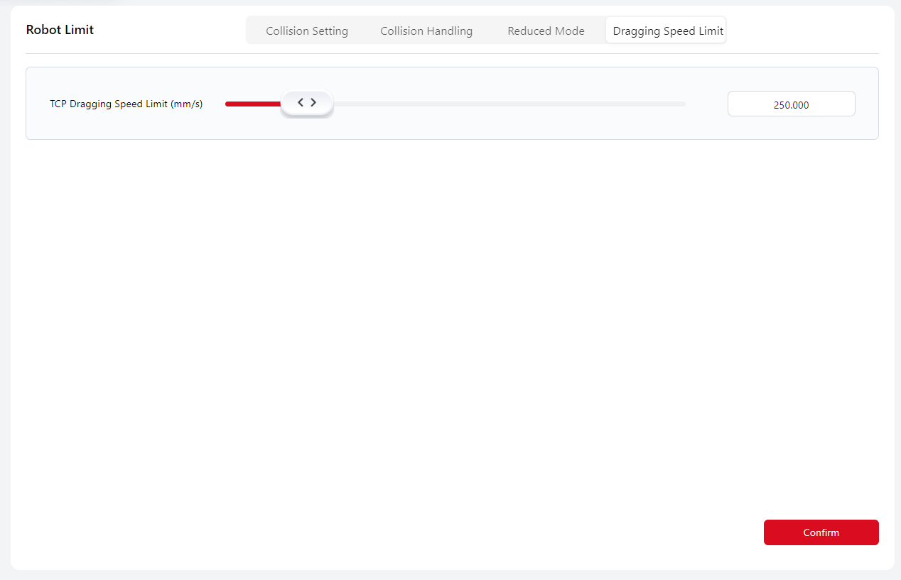
Users can configure the TCP dragging speed limit here, adjustable within 50–1500 mm/s.
This setting only affects the robot’s TCP speed in Drag Mode. If the drag speed exceeds this limit, the robot will stop motion, remain powered, and exit Drag Mode.
Safety Zone
To prevent collisions between the robot and surrounding objects during operation, users can define Safety Planes and Safety Cubes to restrict the motion range of the robot’s TCP or elbow joint (Joint 3).
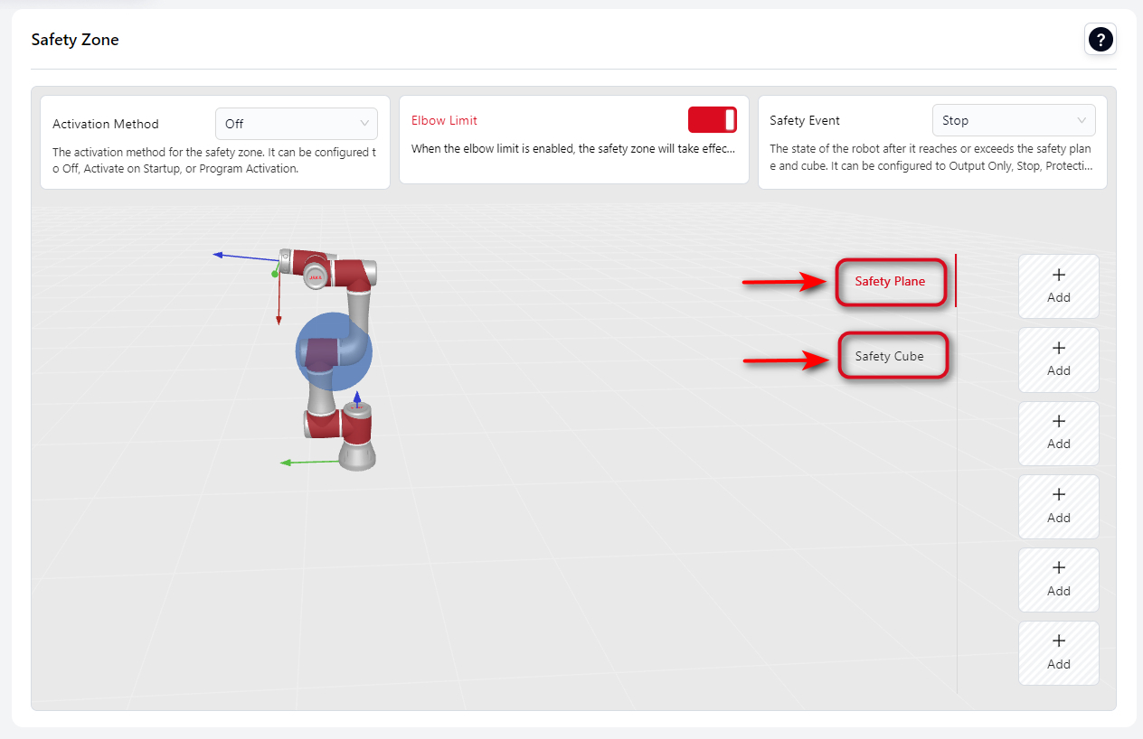
Before configuring individual safety planes or cubes, the following general parameters should be set first, as they apply to all safety zones.
- Activation Mode
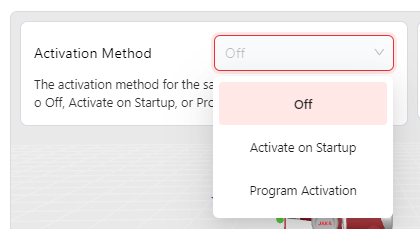
Off: Safety zones are disabled.
Activate on Startup: Safety zones become active after robot boot-up.
Program Activation: Safety zones are active only when the robot is running a program. They are inactive during drag, manual operation, or SDK control.
Elbow Limit
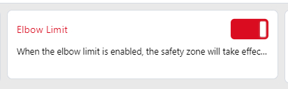
When enabled, the defined safety planes also apply to the elbow joint area (Joint 3). The effective range is represented as a sphere surrounding the elbow.
- Safety Event
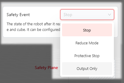
- Stop: When the robot enters the danger zone or attempts to move deeper into it, motion stops, the program terminates, and servo power is disabled.
- Reduce Mode: When the robot enters the danger zone, it switches to Reduced Mode using the parameters defined under “Reduced Mode Settings.” It exits Reduced Mode once it returns to the safe zone.
- Protective Stop: When the robot moves from the safe zone into the danger zone, it triggers a Protective Stop. The robot can resume motion into the danger zone after the user confirms by clicking “OK” or by activating the Protective Stop Reset Input (safety DI).
- Output Only: When a safety plane or cube is triggered, the corresponding DO signal is activated.
Please note:
When the robot is in Protective Stop mode and the system is set to Manual Mode, the operator may, in a safe environment, press and hold the three-position enable switch on the teach pendant in position 2.
While the switch is held in this position, the operator can move the robot by hand, perform manual control, or execute programs in Manual Mode.
Warning:
The operator must remain attentive and exercise caution throughout this procedure.
If any unsafe situation occurs, the operator must immediately release the three-position enable switch, and the robot will stop again.
Configuring a Safety Plane
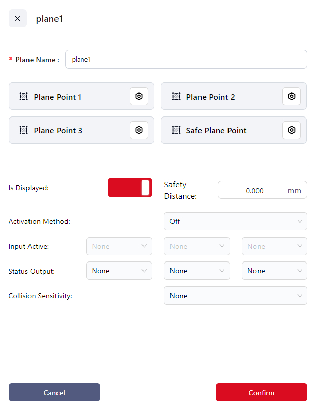
- Click
+Addto enter the setup page. - Enter the plane name in
Plane Name. - Click the icons next to
Plane Point 1, 2, 3to enter the manual operation interface and set the positions of the three plane points. The controller calculates the position of the safety plane based on these points and displays it in the 3D model area. - Click the icon next to
Safe Plane Pointto enter the manual operation interface. You can designate one side of the safety plane as the safe side and then move the robot to that side. Click "Confirm" once done. The side where the end effector's origin is located is considered the safe side. - Set the
Safe Distancewhich is the distance (in mm) between the robot's end effector and the safety plane. When the actual distance between the robot's end effector and the safety plane is less than this value, the safety plane is triggered, and the robot's motion state will change. - Choose the
Activation:
- Off: Do not enable the current safety plane.
- Activate: Enable the current safety plane.
- Input Activate: Bind the current safety plane to a DI. When this DI receives an input signal, the safety plane is activated.
- If you choose "Input Activate", you can select the DI to bind this safety plane from the dropdown in the
Input Activationfield.
Tips
A single DI can be bound to multiple safety planes and safety cuboids simultaneously.
- If you choose "Input Activate", you can select the DI to bind this safety plane from the dropdown in the
- If you want to visually check if the safety plane is triggered, you can bind it to a DO:
- From the dropdown in
Status Outputselect the DO to bind the safety plane. Once triggered, the DO's status in the I/O panel will show as "ON".Tips
A DO can only be bound to one safety plane or safety cube
- Set the
Collision SensitivityIf collision sensitivity is configured, when the robot enters a danger zone, the collision level switches to the level defined in the safety zone. When the robot returns to the safe zone, the collision level reverts to the one set in the "Motion Limit" settings. If the robot enters multiple safety zones with defined danger zones, the collision level switches to the most sensitive setting. The lower the number, the higher the sensitivity (LV1 > LV2). - Click
Confirmto save this safety plane.
Configuring a Safety Cube
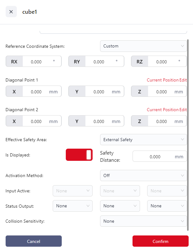
- Click
+Addto enter the setup page. - Enter a name for the cube in the
Cube Namefield. - Set the
Reference Coordinate System:- Can be set to the world coordinate system, a configured user coordinate system, or custom.
- If
Customizeis chosen, you must enter the rotation angles of the custom coordinate system relative to the world coordinate system in the RX, RY, and RZ fields.
Tips
If the position of the selected user coordinate system is modified in the "User Coordinate System" interface, the reference coordinate system will automatically change to custom, with the RX, RY, and RZ values being those before the user coordinate system was modified.
- Set the
Vertex 1andVertex 2,which will be used by the controller to calculate the cube. The positions of the diagonal points are relative to the reference coordinate system. You can:- Directly enter the distances of the diagonal points from the origin of the reference coordinate system in the X, Y, and Z fields.
- Click
Editto jog or drag the robot to the target point. When dragging the robot, the diagonal point is the center of the robot’s end effector flange.
- Set the
Effective Safety Area:- Internal Safety: The inside of the cube is the safety area.
- External Safety: The outside of the cube is the safety area.
- Set the
Safe Distance:This is the distance between the robot’s end effector and the safety area, in millimeters. When the robot’s end effector is closer than this value to the safety area, the safety cube will be triggered, and the robot’s movement state will change. - Choose the
Activation:
- Off: Does not enable the current safety cube.
- Activate: Enable the current safety cube.
- Input Activate: Bind the current safety plane to a DI. When this DI receives an input signal, the safety cube is activated.
- If you choose "Input Activate", you can select the DI to bind this safety plane from the dropdown in the
Input Activatefield.
Tips
A single DI can be bound to multiple safety planes and safety cubes.
- If you choose "Input Activate", you can select the DI to bind this safety plane from the dropdown in the
- To visually check if the current safety cube has been triggered, you can bind it to a DO:
- In the
Status Outputdropdown, choose the DO you want to bind to the safety cube. When the safety cube is triggered, the status of this DO will be "ON" in the I/O panel.Tips
A DO can only be bound to one safety plane or safety cube.
- Set the
Collision SensitivityIf collision sensitivity is configured, when the robot enters a danger zone, the collision level switches to the level defined in the safety zone. When the robot returns to the safe zone, the collision level reverts to the one set in the "Motion Limit" settings. If the robot enters multiple safety zones with defined danger zones, the collision level switches to the most sensitive setting. The lower the number, the higher the sensitivity (LV1 > LV2). - Click
Confirmto save the safety cube.
Tool Orientation
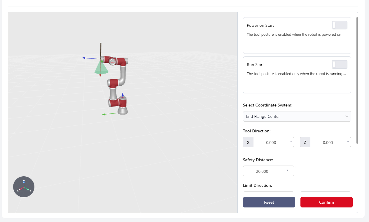
In this interface, users can set the tool orientation, defining a conical range to limit the movement of the robot's end effector within this range to avoid interference between the end effector and the robot body or external environment.
Conical Range Diagram:
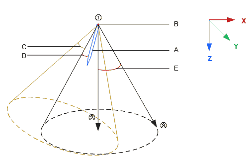
- A:End effector tool
- B:Selected coordinate system origin
- C:Tool direction offset angle, X-axis offset
- D:Safe distance
- E:Limitation range
Robot Power On:
The tool orientation limitation is active immediately after the robot powers on.
Run Start:
Enable During Operation: The tool orientation limitation is only active during program execution. It is not active during drag or manual operation modes.
Select Coordinate System:
Determines the location of the end effector and the vertex of the cone. The coordinate system origin is the vertex.
Tool Direction:
Determines the direction of the end effector, based on the X-axis or Z-axis offset angle of the selected coordinate system.
Safety Distance:
The distance between the end effector and the defined tool boundary, ranging from 0 to the set value. When the distance is less than the safe distance, a popup will warn "Approaching Orientation Safety Limit." If the end effector reaches the boundary, the robot will stop, disable itself, and display "Exceeded Orientation Limit - Protective Stop."
Limit Direction:
Defines the location and size of the tool boundary.
- Method 1:Enter RX, RY, RZ angles directly.
- Method 2: Click Settings to enter the tool limit interface. Click the settings icon again to enter the manual operation page and determine the positions of Points 1, 2, and 3. The controller will calculate the
X Y Zvalues based on these points.
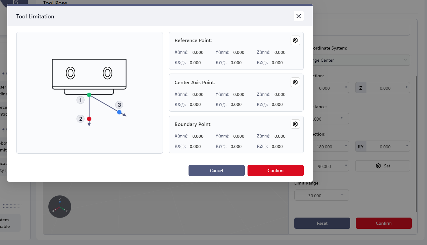
Limit Range:
Refers to the angle between the cone's centerline and its boundary, with a configurable range of 5° to 180°.
Note:
When the robot is in motion, the cone translates along the world coordinate system based on the robot's movement direction.
Dedicated Safety I/O
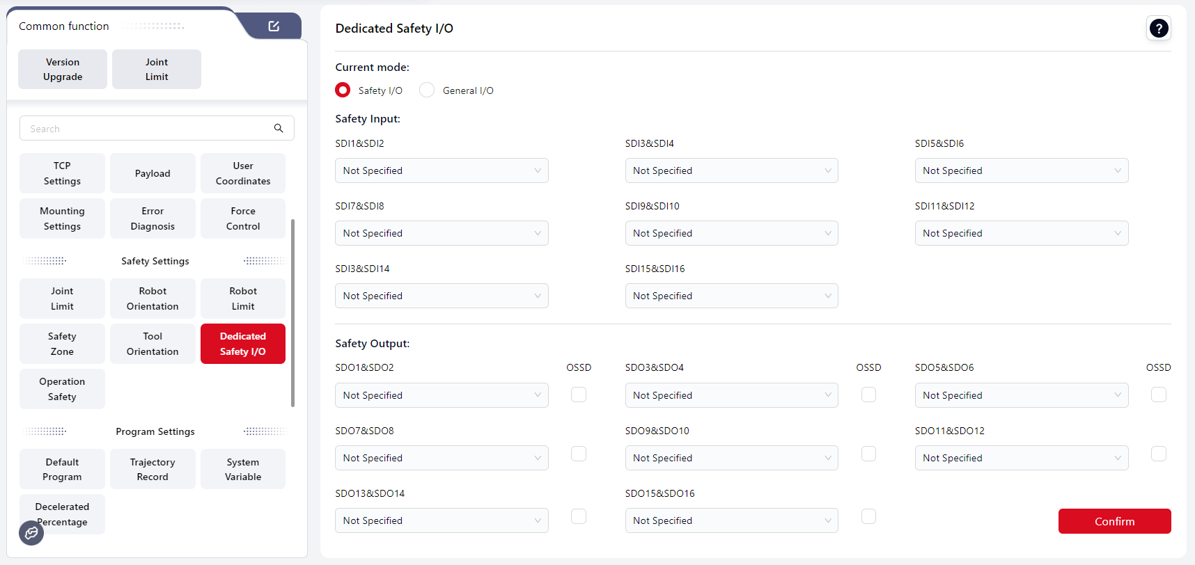
Users can configure the control cabinet panel's physical I/O to bind safety signals, turning the control cabinet's I/O into dedicated safety I/O signals to control the robot's safety actions and monitor its safety status. These dedicated safety I/O signals operate as dual-loop signals.
The standard cabinet has eight reusable safety I/O channels. All safety DI (Digital Input) channels can be configured with the same function, and all safety DO (Digital Output) channels can also be configured with the same function. The specific functions are described below:
| Name | Function | I/O Type |
|---|---|---|
| Additional Emergency Stop Input | When this input is low, the robot performs an emergency stop. | Input |
| Additional Safety Guard Stop Input | When this input is low, the robot performs a protective stop. | Input |
| Safety Guard Stop Reset Input | When the input signal changes from low to high, a protective stop reset is executed. | Input |
| Reduced Mode Input | When this input is low, the robot enters reduced mode. | Input |
| Three-Position Enable Input | This input works with a three-position switch. When in positions 1 or 3, low level, the robot performs three-position enablement restrictions. When in position 2, high level, the restriction is canceled. | Input |
| Collision Detection Off | When enabled, a rising edge signal on this input disables collision detection for the robot. | Input |
| Set Collision Sensitivity Level 1 | When enabled, a rising edge signal on this input sets the robot's collision sensitivity level to LV1. The lower the value, the higher the sensitivity. When multiple levels are triggered, the stricter level takes precedence. | Input |
| Set Collision Sensitivity Level 2 | When enabled, a rising edge signal on this input sets the robot's collision sensitivity level to LV2. The lower the value, the higher the sensitivity. When multiple levels are triggered, the stricter level takes precedence. | Input |
| Set Collision Sensitivity Level 3 | When enabled, a rising edge signal on this input sets the robot's collision sensitivity level to LV3. The lower the value, the higher the sensitivity. When multiple levels are triggered, the stricter level takes precedence. | Input |
| Set Collision Sensitivity Level 4 | When enabled, a rising edge signal on this input sets the robot's collision sensitivity level to LV4. The lower the value, the higher the sensitivity. When multiple levels are triggered, the stricter level takes precedence. | Input |
| Set Collision Sensitivity Level 5 | When enabled, a rising edge signal on this input sets the robot's collision sensitivity level to LV5. The lower the value, the higher the sensitivity. When multiple levels are triggered, the stricter level takes precedence. | Input |
| Set Collision Sensitivity to Lowest | When enabled, a rising edge signal on this input sets the robot's collision sensitivity to the lowest level. | Input |
| Emergency Stop Button Status Output | Outputs low when the emergency stop on the handle is pressed. | Output |
| System Emergency Stop Status Output | Outputs low when the system is in an emergency stop state. | Output |
| System Protective Stop Status Output | Outputs low when the system is in a protective stop state. | Output |
| Motion Status Output | Outputs low when the robot is in motion. | Output |
| Non-Stopping Status Output | Outputs high when the robot is stopped or stopping due to an emergency stop or protective stop. | Output |
| Reduced Mode Status Output | Outputs low when the robot is in reduced mode. | Output |
| Non-Reduced Mode Status Output | Outputs low when the robot is not in reduced mode. | Output |
| Collision Detection Off Output | Outputs low when collision detection is disabled. The output state is updated in real-time only after the robot is enabled. | Output |
| Collision Sensitivity Level 1 Output | Outputs low when the robot's collision sensitivity is set to LV1. The output state is updated in real-time only after the robot is enabled. | Output |
| Collision Sensitivity Level 2 Output | Outputs low when the robot's collision sensitivity is set to LV2. The output state is updated in real-time only after the robot is enabled. | Output |
| Collision Sensitivity Level 3 Output | Outputs low when the robot's collision sensitivity is set to LV3. The output state is updated in real-time only after the robot is enabled. | Output |
| Collision Sensitivity Level 4 Output | Outputs low when the robot's collision sensitivity is set to LV4. The output state is updated in real-time only after the robot is enabled. | Output |
| Collision Sensitivity Level 5 Output | Outputs low when the robot's collision sensitivity is set to LV5. The output state is updated in real-time only after the robot is enabled. | Output |
| Collision Sensitivity to Lowest Output | Outputs low when the robot's collision sensitivity is set to the lowest level. The output state is updated in real-time only after the robot is enabled. | Output |
Safety DI Signal Redundancy:
All eight channels of the safety digital input signals are redundant equivalent input signals.
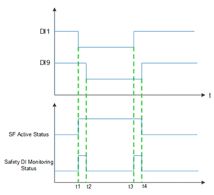
If one of the safety signals (e.g., DI1 and DI9) is low, the safety function is activated (t1). The signal used to activate the safety function must be stable; otherwise, the robot will stop, requiring a restart.
When the safety function is turned off, the robot exits the safety state, and DI1 and DI9 must both transition from low to high (rising edge) within the signal tolerance time. If there is a discrepancy between DI1 and DI9 signals, and the discrepancy lasts longer than the tolerance time of 1 second (e.g., t2-t1 or t4-t3), the SCB (Safety Control Board) will determine that a fault has occurred with the safety DI, triggering the Safety DI Fault Rollback Function.
After repair, the robot must be re-powered to clear the safety DI fault. If the fault is not cleared, the robot cannot be powered on.
Safety DI Fault Rollback Function:
- The robot decelerates to stop, powers off, and program paused.
- The faulty DI channels are processed by substituting a low-level signal for the actual input signal. This fault state persists until the robot is re-powered and the error is confirmed to be cleared.
- The interface prompts that a safety DI error has occurred. After the fault is repaired, the robot must be restarted to exit the error state.
OSSD Description
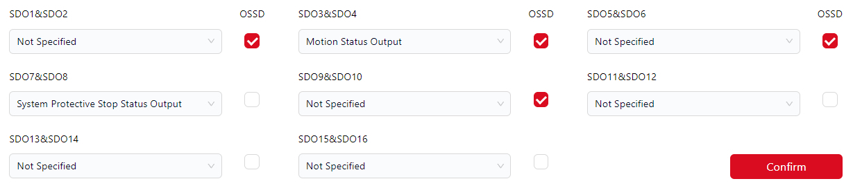
OSSD (Output Signal Switching Device) output is a type of signal-switching device used to control the on/off state of safety circuit outputs. It is commonly applied in machinery and equipment for protection and safety control.
When the safety output is inactive or high, the control cabinet can be configured to output an OSSD pulse. Users can enable this function by selecting the OSSD checkbox.
Once enabled, each individual channel generates a 1 ms low pulse every 64 ms on the safety output, with a 34 ms interval between the pulses of the two channels.
The safety system monitors when the output is connected to the power supply and will shut down the robot if necessary.
Switch Dedicated Safety I/O to General I/O
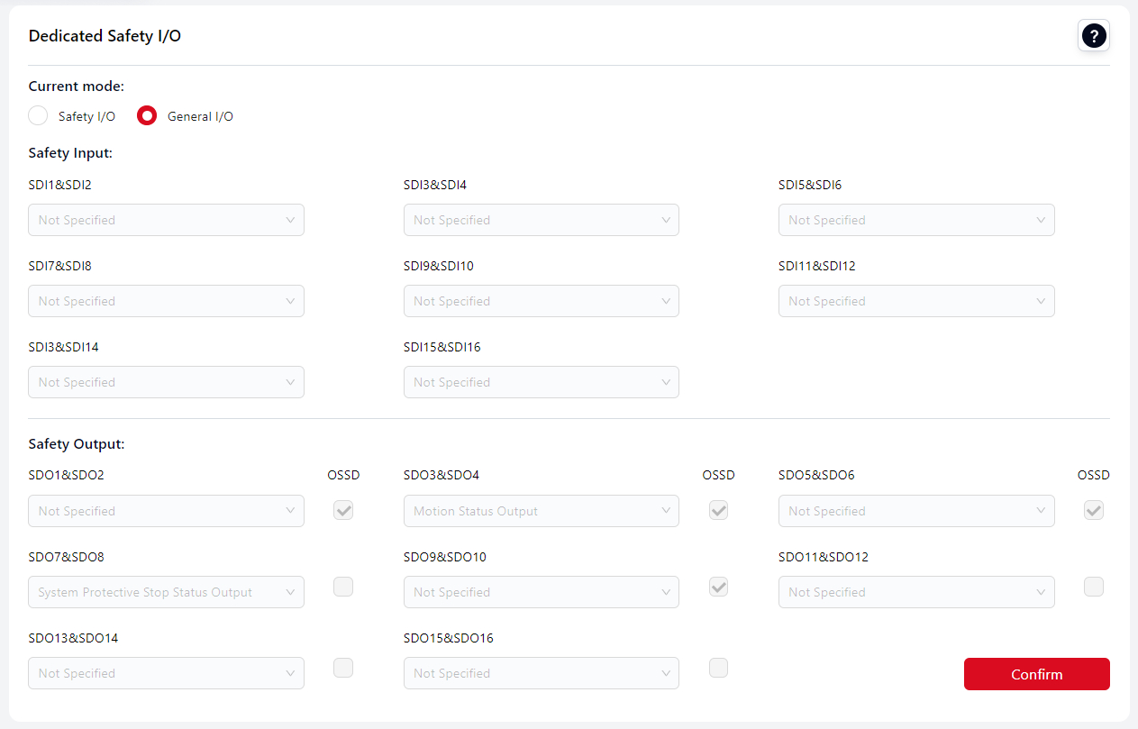
Users can switch the dedicated safety I/O to general I/O.
The general I/O functions can be customized by the user; however, they cannot be bound to the standard I/O functions of Coboπ. All other standard I/O operations remain supported.
After switching, enter the administrator password in the pop-up window to confirm the change.
Click Confirm again to apply the modification.
Once applied, the I/O status can be viewed in the I/O panel.
Tip
When switching from dedicated safety I/O mode to general I/O mode, the configurations made in the dedicated safety I/O mode will be retained.
Users can continue using them after switching back.
Vice versa.
Program Settings
Default Program
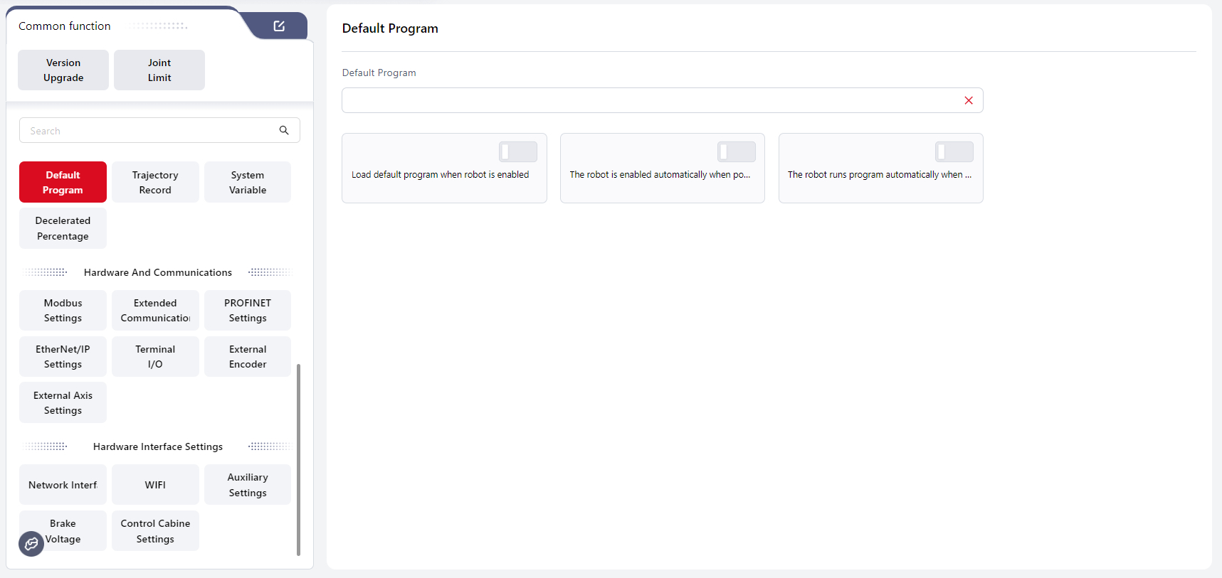
In this interface can set an existing program as the default program. Once set, the following options can be enabled to achieve specific functions:
Load Default Program when robot is enabled
When this switch is turned on, the default program is loaded automatically after the robot is enabled.
Warning:
If a default program is set, and both
Load Default Program when robot is enabled, and the signal to auto-run the program are triggered (e.g.,The robot runs program automatically when enabledis turned on), the Coboπ will run the default program.If a default program is set, and
Load Default Program when robot is enabled, is turned on, but no auto-run signal is triggered, the Coboπ will not run any program.If a default program is set, but
Load Default Program when robot is enabled, is not turned on, and an auto-run signal is triggered, the Coboπ will display an error popup.If no default program is set, but
Load Default Program when robot is enabled, is turned on, and an auto-run signal is triggered, the Coboπ will display an error popup.If a default program is set, and both
Load Default Program when robot is enabled, and an auto-run signal are triggered while another non-default program is open, the default program will be run.
The controller will check in the background whether there are unsaved changes in the currently open program. If there are unsaved changes, the programming interface will be gray, displaying the currently open program, and a popup will prompt "Unsaved Changes in Current Program, Please Confirm After Stopping the Program."
If all changes have been saved, it will directly switch to the default program.
The robot is enabled automatically when powered on
When this switch is turned on, the robot will automatically be enabled after powered on.
The robot runs program automatically when enabled
When this switch is turned on, the robot will automatically run the set default program or the currently open program after being enabled.
If no default program is set, the currently open program will be run;
If a default program is set and Load Default Program when robot is enabled is turned on, the default program will be run.
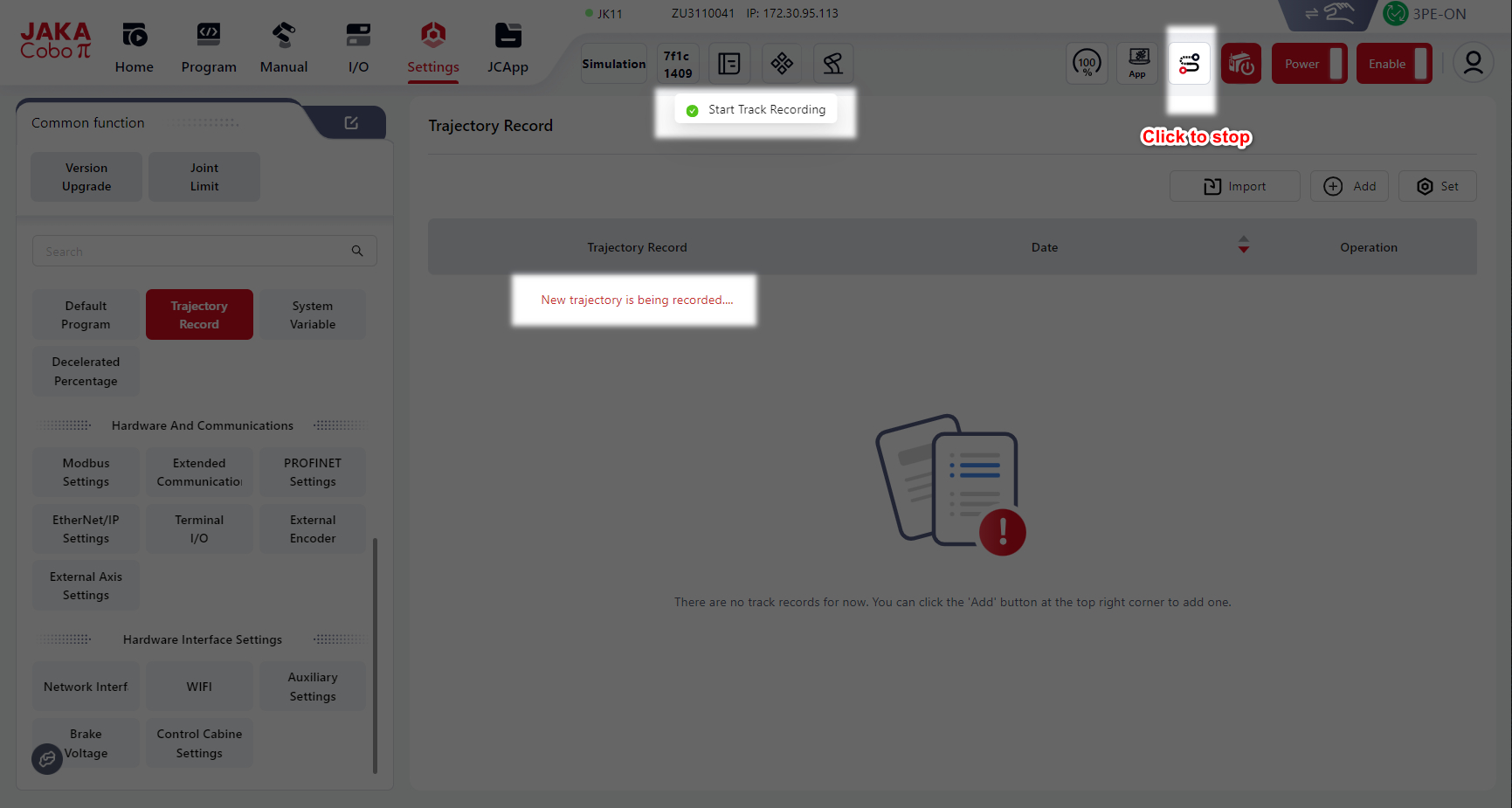
Trajectory Recording
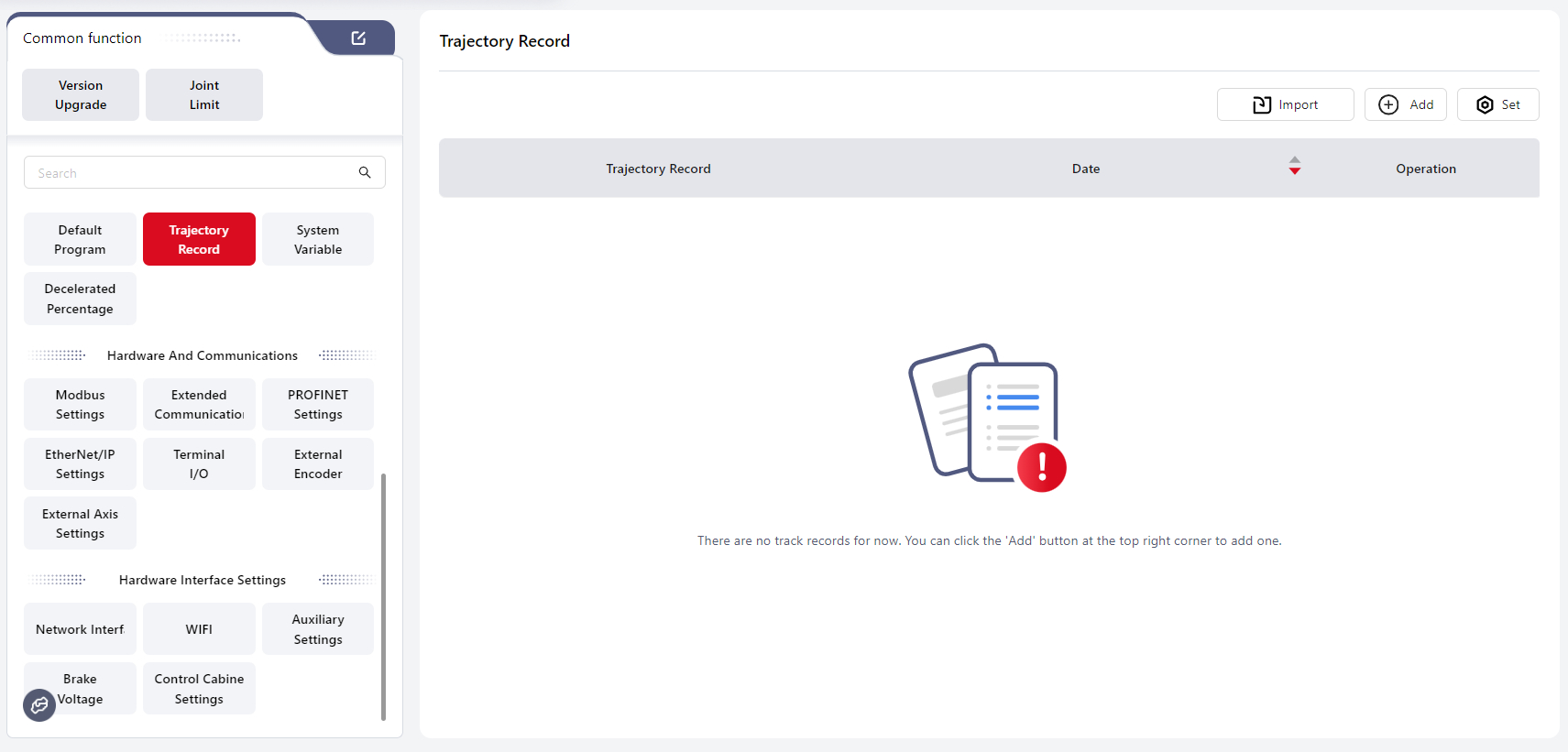
In this interface, the controller can record the robot’s motion path by dragging or manual operation and generate a trajectory file.
The current trajectory can also be recorded while the robot program is running.
During programming, the recorded trajectory file can be called using the Trajectory Recording command.
Operation steps:
- Click Settings to open the Trajectory Motion Editing interface.
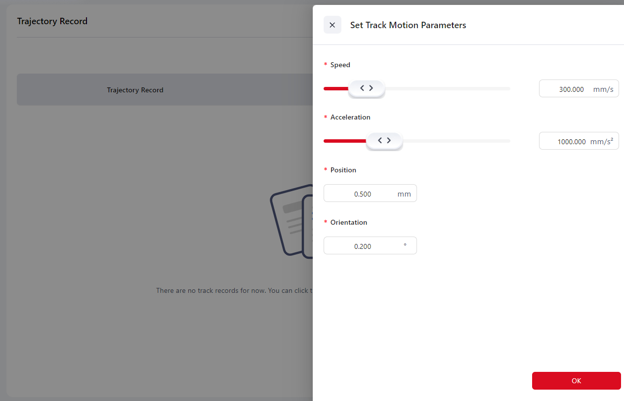
Tips
When the position or orientation change of the trajectory is smaller than Position/Orientation Accuracy × 10, the trajectory cannot be generated.
Therefore, if the motion distance of the trajectory is short, it is recommended to increase the position and orientation accuracy to 0.1.
Click Add, and a confirmation window will appear. Click Confirm. The page will indicate that trajectory recording is in progress.
Move the robot through drag mode or manual operation to perform the desired motion.
After finishing the teaching operation, click the S-shaped Trajectory Record button in the top navigation bar to stop recording. The trajectory file will be generated automatically.
- Click the icons to perform corresponding operations.
Tips
- The recorded trajectory can be replayed using the Trajectory Recording command in the programming control interface.
- Trajectory replay only records path information, not speed information.
- The same position will not be recorded repeatedly when the robot is stationary.
- If recording is not stopped manually, the recording will end automatically when it reaches 100,000 sampling points, and the trajectory file will be generated.
System Variables
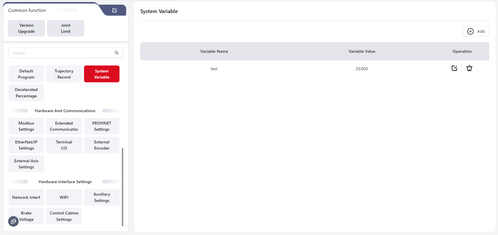
In this interface, users can create system variables that are available to all programs.
Tips
System variables are stored independently in the controller. They can only be numeric variables (range: -65535 to 65535) and can be accessed or modified in any program.
The variable values will not change or reset when a program starts or stops, or when the robot or control cabinet is powered off.
Operation steps:
- Click Add to open the Variable Editing interface.
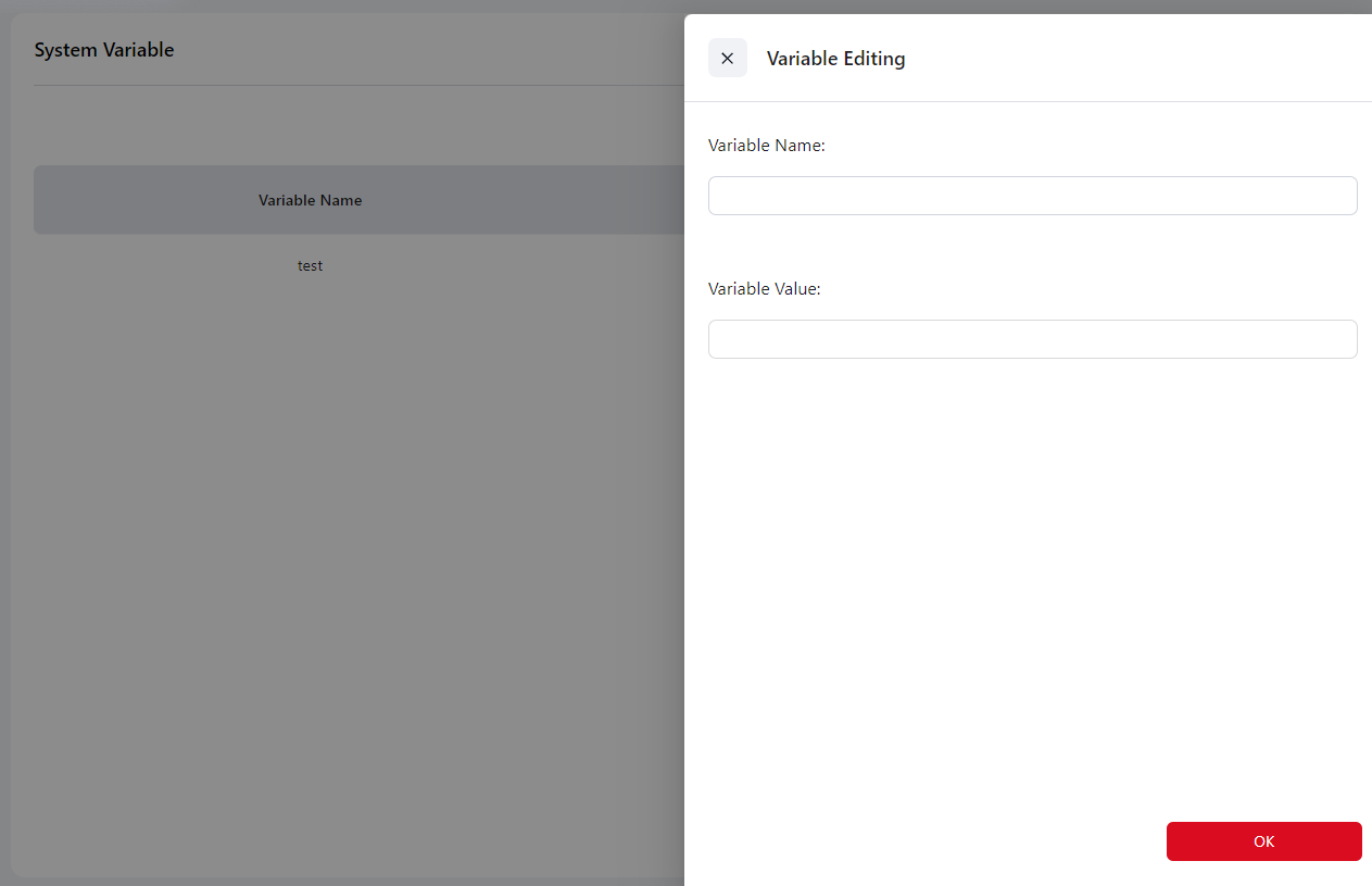
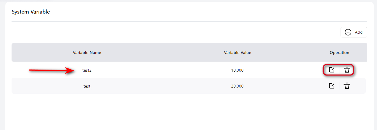
After editing, click Confirm. The newly created variable will be displayed on the interface.
Click the icon on the right of a variable to perform corresponding operations.
Tips
Up to 100 system variables can be stored.
System variables can also be created in the Variable Command Bar of the programming control interface.
Decelerated Percentage
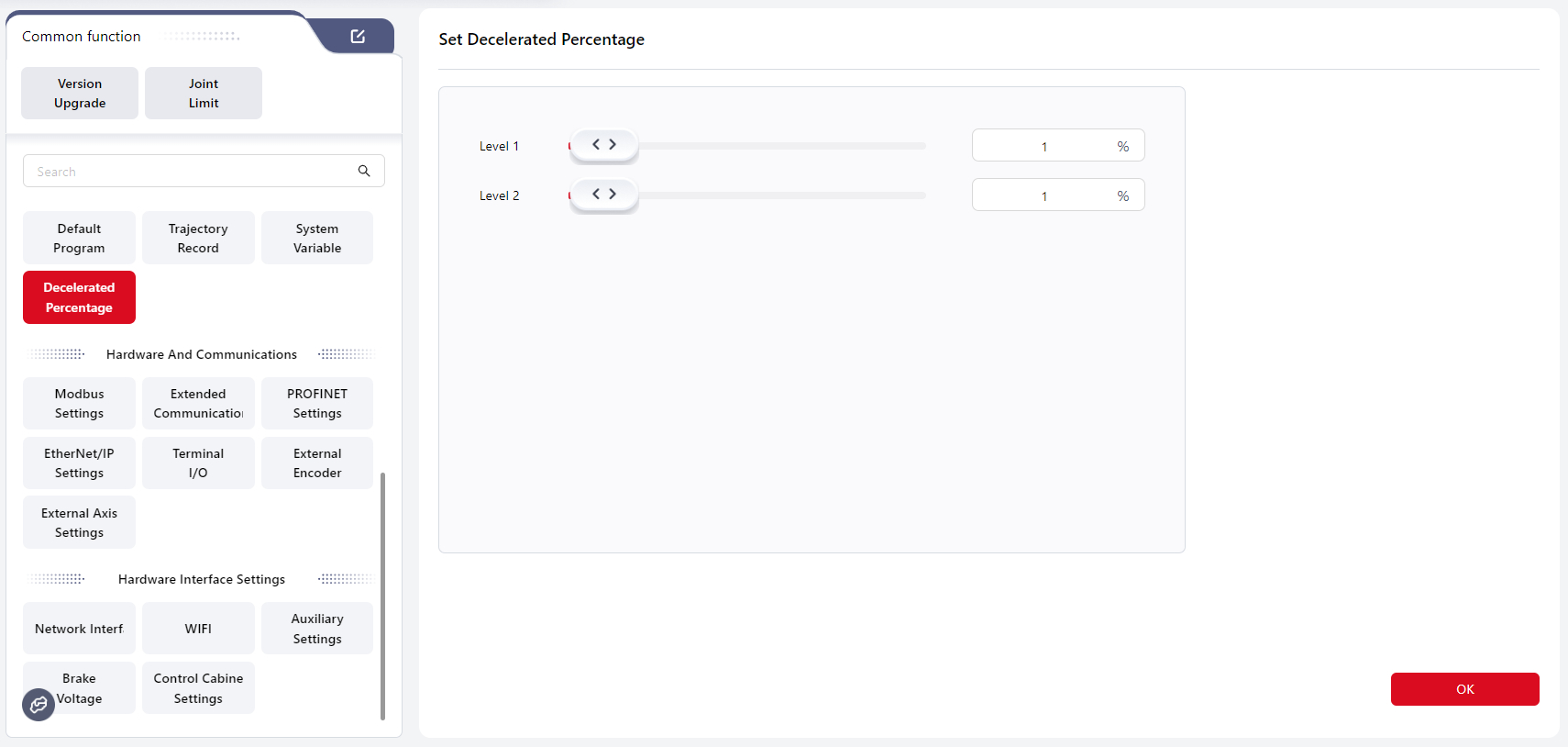
Speed scaling is used to adjust the robot’s motion speed when running a program. Users can configure it by dragging the slider or directly entering a value.
Once set and applied, the robot will move at the configured level speed during program execution.
For example, if Level 1 is set to 81% and triggered, the programming interface will display 81% speed, and the robot will move accordingly.
Warning
The Level 2 value must be less than the Level 1 value.
Tips
After configuration in this interface, the DI in the I/O Panel must be set to Level 1 or Level 2 mode to activate the scaling function.
If both Level 1 and Level 2 scaling are configured, Level 2 takes priority.
Decelerated percentage only takes effect during program execution. It does not apply in drag or JOG mode.
Hardware and Communication
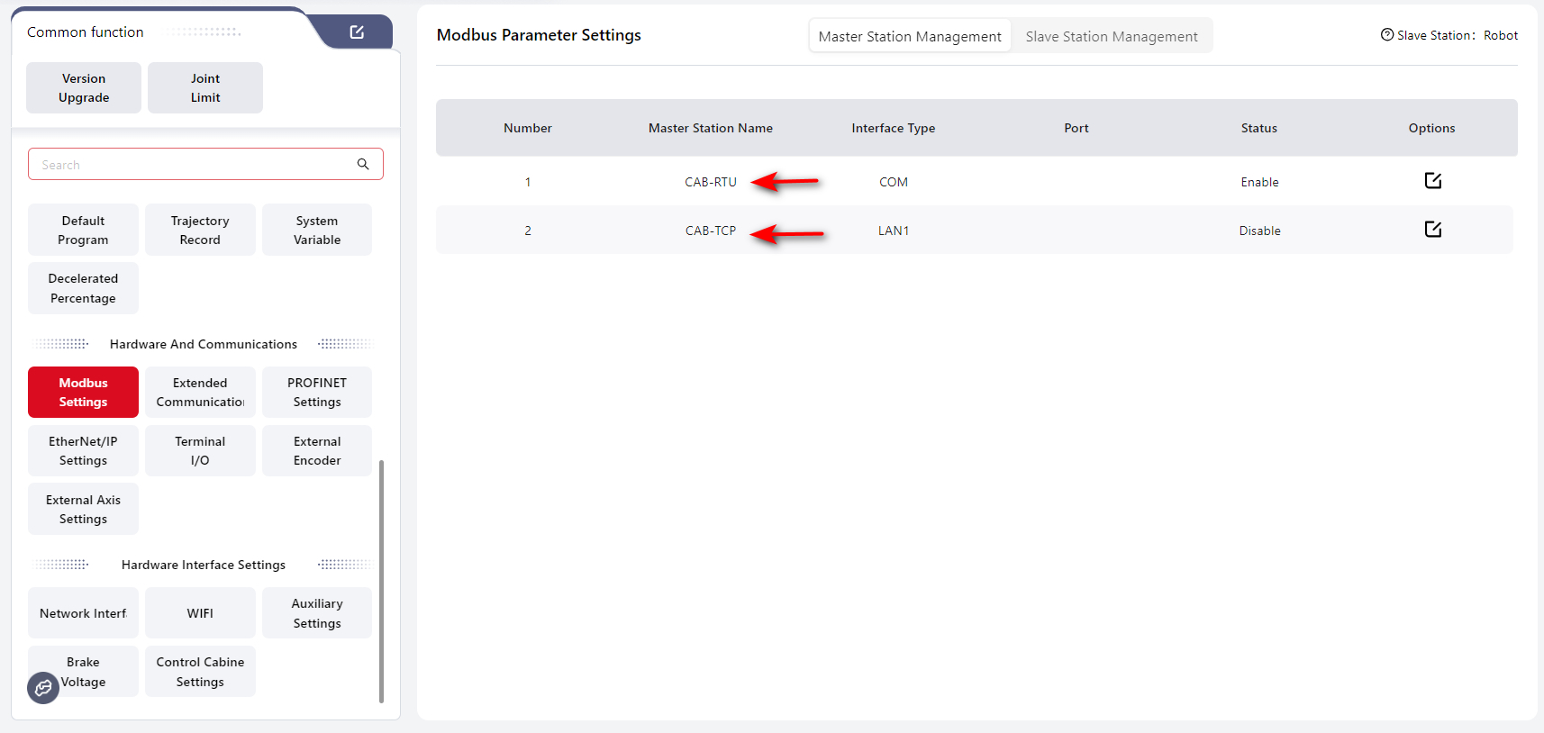
Modbus Settings
Coboπ supports both Modbus RTU and Modbus TCP/IP communication modes.
Master Station Management
In this mode, Modbus acts as the master, and the robot acts as the slave.
Warning
When configuring Modbus, make sure the robot is powered off and disabled.
Modbus RTU
Warning
This function requires customization.
Before use, connect the RS485 port on the front panel of the control cabinet.
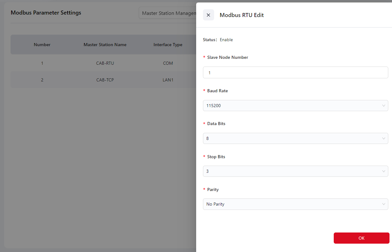
Operation steps:
- Click the Edit icon, then enter the slave node number and select baud rate, data bit, stop bit, and parity on the pop-up configuration page. Click Confirm.
- After configuration, power off the control cabinet, then restart and reconnect the robot to apply the settings.
- Once the connection with the master is established, write a program according to the Modbus Address Table (register addresses and function codes) to read the robot status or control robot I/O signals.
You can also view the status in I/O Panel → Modbus.
Modbus TCP/IP
Warning
Before use, connect the Ethernet port at the bottom of the control cabinet.
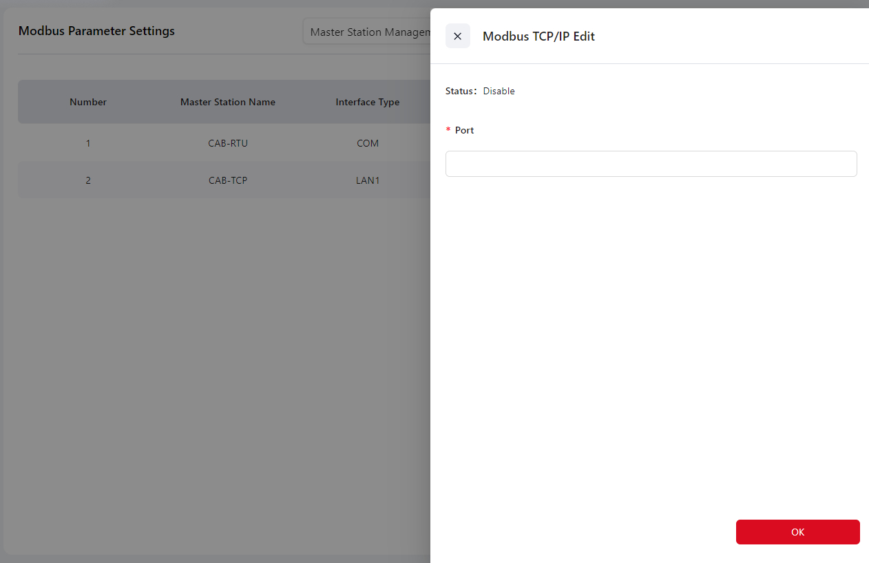
Operation steps:
- Click the Edit icon, then enter the port (range: 0–65535, default: 6502) in the Port field, and click Confirm.
- After configuration, power off the control cabinet, then restart and reconnect the robot to apply the settings.
- Once the connection with the master is established, write a program according to the Modbus Address Table (register addresses and function codes) to read the robot status or control robot I/O signals. You can also view the status in I/O Panel → Modbus.
Warning
Do not use common service ports such as 8080 or 80.
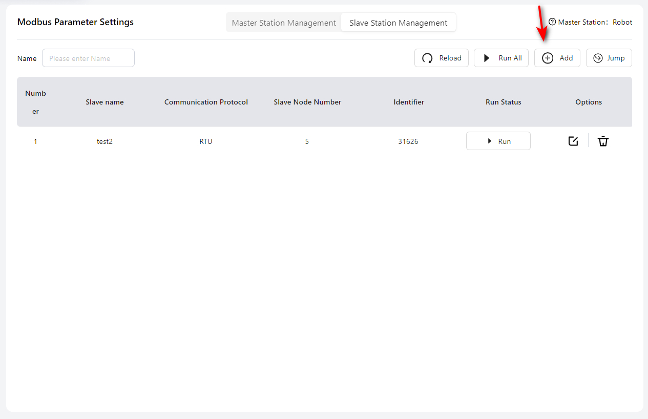
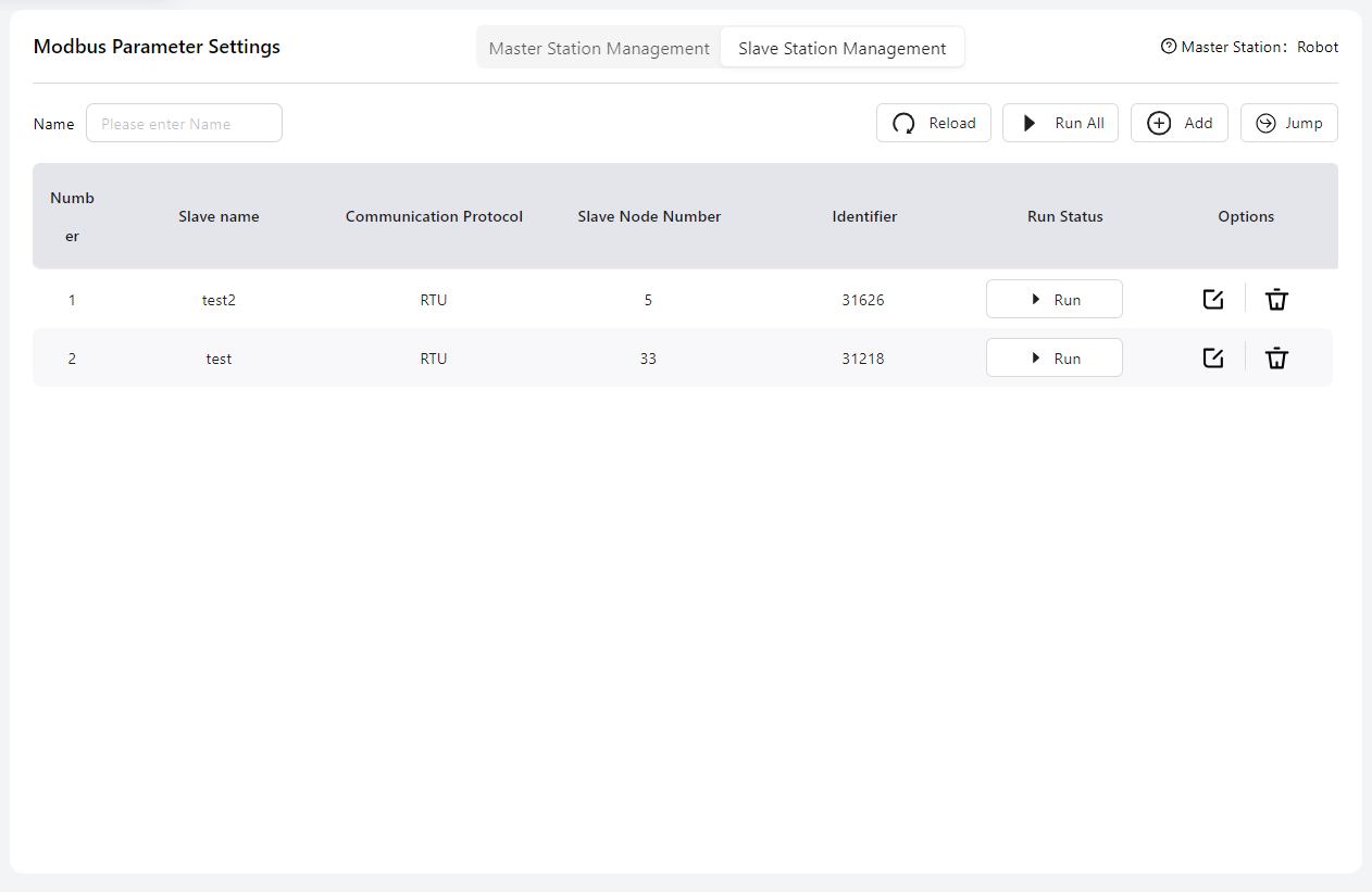
Slave Station Management
In this mode, Modbus acts as the slave, and the robot acts as the master.
Before configuration, connect the cables as follows:
- For Modbus TCP/IP, connect to the bottom Ethernet port of the standard control cabinet, or the LAN2 port of the MiniCab.
- For Modbus RTU, connect to the RS485 port on the front panel of the standard cabinet, or the PIN17 and PIN18 I/O ports on the front panel of the MiniCab.
For detailed interface locations and wiring instructions, please refer to the Hardware User Manual.
Warning
When configuring, make sure the robot is powered off.
Click Add to start configuration.
Modbus TCP/IP
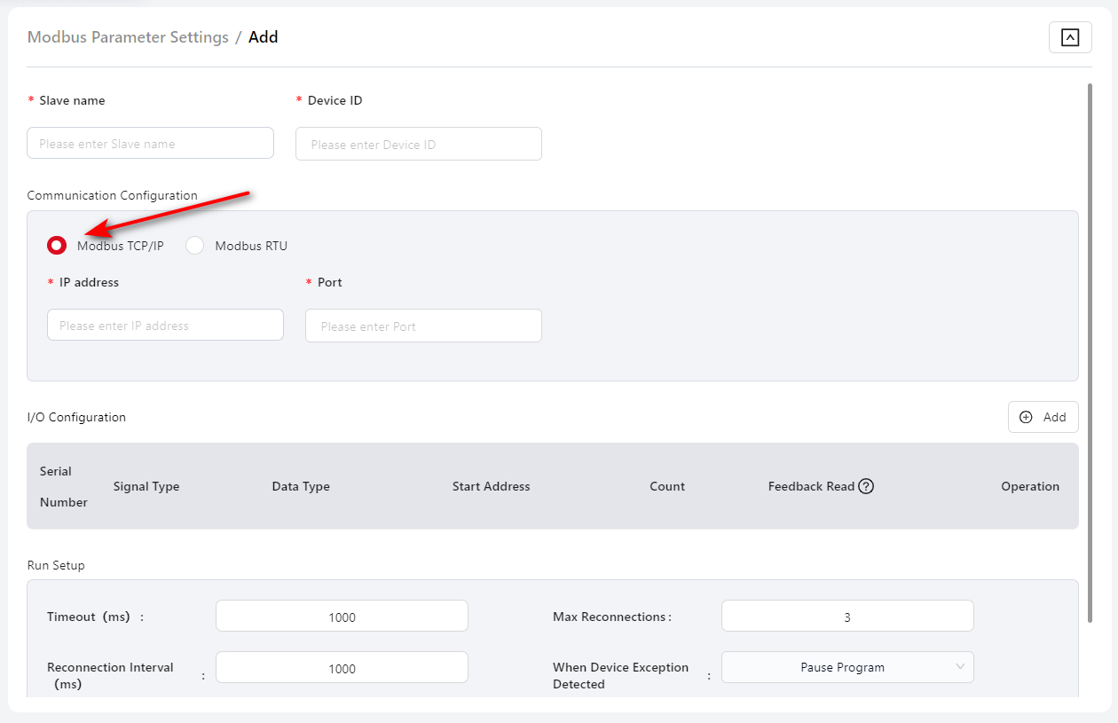
Slave Name: User-defined; must not duplicate the names of other modules.
Device ID: ID number of the slave device.
IP Address: IP address of the Modbus TCP/IP slave.
Port: Port number of the slave device.
I/O Configuration: Configure the register addresses and quantities for Modbus TCP/IP DI, DO, AI, and AO. Click Add to configure each DI, DO, AI, or AO individually.
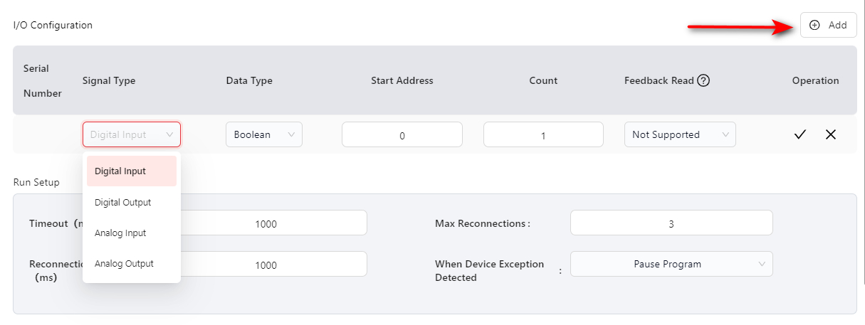
- Start Address: Less than 65536.
- Quantity: Supports up to 16 expansion I/O modules, 64 DIs, 64 DOs, 32 AIs, and 32 AOs.
- Readback read: Can be enabled or disabled; enabled by default.
Runtime Configuration:
- Timeout: Range 10–5000 ms, default 1000 ms.
- Reconnect Interval: When an error is first detected, reconnect immediately. Subsequent reconnections occur at the interval set here (range 1000–5000 ms, default 3000 ms).
- Max Reconnections: Range -1–99, default 3. -1: reconnect indefinitely. 0: do not reconnect.
- When device exception detected: Options — Pause Program (default) or Stop Program.
Modbus RTU
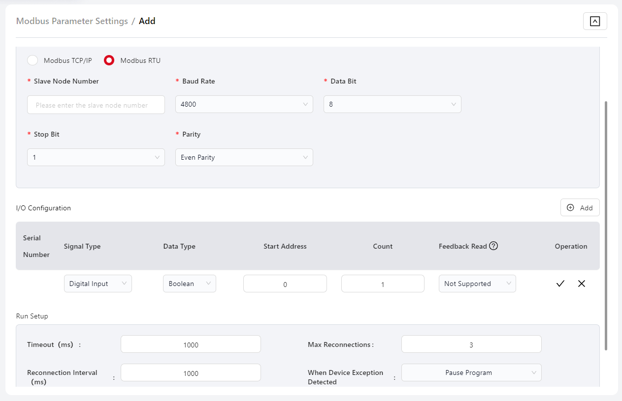
Slave Name: User-defined; must not duplicate the names of other modules.
Slave Node ID: Node number of the configured Modbus RTU slave.
Baud Rate: Select the baud rate of the Modbus RTU slave.
Data Bits: Select the data bit length.
Stop Bits: Select the stop bit length.
Parity: Select the parity mode.
I/O Configuration: Configure the register addresses and quantities for Modbus RTU DI, DO, AI, and AO. Click Add to configure each DI, DO, AI, or AO individually.
- Start Address: Less than 65536.
- Quantity: Supports up to 16 expansion I/O modules, 64 DIs, 64 DOs, 32 AIs, and 32 AOs.
- Readback read: Can be enabled or disabled; enabled by default.
Run Setup:
- Timeout: Range 10–5000 ms, default 1000 ms.
- Reconnect Interval: When an error is first detected, reconnect immediately. Subsequent reconnections occur at the interval set here (range 1000–5000 ms, default 3000 ms).
- Max Reconnections: Range -1–99, default 3. -1: reconnect indefinitely. 0: do not reconnect.
- When device error is detected: Options — Pause Program (default) or Stop Program.
After configuration, click Confirm. The configured Modbus list will be displayed on the main Modbus settings page:
Tips
If multiple Modbus RTU expansion modules are configured, their bus parameters (baud rate, stop bits, data bits, and parity) must be consistent.
About Identifier
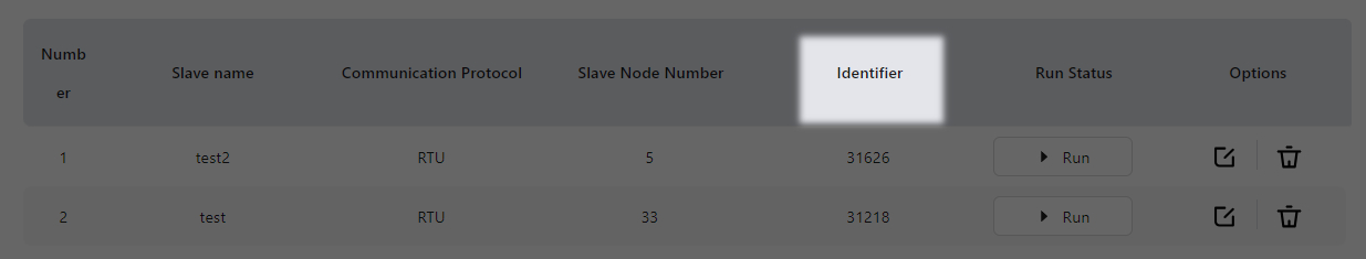
An Identifier is a unique ID automatically generated by the controller for each configured Modbus slave. It allows users to specify the Modbus slave in script programming by referencing this identifier.
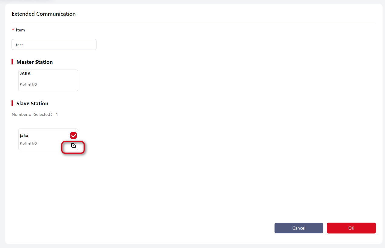
Extended Communication
JAKA robots support the PROFINET communication protocol and can act as a PROFINET master to connect with external devices.
After connecting the communication port on the side of the control cabinet, enter this page:
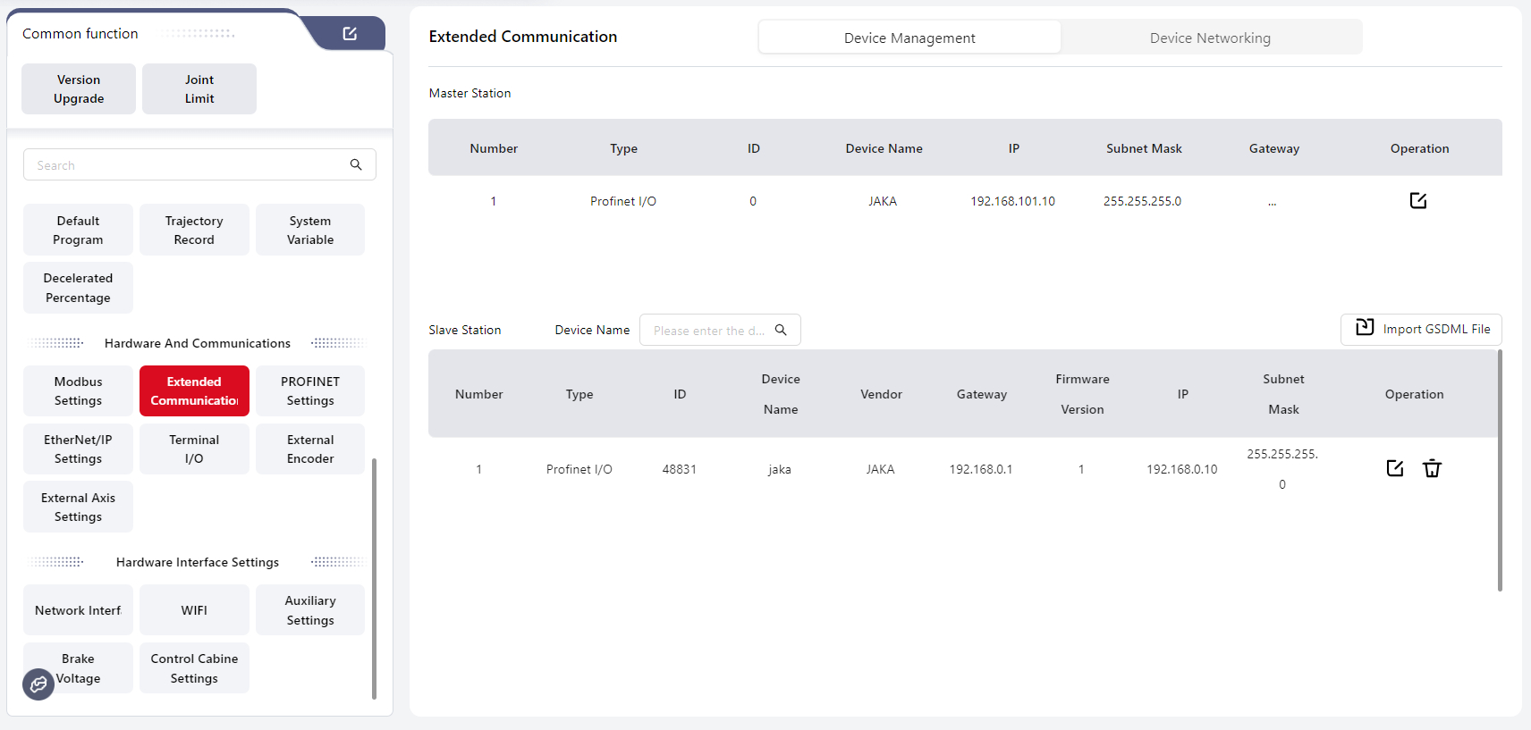
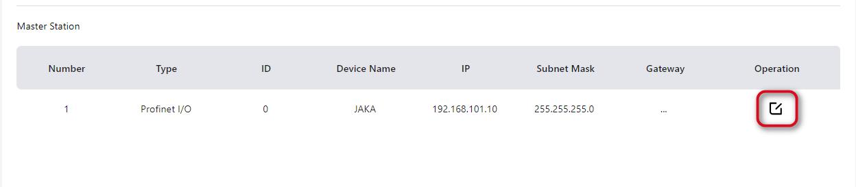
Device Management
Users can configure relevant information under the Master section:
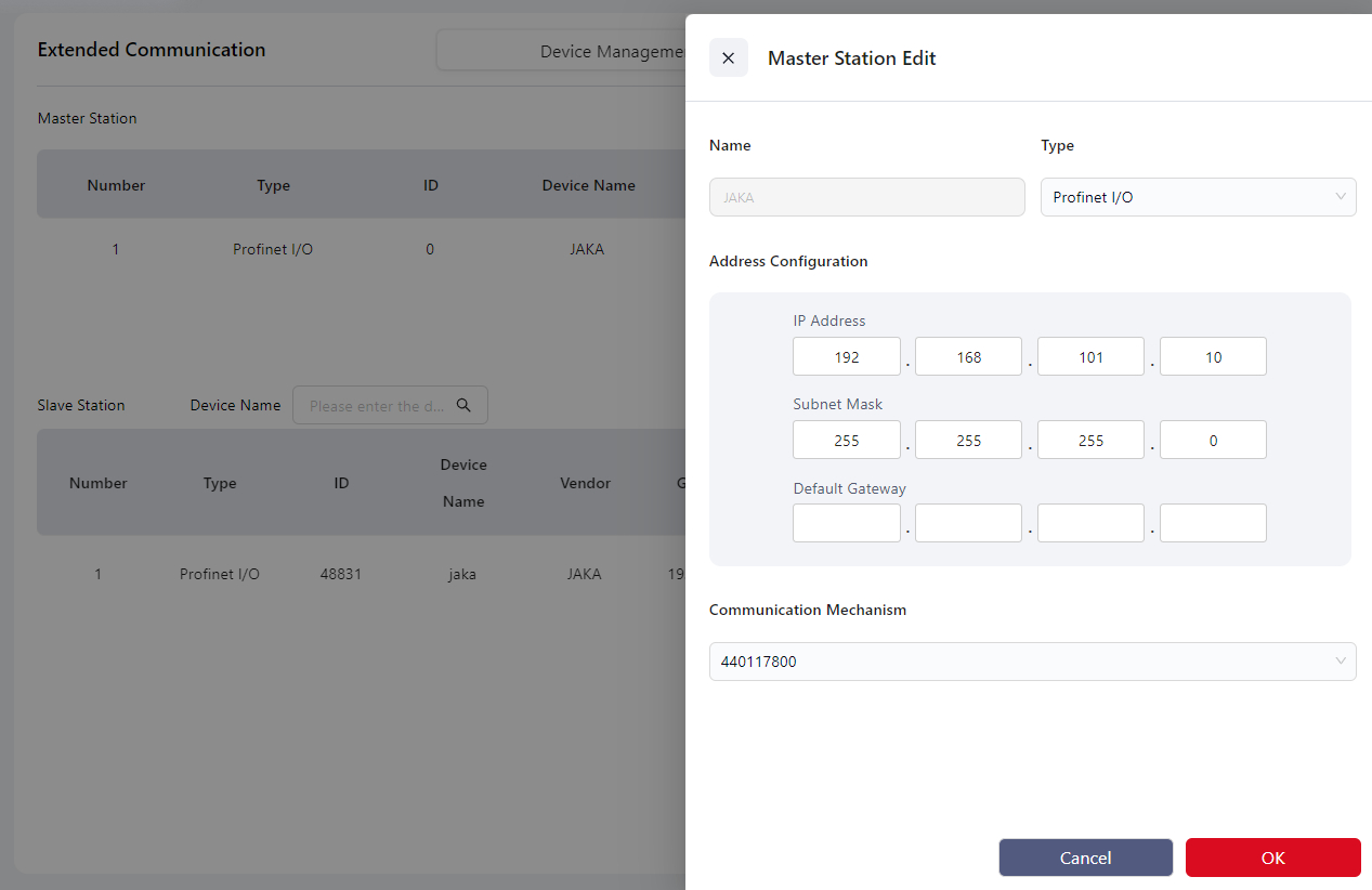
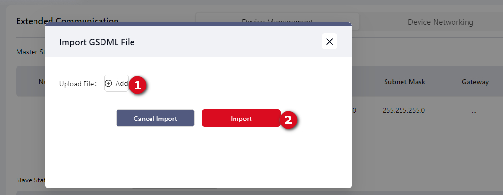
After configuration, continue by clicking Import GSDML File under the Slave section:
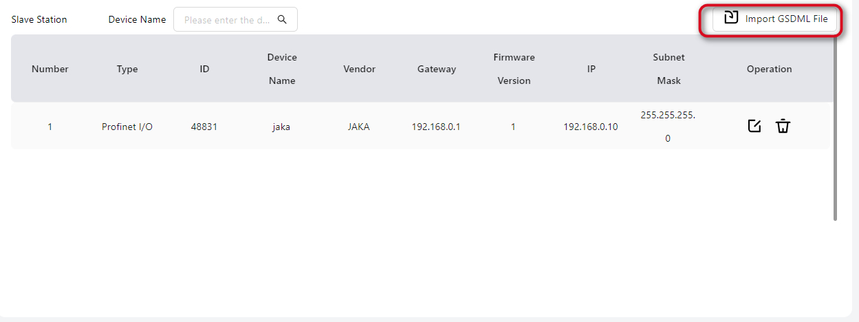
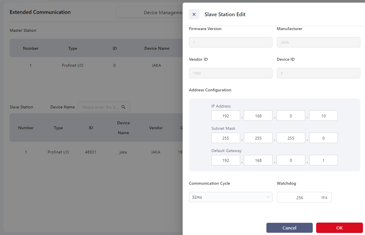
The imported slave device will appear in the list.
Click the Edit icon to modify related information:
After completing the above settings, proceed to the Device Networking page to configure the topology.
Device Networking

Click Add to enter the editing page.
Click the Edit icon again to enter the detailed configuration page:
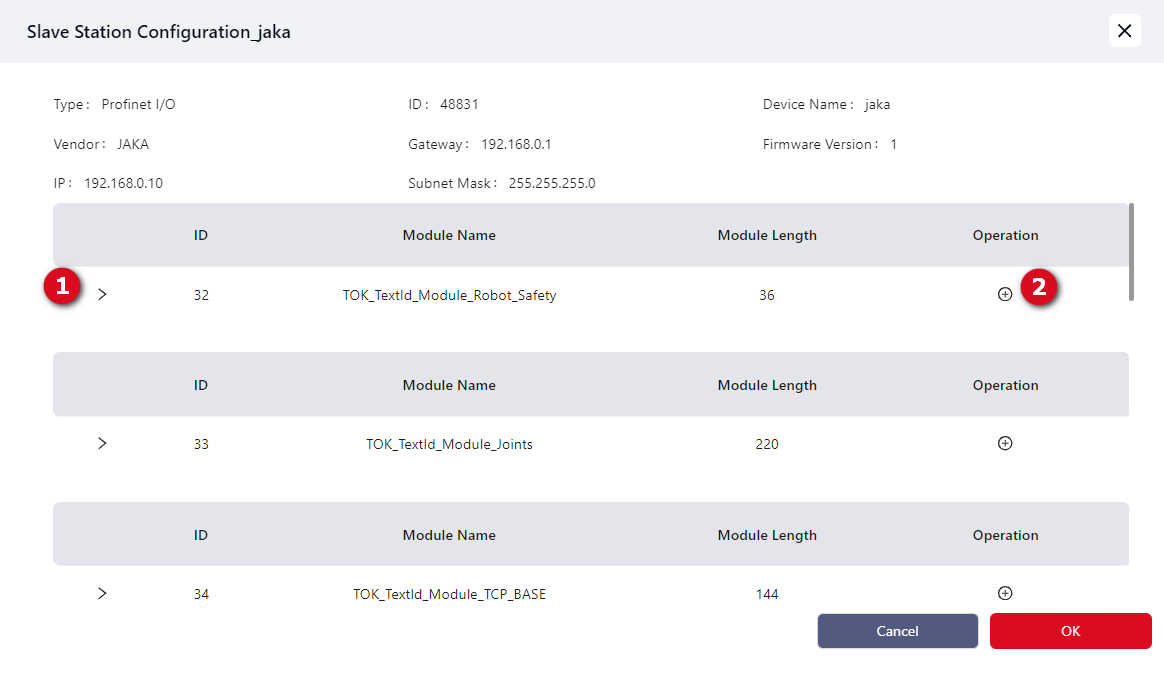
Click area 1 to open the dropdown list:
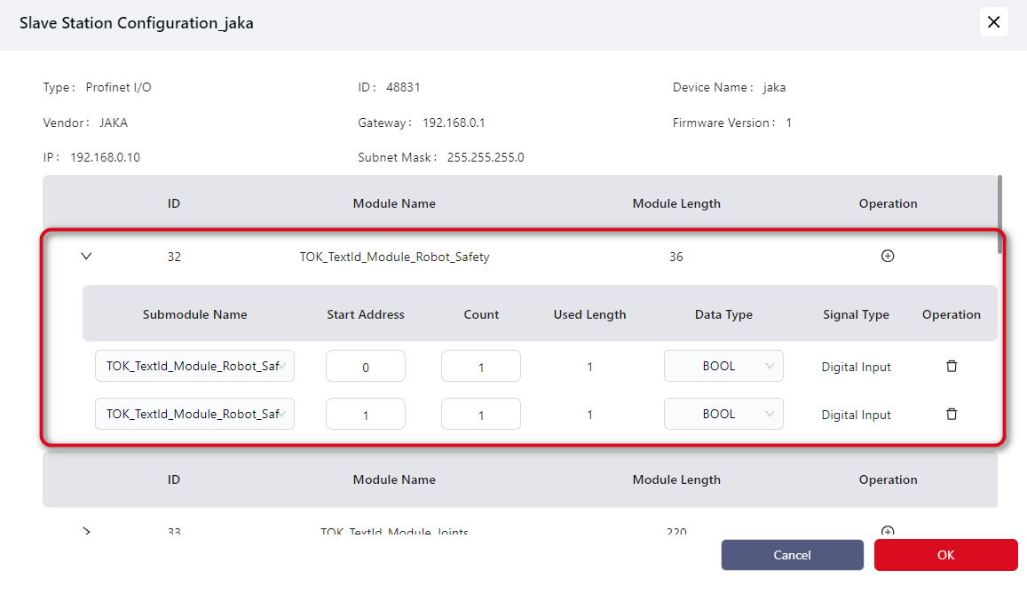
Click area 2 to add submodules:
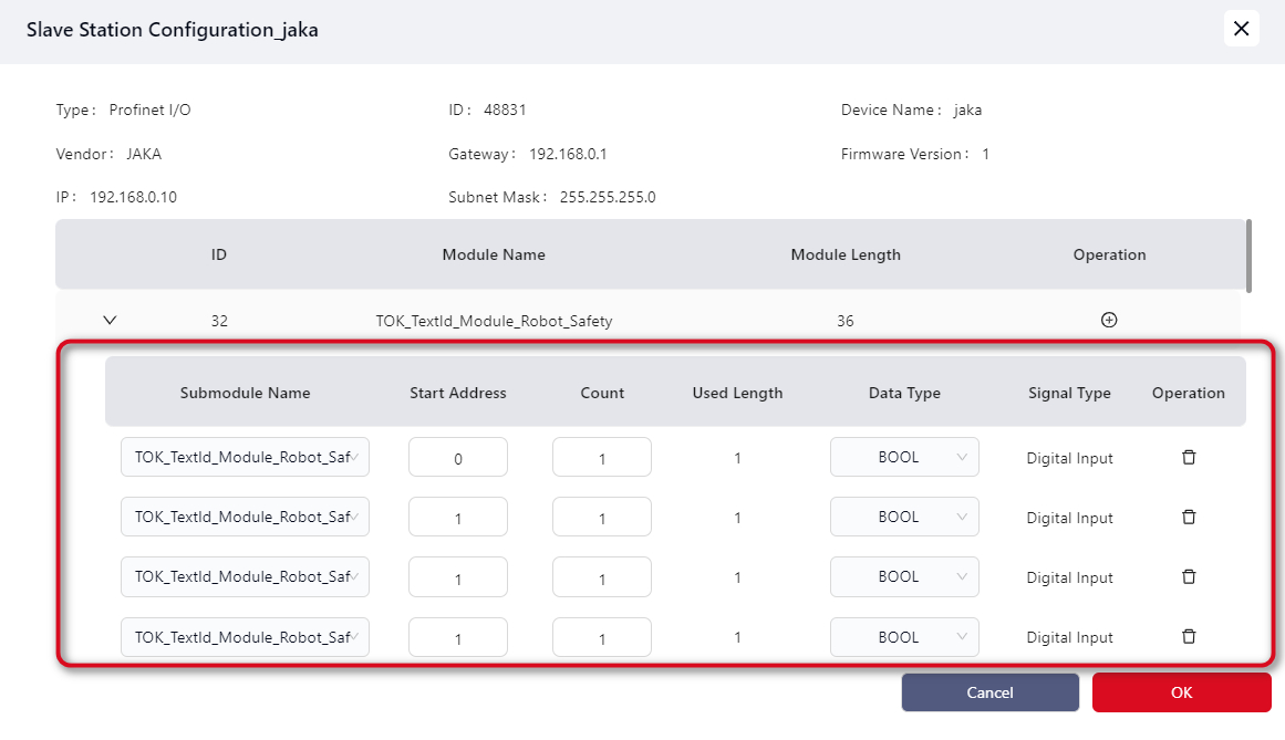
Tips
The total number of submodules cannot exceed a module length of 36. Refer to the table below for calculation details:
| Data Type | Type Length |
|---|---|
| BOOL | 1 |
| INT8 | 1 |
| UINT8 | 1 |
| INT16 | 2 |
| UINT16 | 2 |
| INT32 | 4 |
| UINT32 | 4 |
| INT64 | 8 |
| UINT64 | 8 |
| FLOAT | 4 |
| DOUBLE | 8 |
Example: A submodule of data type BOOL with a quantity of 4, plus four INT64 submodules with a total quantity of 32: 4 + 32 = 36, exactly reaching the module length limit.
If the total exceeds 36, the extra submodules will not take effect.
After editing, click Confirm to return to the page:
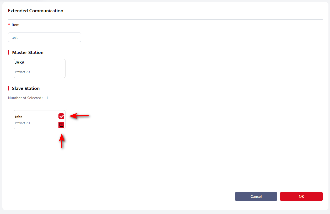
Tips
As shown above, edited cards are marked with a red edit icon.
Tick the checkbox and click Confirm again. Once configured successfully, you will return to the main page:
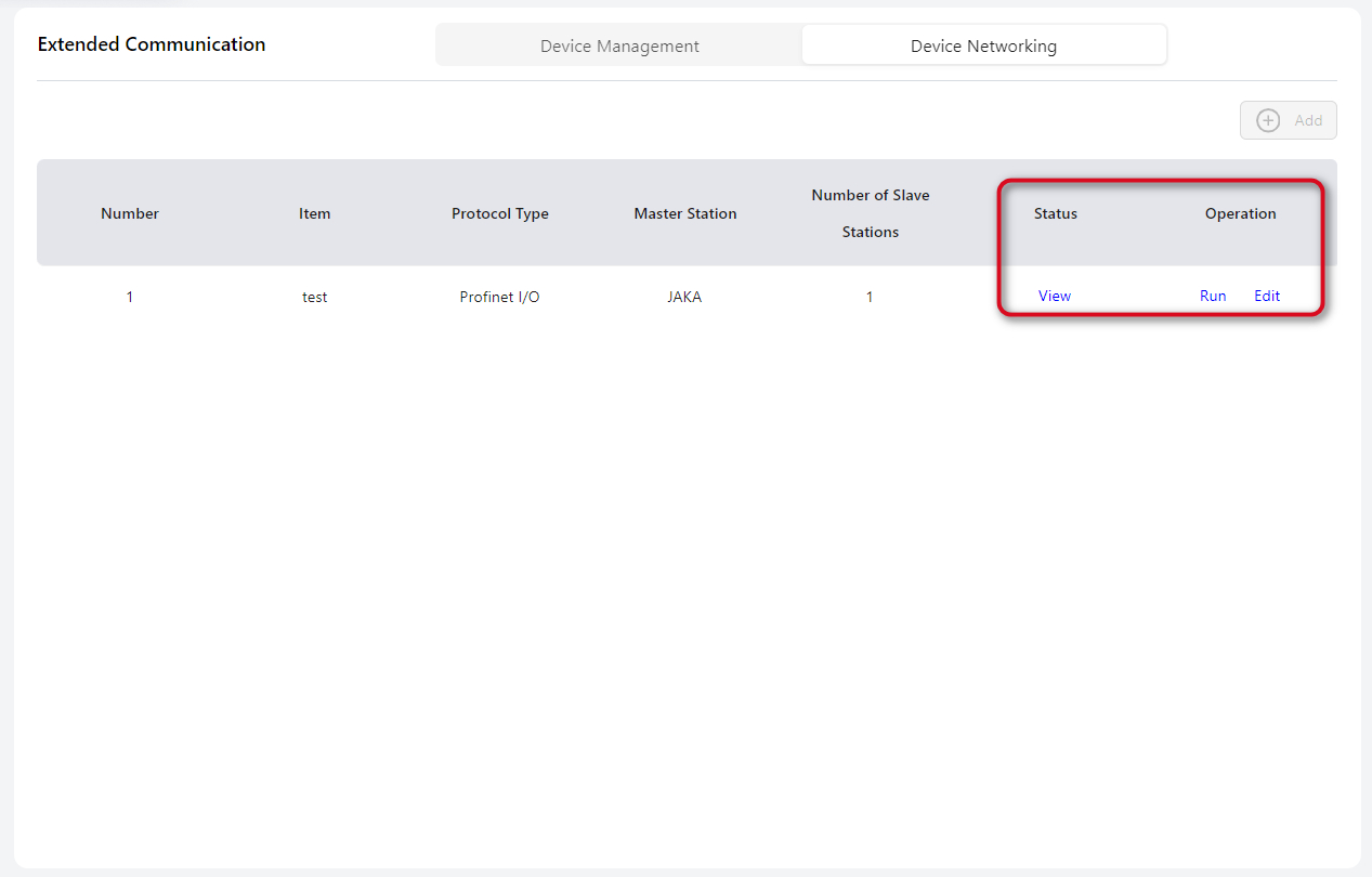
Further operations can be performed in the right-hand area.
The PROFINET master status can be viewed under I/O Panel → Extended I/O → PROFINET: PROFINET I/O.
PROFINET Settings
JAKA robots also support the PROFINET protocol in slave mode, enabling connection with external devices.
After connecting the communication port on the side of the control cabinet, enter this page and enable the PROFINET function. After enabling, restart the control cabinet to apply the changes.
Once activated, PROFINET can interact with external PLCs, and the I/O information will be displayed under I/O Panel → Fixed I/O.
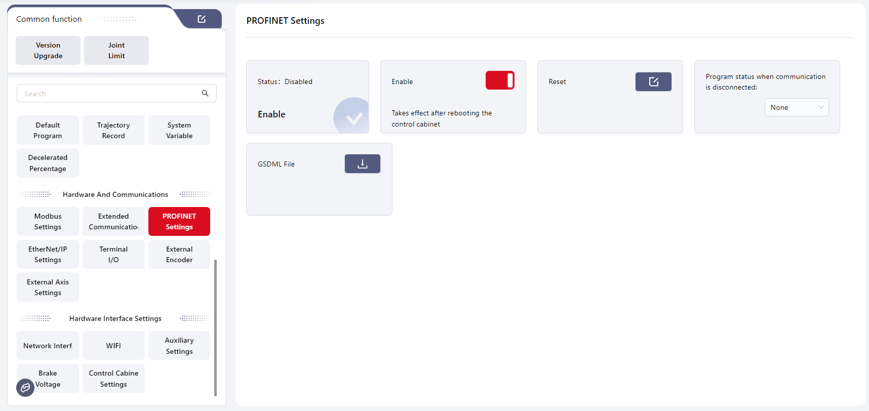
Click Reset to restore the PLC-side communication configuration of the PROFINET device, including its name, IP address, and enable status.
Tips
Default name: jaka Default IP address: 192.168.0.50
For details on using PROFINET I/O, see: PROFINET I/O
For the PROFINET address table, see: PROFINET I/O Address Table
Click the download icon next to GSDML File to export the file.
EtherNet/IP Settings
JAKA robots support the EtherNet/IP communication protocol and can act as an EtherNet/IP slave to connect with external devices.
After connecting the Ethernet port at the bottom of the control cabinet, enter this page and enable the EtherNet/IP function. After enabling, restart the control cabinet to apply the settings.
Once activated, EtherNet/IP can communicate with external PLCs. The I/O information will be displayed under I/O Panel → Fixed I/O.
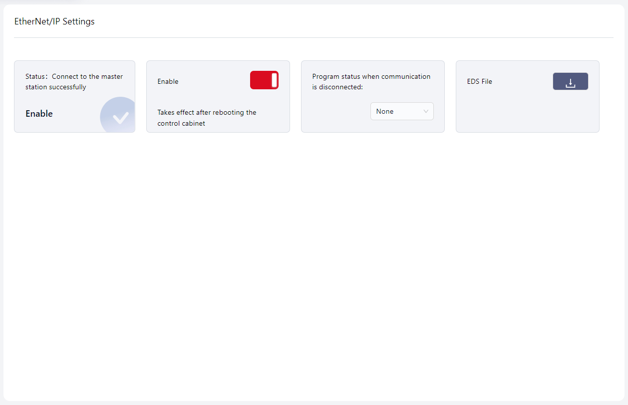
Users can set the robot’s program behavior when communication is lost in the area indicated by the arrow. The options include: None, Pause, and Stop.
- None: The program continues running without special response.
- Pause: The program pauses and resumes from the pause point once communication is restored.
- Stop: The program stops and restarts from the beginning when communication is restored.
Click the download icon next to EDS to export the file.
Tool I/O
Warning
This function is only applicable to TIO V3.
The robot’s end effector is equipped with a small I/O interface (TIO), which supports 2 digital inputs, 2 digital outputs, and 2 analog inputs. The 2 digital outputs can be multiplexed as a high-speed RS485 channel, and the 2 analog inputs can be multiplexed as a low-speed RS485 channel. It also supports configurable voltage outputs (12V / 24V / OFF) for powering external expansion devices.
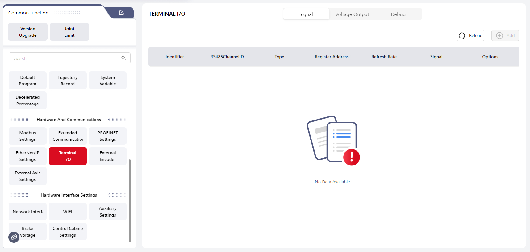
After connecting the end tool, go to I/O → Embedded I/O → Tool for configuration. The robot must be powered on but disabled.
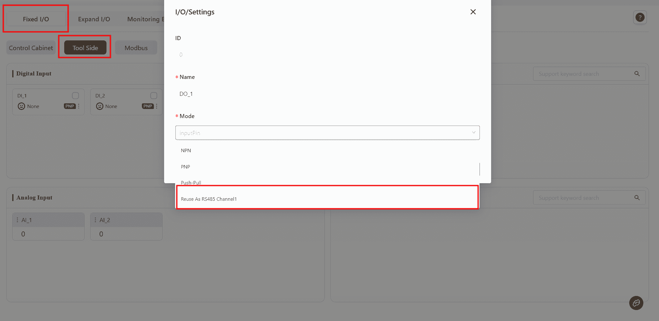
In the Digital Output section, select a DO channel and set its function to Multiplex as RS485 Channel 1, then click Confirm.
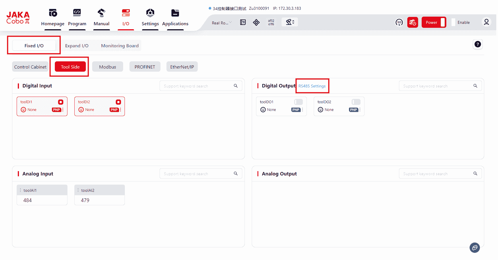
After configuration, an RS485 Configuration button will appear.
Click it to open the RS485 channel configuration interface.
Three modes are available for RS485 configuration:
- Modbus RTU
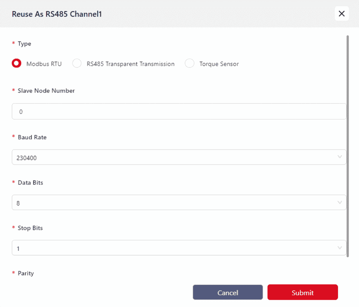
Mainly used for communication with external grippers or similar devices.
Currently, only Modbus RTU-compatible grippers are supported. Before connecting the gripper to the TIO terminal, verify the terminal connector definitions to ensure correct wiring.
For wiring instructions, refer to the corresponding model’s Hardware User Manual.
- RS485 Transparent Transmission
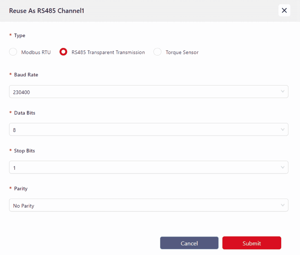
Currently, no devices are supported in this mode. It will be available in future software versions.
- Torque Sensor Mode
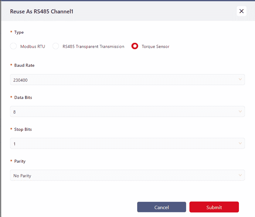
Mainly used for connecting VI-type torque sensors.
Warning
At present, the torque sensor only supports RS485 Channel 1.
Parameter Configuration
- Baud Rate: up to 230400
- Data Bits: 8 or 9
- Stop Bits: 1 or 2
- Parity: Odd, Even, or None
Incorrect parameter configuration may cause communication failure between the TIO and external devices.
External Encoder
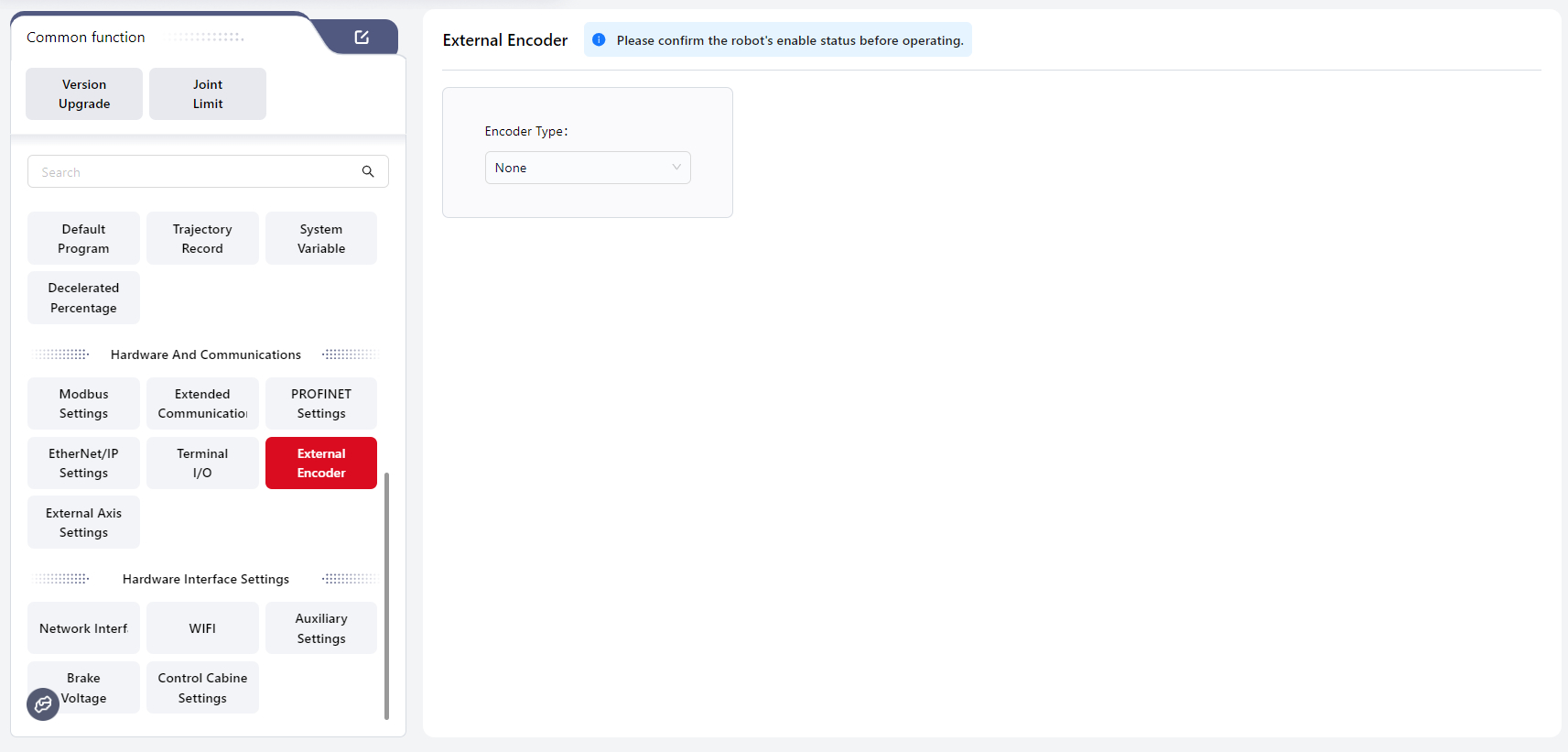
Users can configure an external encoder on this page. Three options are available: None, Incremental, and Absolute.
The default setting is None, in which case no encoder configuration parameters are displayed.
An incremental encoder is connected through the HSI interface, while an absolute encoder is mapped through a Modbus slave. Their configuration options differ and are dynamically displayed based on the selected encoder type.
Details are as follows:
Incremental
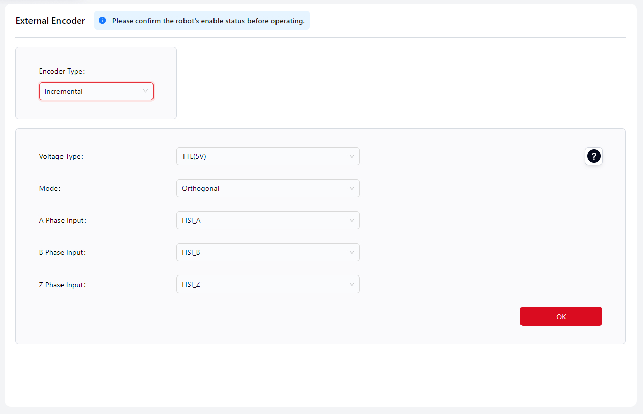
This section allows configuration of an external incremental encoder connected via the HSI interface on the control cabinet. Currently, the HSI interface supports connection of one encoder at most.
Signal Level Type: TTL, HTL
- TTL corresponds to 5V level.
- HTL corresponds to 24V level.
Mode: Quadrature
- Only quadrature mode input is supported.
A-phase Input: HSI_A
B-phase Input: HSI_B
Z-phase Input: HSI_Z
Tips
Each HSI port includes both P and N pins:
- For a three-wire encoder, connect phases A, B, and Z to HSI_A_P, HSI_B_P, and HSI_Z_P, respectively.
- For a six-wire encoder, connect A phase to HSI_A_P and HSI_A_N, B phase to HSI_B_P and HSI_B_N, and Z phase to HSI_Z_P and HSI_Z_N.
Absolute
This section allows configuration of an external absolute encoder mapped through a Modbus slave. Currently, only one encoder can be added. Click Add to manually create a configuration:
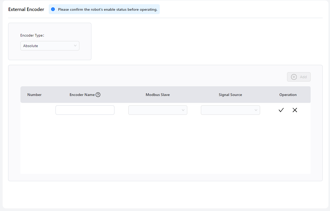
- Encoder Name
- Modbus Slave: Select a previously configured Modbus slave.
- Signal Source: Select the analog input signal from the Modbus slave.
- Click √ to complete the configuration.
External Axis Settings
An external axis is used to extend the robot’s degrees of freedom or to transform the position and orientation of a workpiece. It can be controlled independently or in synchronization with the robot, enabling more efficient and flexible robotic applications.
External Axis Management
After connecting the external axis, open the current interface to perform the configuration. Before configuration, ensure that the robot is in the power-off and disabled state.
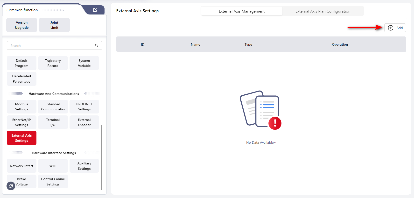
Click Add, then configure the following parameters in the pop-up window:
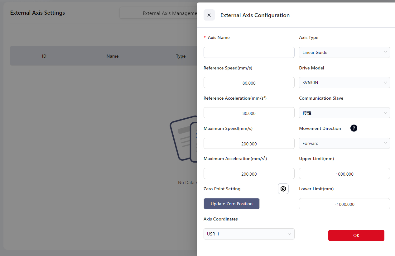
Axis Name, Axis Type, Reference Speed, Drive Model, Reference Acceleration, Communication Slave, Maximum Speed, Motion Direction, Maximum Acceleration, Upper Limit, Zero Point Setting, Lower Limit, and Axis Coordinates.
`Axis Coordinates`: Coordinate system for storing the external axis Cartesian position output values.
After completing the configuration, click Confirm.
Click Enable, the set external axis can put into use.
Currently only 1 external axises can be set.
Tip:
When delete an axis or add a new axis, the system needs to be rebooted once to activate the axis settings.
After rebooting, please power on and enable the robot, then enable the axis to use.
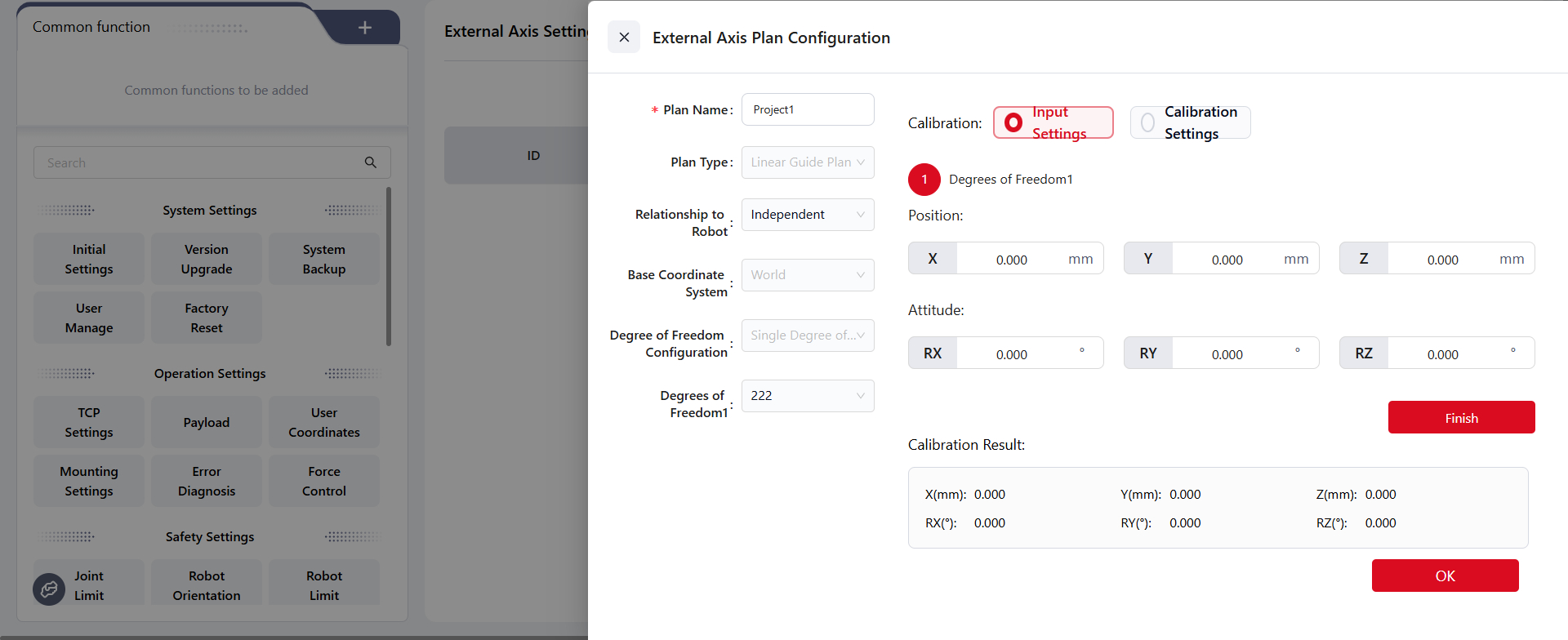
External Axis Plan Configuration
After configuring the external axis, users can proceed with the external axis plan configuration.
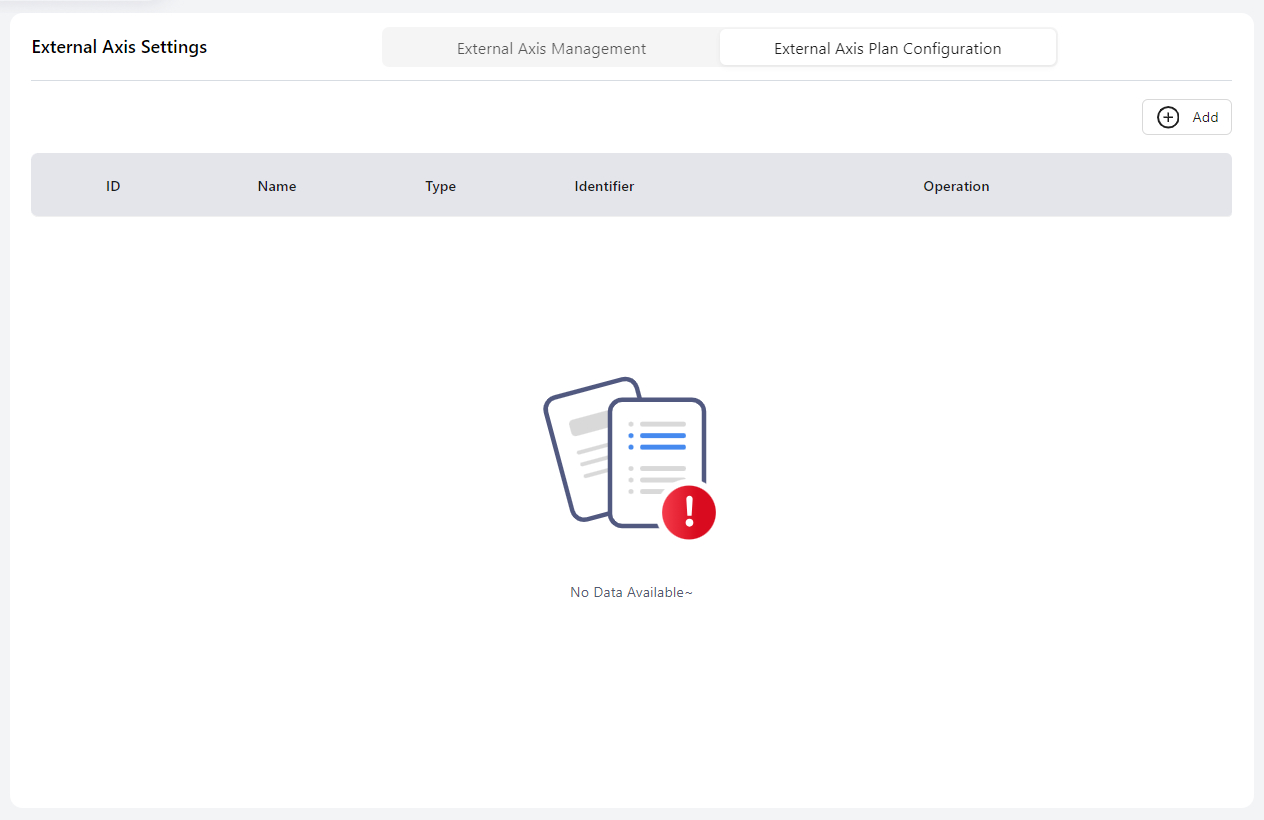
Click Add, and in the pop-up window, configure parameters such as Plan Name, Plan Type, Relationship to Robot, Plan Base Coordinate System, Degree of Freedom Configuration, DOF 1, etc.
Relationship to Robot:
- Independent: The robot base is not connected to the external axis. Movement of the external axis does not affect the robot’s pose in the world coordinate system.
- Combined: The robot base is connected to the external axis. Movement of the external axis will directly change the pose of the robot base in the world coordinate system.
::: Warning When finished the settings above, click Confirm first before proceed to the Calibration part. :::
About Calibration:
The purpose of calibration is to determine the coordinate system description of the external axis origin output in the world coordinate system.
If the external axis and the robot are in a combined configuration, the external axis must be calibrated before the user coordinate system can be used.
For motion systems that include external axes, it is important to properly define the world coordinate system. Currently, the Z-axis of the world coordinate system must be set opposite to the direction of gravity, while the XY directions can be freely defined by the user.
Before performing external axis calibration, the user must confirm the world coordinate system in Settings → Installation Settings.
This configuration defines the relationship between the robot base coordinate system and the world coordinate system.
When entering the calibration interface, the world coordinate system is determined by the installation orientation.
The coordinate system obtained from external axis calibration (the output-end coordinate system) is also defined relative to the world coordinate system.
If the system is in a combined configuration, the installation orientation will be updated after calibration to describe the relationship between the robot base and the external axis output-end coordinate system.
Warning
Throughout the entire process, the world coordinate system is uniquely defined in physical space and does not move. Whenever recalibration is required, it is recommended that the user reconfigure the robot’s mounting orientation and reference coordinate system before performing the new calibration.
In the Calibration section, two configuration methods are available:
Input Settings– Directly enter the position and orientation values, then clickFinish. Verify the calibration result in the field below, and click Confirm to complete the configuration.
Calibration Settings– As shown in the reference diagram, switch to the manual interface and move the robot and external axis to the appropriate positions.
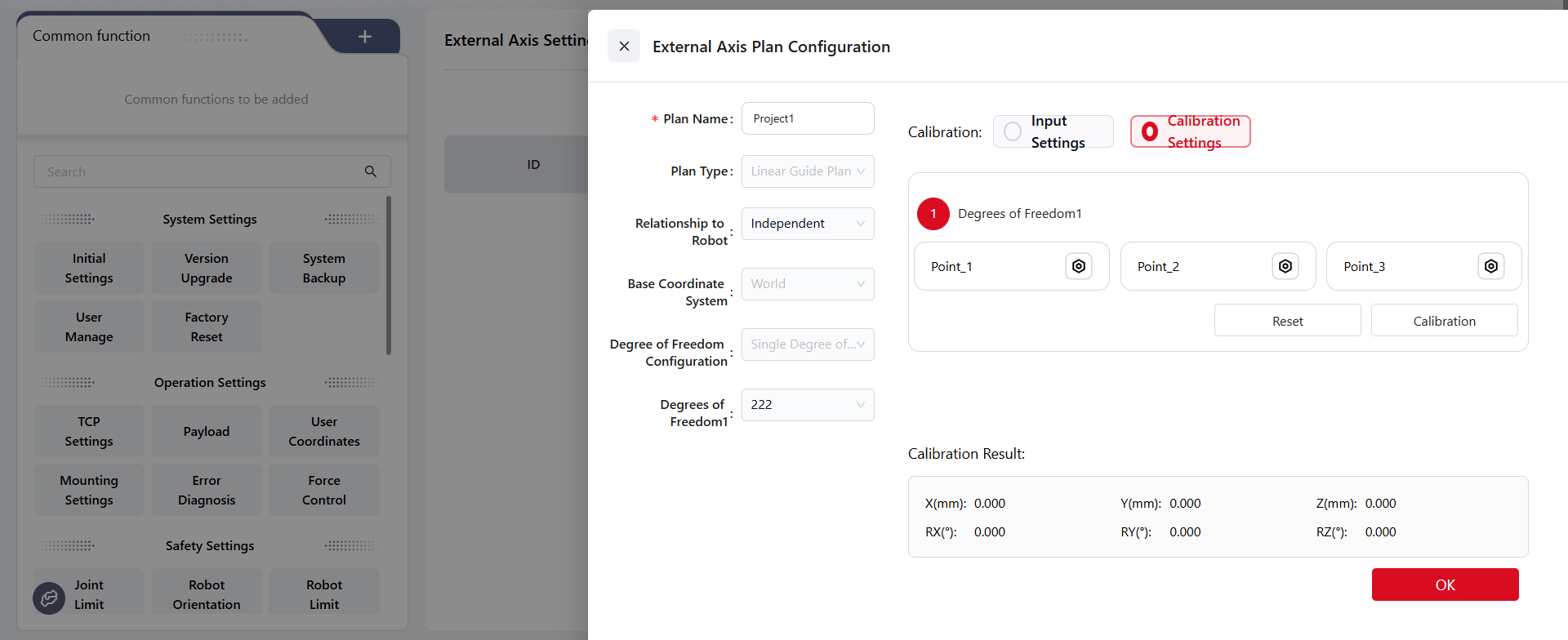
Verify the calibration result in the field below, then click Confirm to complete the configuration.
Hardware Interface Settings
Network Interface
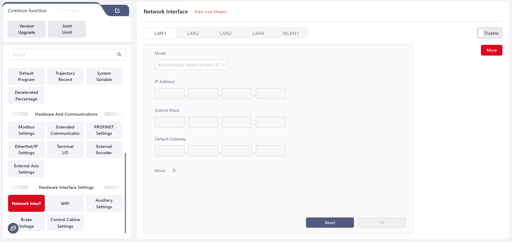
Users can configure the robot’s network interfaces on this page, enabling communication with external devices, control systems, other robots, or host computers.
Configuration options for each network port are as follows:
- LAN1: Supports both dynamic and static IP. Default: static IP (10.5.5.100/24) with DHCP service enabled.
- LAN2: Supports both dynamic and static IP. Default: static IP (192.168.100.100).
- LAN3: Fixed static IP, not user-configurable.
- LAN4: EtherCAT interface, not user-configurable.
- WLAN1: Supports both dynamic and static IP and provides DHCP service.
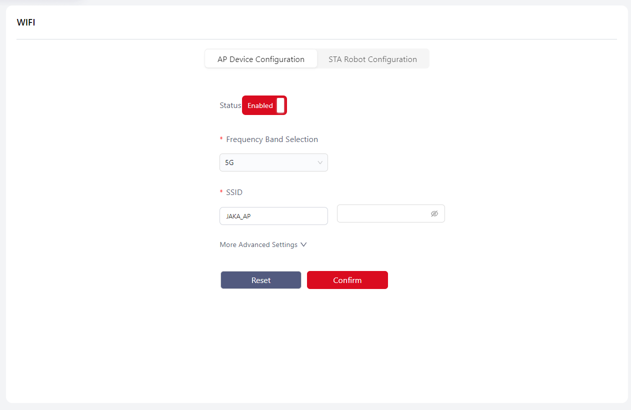
Wi-Fi
Users can configure the robot’s Wi-Fi connection on this page to enable communication with external terminals or devices within a local network.
AP Mode Configuration
Warning
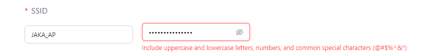
Note: When opening this page for the first time, users will be prompted to change the SSID password:
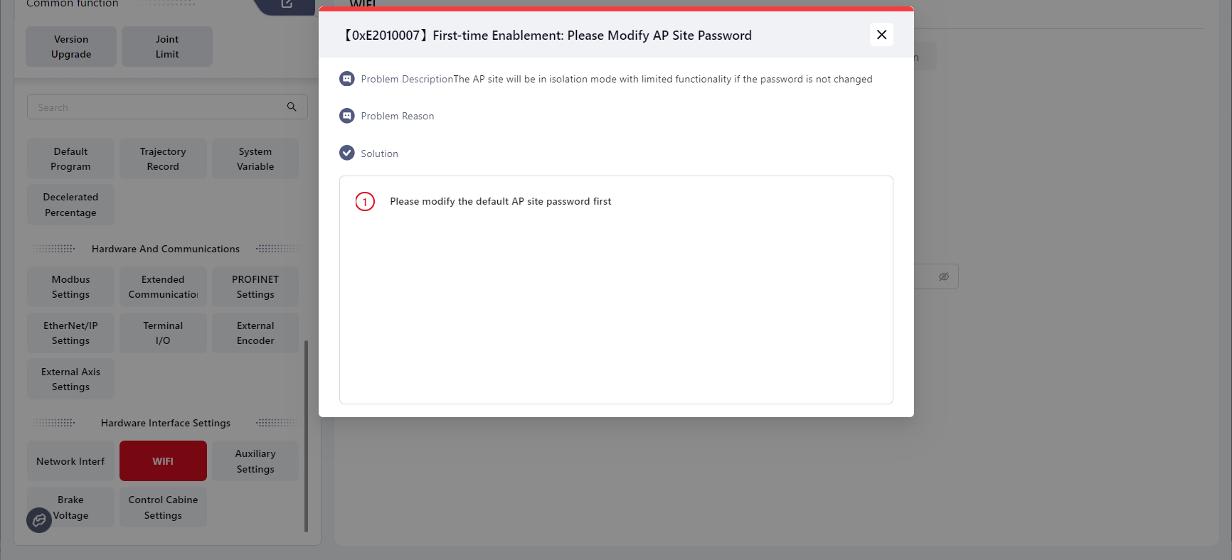
The new password must meet the following rules:
If the password is not changed, the AP will remain in ap_isolate mode, meaning that devices connected to the AP cannot communicate with each other.
Frequency Band: 2.4 GHz or 5 GHz (default: 2.4 GHz).
SSID: Default is the control cabinet ID. Users can modify it (maximum 128 bytes, cannot be 0 bytes). Password protection is optional.
Advanced Settings:
- Channel selection: ACS (Automatic Channel Scan) or Manual (default: ACS).
STA Mode Configuration
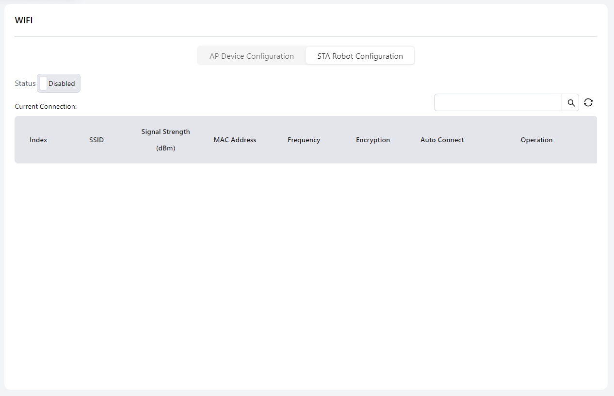
- Supports Wi-Fi hotspot scanning, displaying up to 15 networks. The current and last connected networks are shown at the top of the list.
- Supports Auto Connect on/off setting.
Auxiliary Hardware Settings
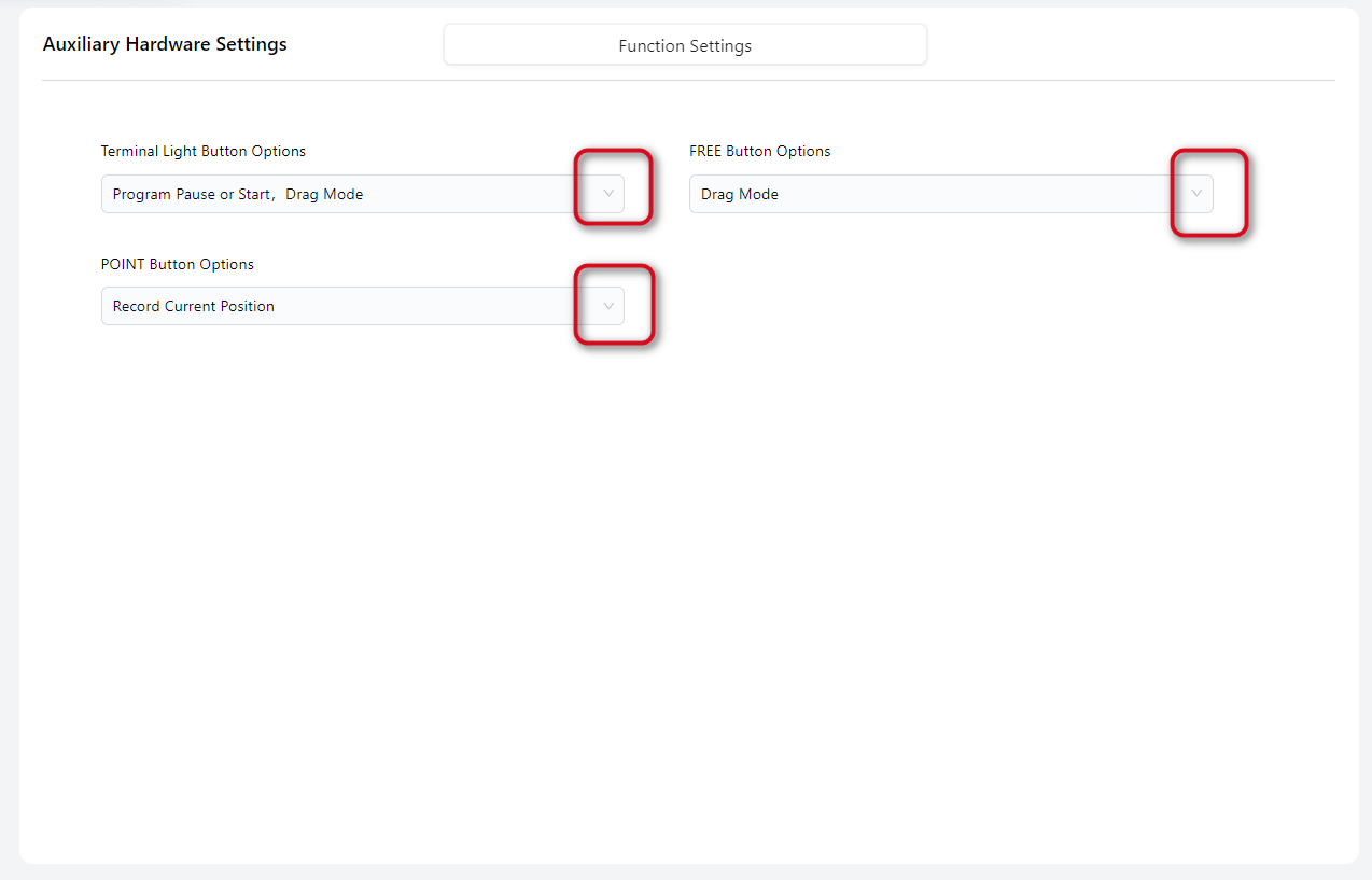
JAKA robots have three buttons on the robot arm: Terminal Light Button, FREE Button, and POINT Button. Users can configure their functions and the control cabinet power supply voltage through the dropdown menus on this page.
Tips
- Disable Function means to turn off the selected function. By default, all functions are enabled.
- Press and hold the FREE button to enter drag mode. Press and release the FREE button to pause or resume the program and record the current point.
- When the program is paused or running, the robot cannot enter drag mode.
- The Terminal Light Button, if not disabled, can be used to clear collision alarms after a collision occurs.
Brake Voltage
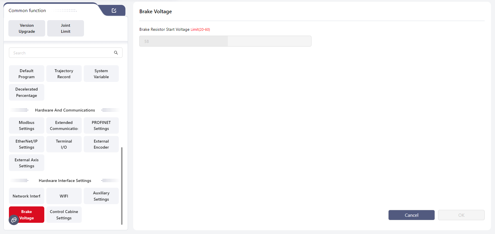
Warning
Note: This feature applies to CAB LiteDC only.
CAB LiteDC integrates a brake voltage circuit to dissipate back electromotive force (EMF) generated during robot deceleration and braking. When an external power supply is used, the brake voltage must be configured to prevent overvoltage shutdown or controller damage.
The robot must be powered off before setting the brake voltage.
The brake voltage V-Brake and input voltage V-IN must satisfy the condition: V-Brake ≥ (V-IN + 3) V.
Recommended settings for typical power supply types are shown below:
| Power Supply Type | Input Voltage V-IN[1] | Brake Resistor Start Voltage V-Brake[2] |
|---|---|---|
| 48 V Power Module | 48 V | 51 V |
| 48 V Lithium Battery | 54.6 V | 58 V |
| 24 V Power Module [3] | 24 V | 27 V |
Control Cabinet I/O Settings
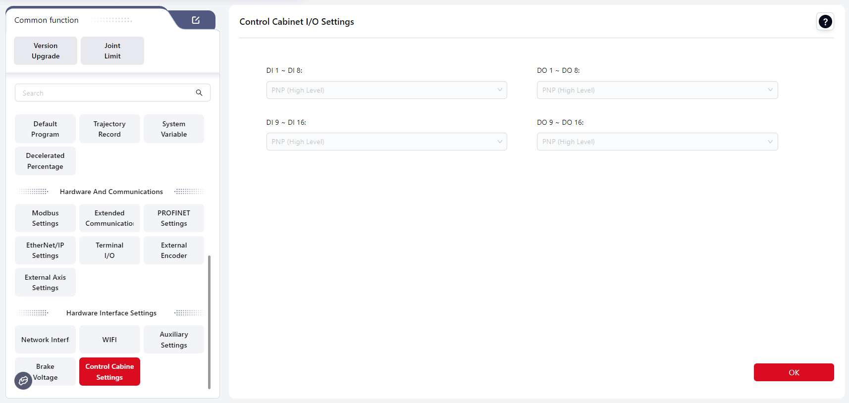
Users can configure the trigger type (PNP/NPN) for each DI and DO group on the control cabinet.
The default setting is PNP. Click the dropdown menu to change the setting, then click OK to apply.
Warning
Note:
When configuring I/O options, an I/O check will be performed:
- If the selected I/O group is already occupied by another function, a popup will display: “Detected I/O conflict. Configuration failed. Please check whether the I/O is used by another module.” The dropdown will revert to its original value.
- If the selected I/O group is available, a popup will display: “Configuration successful.”
The input voltage is a typical value and must not exceed 60 V. If V-IN > 56 V, the robot overvoltage threshold must be adjusted. ↩︎
If V-Brake < (V-IN + 1) V, the system will enter power-on protection and display “Body voltage or configuration error.” ↩︎
The 24 V power module is used for MiniCobo 1 only and cannot be used for Zu, C, or Pro series robots. ↩︎