I/O
I/O Panel
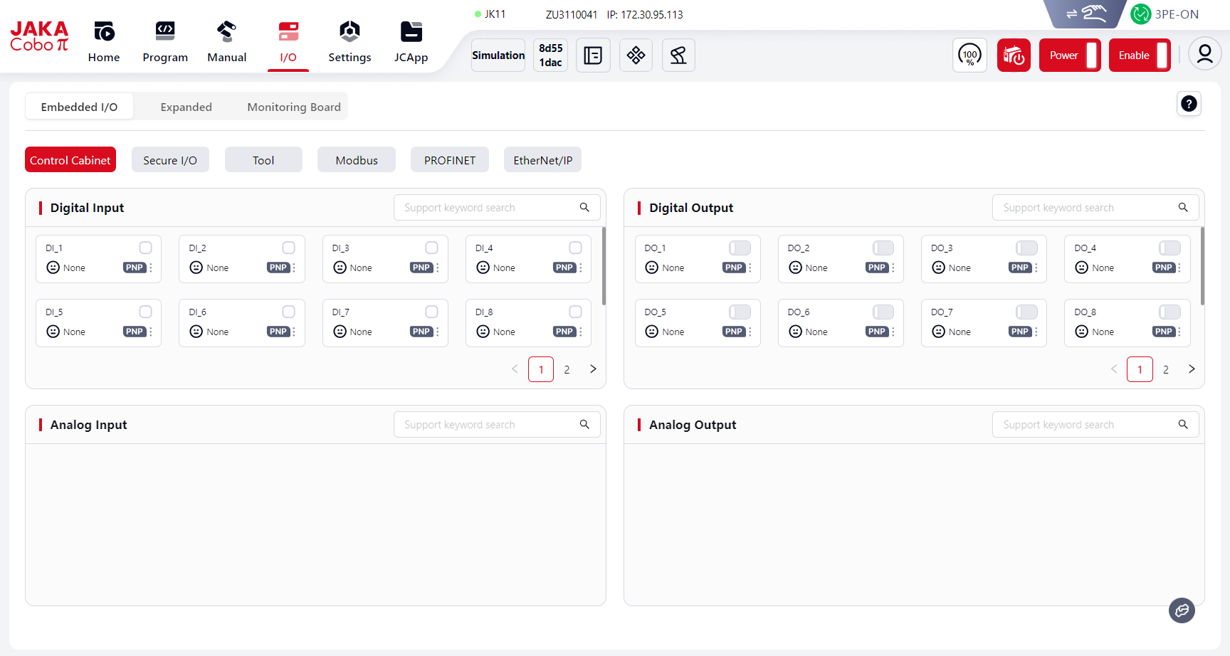
Users can view and configure the electrical I/O of the robot control cabinet in the I/O panel.
Attention:
When setting I/O, the robot must be disabled first.
Fixed I/O
There are six types of fixed I/O. Among them, Control Cabinet I/O, Safety I/O, Tool I/O, and Modbus I/O are enabled by default.
PROFINET I/O and EtherNet I/O must be enabled in Settings before they appear here.
DI/DO Card Description:
In the I/O panel, DI/DO cards for Fixed I/O, Extended I/O, and Monitoring Board share the same format.
The explanation is given below:
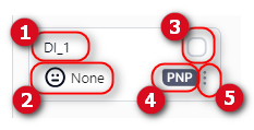
1 DI/DO name, user-editable.
2 DI/DO function, user-selectable.
3 DI/DO status.
4 Control cabinet DI/DO type (PNP or NPN).
5 Click this icon or any blank area of the card to open the Settings page for configuring the DI/DO name and function.
Control Cabinet
The standard control cabinet is CAB 3.0, with the following specifications:
- 16 DI (configurable as NPN/PNP)
- 16 DO (configurable as NPN/PNP)
When using Coboπ connected to CAB 3.0, the I/O panel displays the cabinet’s physical signals. Full I/O can be viewed by scrolling.
Digital Input (DI)
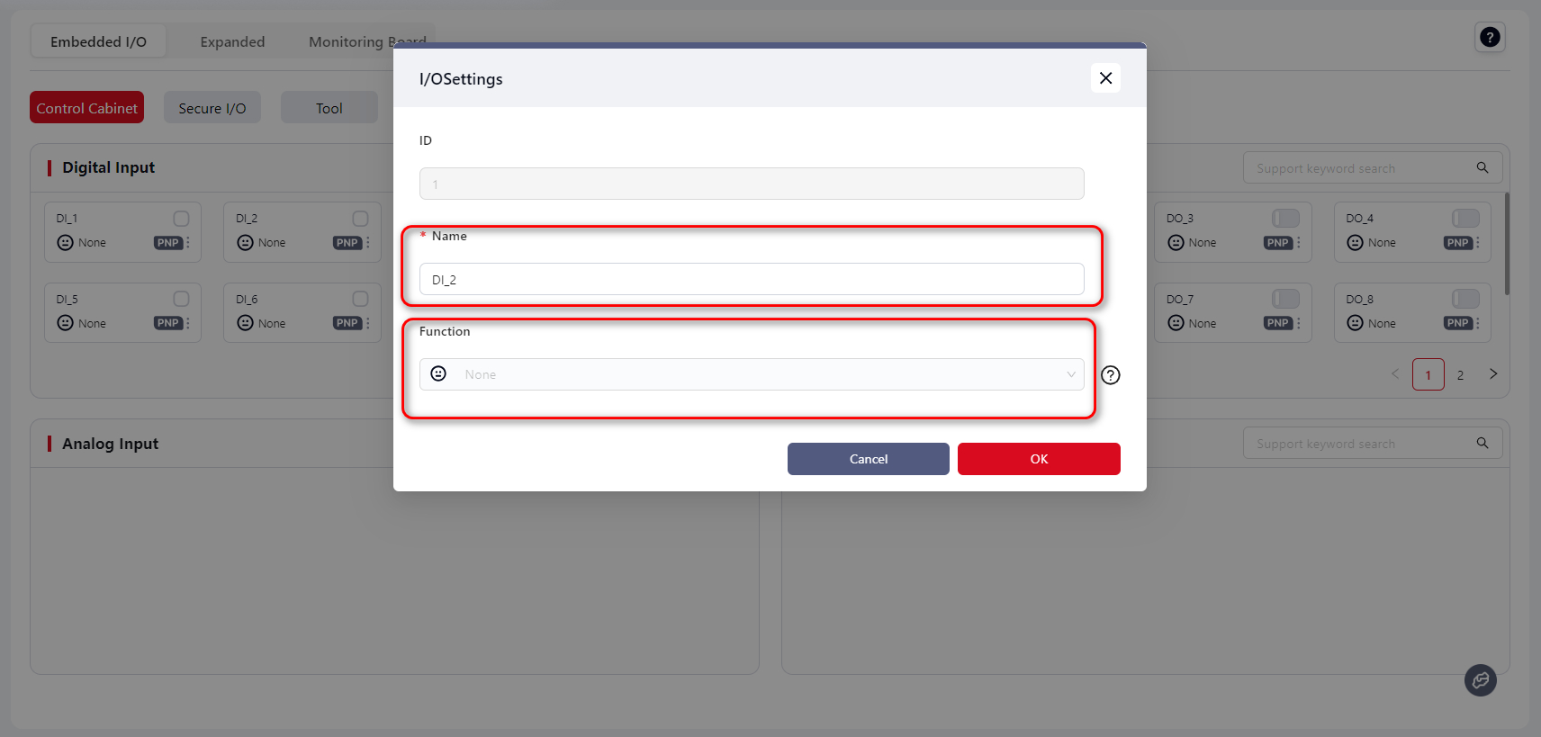
Edit the DI name under Name, and select its function from the drop-down list under Function.
When the DI signal is triggered, the selected function is activated.
Currently supported DI functions are listed below:
| Icon | Function | Description | Trigger |
|---|---|---|---|
 | None | No function | None |
 | Start Program | Runs the currently open program in Programming Control when triggered. Typically used to resume a stopped program. Note: Save the program before triggering this DI. If unsaved, Coboπ runs the last saved program. | Rising edge |
 | Pause Program | Pauses the currently open program. Resume with the Continue Program DI. | Rising edge |
 | Continue Program | Resumes the paused program. | Rising edge |
 | Stop Program | Stops the currently open program. Restart with Start Program DI. | Rising edge |
 | Power On Robot | Powers on the robot. | Rising edge |
 | Power Off Robot | Powers off the robot. | Rising edge |
 | Enable Robot | Enables the robot. | Rising edge |
 | Disable Robot | Disables the robot. | Rising edge |
 | Speed Level 1 | Robot slows down and enters speed level 1 mode. | Low level |
 | Protective Stop | Robot motion stops. This can only be triggered when the robot is controlled by the teaching pendant or external control source. | Low level |
 | Move to Safe Pose | Robot moves to the safe pose defined in Settings – Safety Settings – Robot Pose. | High level |
 | Speed Level 2 | Robot slows down and enters speed level 2 mode. | Low level |
 | Clear Collision | Clears collision alarms. | Rising edge |
 | Enter Drag Mode | Robot enters drag mode. | Rising edge |
 | Exit Drag Mode | Robot exits drag mode. | Rising edge |
Note:
- Speed Level 2 must be lower than Speed Level 1.
- Functional I/O detects edge signals (rising/falling). To avoid communication delay, keep the signal level stable for at least 500 ms before and after the edge.
Digital Output (DO)
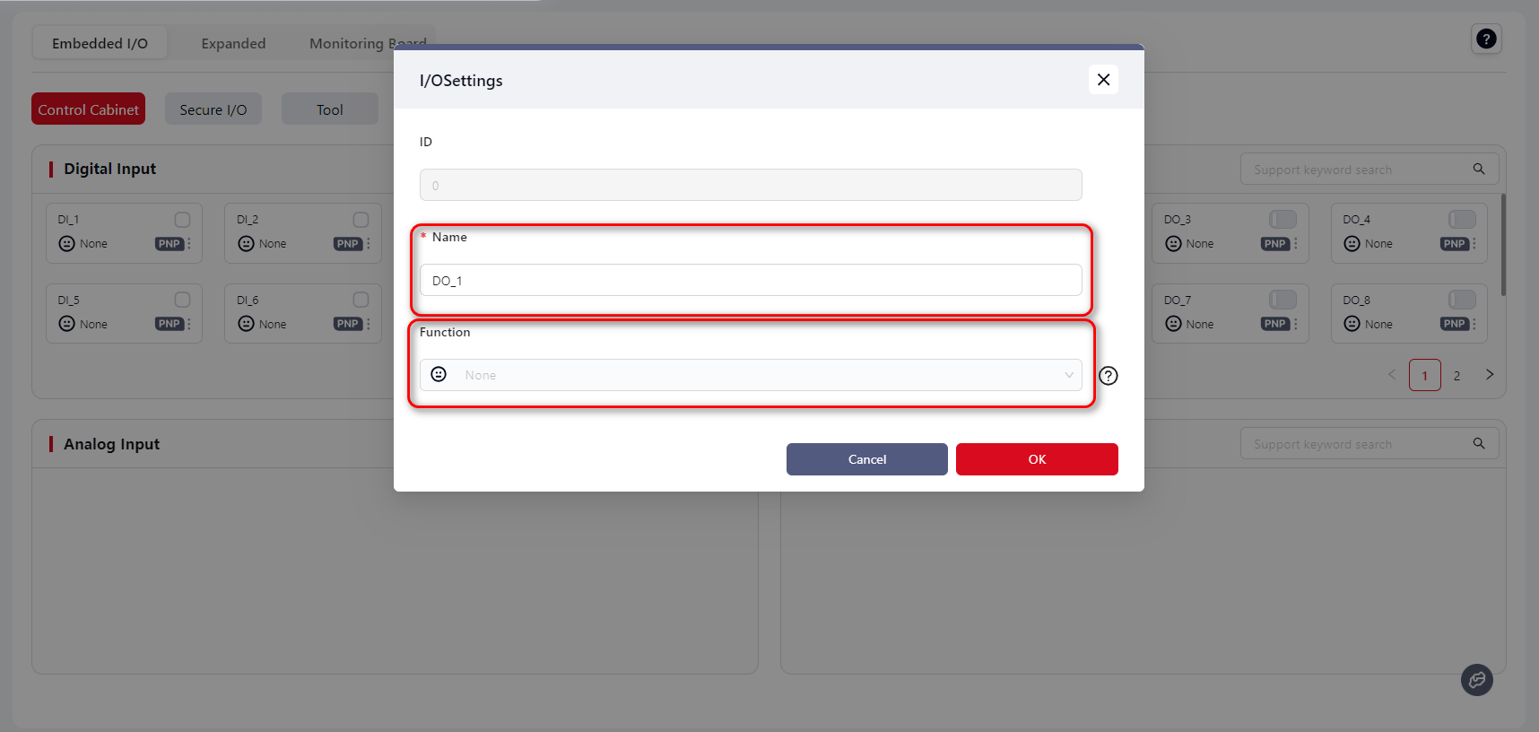
Edit the DO name under Name, and select its function under Function.
After confirmation, the DO reflects the real-time state of the bound system signal.
Currently supported DO states are shown below:
| Icon | Robot State | Description | Signal |
|---|---|---|---|
| None | No function | None |
 | Idle | Robot is not running a program. | High |
| Program Paused | The open program is paused. | High |
| Program Running | The open program is running. | High |
 | Error | Robot collision alarm triggered. | High |
 | Powered On | Robot is powered on. | High |
| Enabled | Robot is enabled. | High |
 | In Motion | Robot is moving (program, manual jog, or API control). | High |
 | Stationary | Robot is stationary (paused, stopped, ended, or waiting). | High |
| Cabinet On | Control cabinet is powered on. | High |
 | Emergency Stop | Robot stops, power off, disabled. | High |
| Speed Level 1 | Robot is in speed level 1 mode. | High |
| Speed Level 2 | Robot is in speed level 2 mode. | High |
| Protective Stop | Robot motion stopped. | High |
 | Safe Pose | Robot is at the safe pose defined in Settings – Safety Settings – Robot Pose. | High |
| Drag Mode | Robot is in drag mode. | High |
 | Collision | Robot collision occurred. | High |
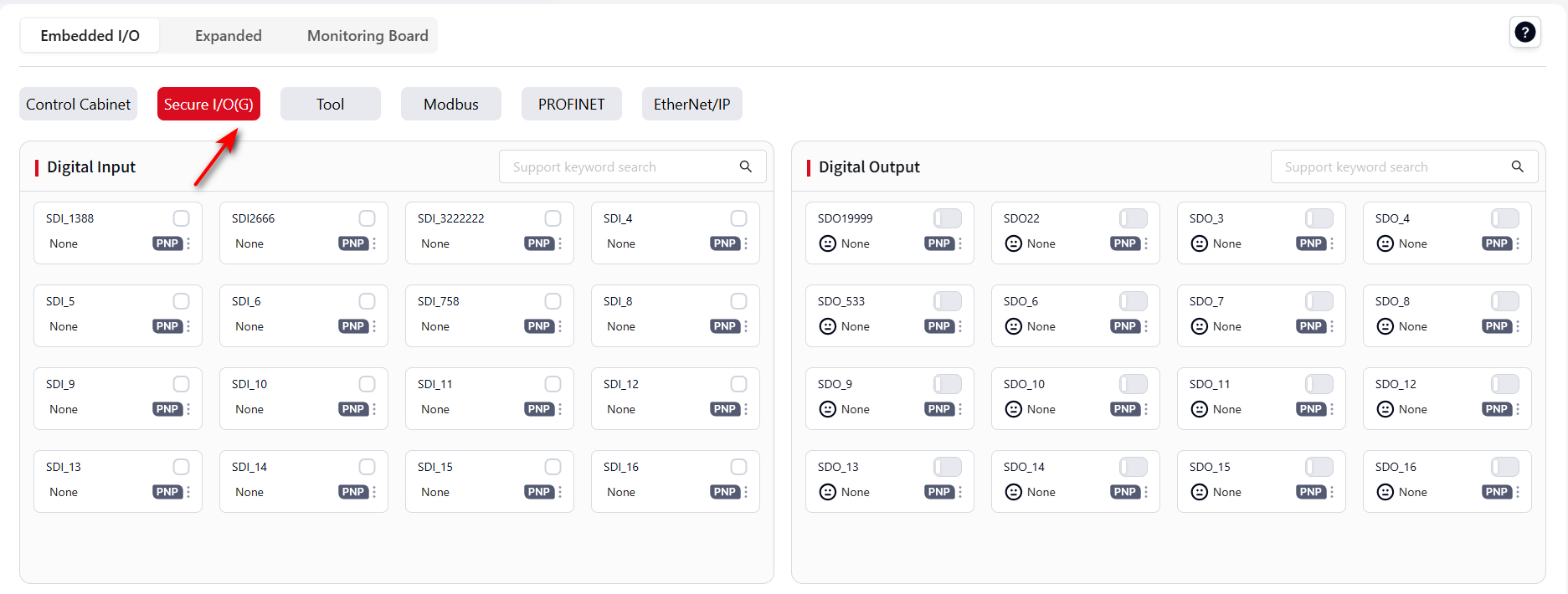
Safety I/O
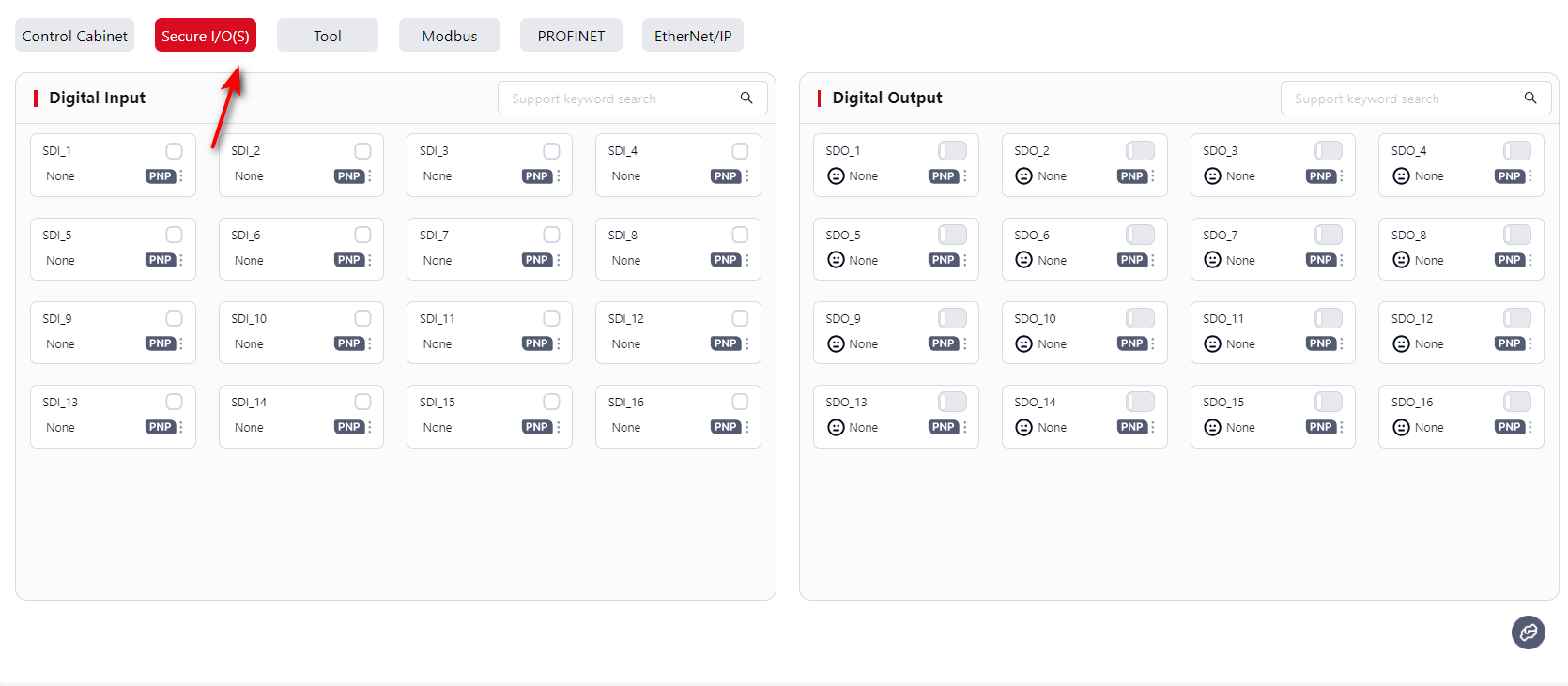
The control cabinet supports:
- 16 Safety DI (default: Safety mode, PNP)
- 16 Safety DO (default: Safety mode, PNP)
This page only displays the status of Safety I/O.
To configure, go to Settings - Safety Settings - Dedicated Safety I/O: Dedicated Safety I/O.
If it has been switch to General I/O, then the icon would be:
Tool End
The robot tool end TIO has two versions: V2 and V3. This section only describes how to use the V3 version. For other versions, please contact JAKA technical support team.
When using the tool end TIO, you can configure it under Settings - Hardware and Communication - Tool I/O, or directly operate it here.
The V3 tool end supports 2 digital inputs, 2 digital outputs, and 2 analog inputs.
The 2 digital outputs can be reused as a high-speed RS485 channel, and the 2 analog inputs can be reused as a low-speed RS485 channel.
Digital Input
The two DI channels can be set to different input modes: NPN input or PNP input.
After the TIO is powered on, both DI channels are configured as NPN inputs by default.
Configuration method is the same as Cabinet Digital Input.
Digital Output
The two DO channels can be reused as RS485 channel pins.
When used as DO, each can be set to different output modes such as NPN output, PNP output, or push-pull output.
After the TIO is powered on, both DO channels are configured as NPN outputs by default.
Configuration method is the same as Cabinet Digital Output.
Note:
When the 2 DO channels are used as RS485, they must both be set to RS485 Channel 1 mode.
If one DO is changed to RS485 Channel 1, the other will also switch to RS485 Channel 1.
If one DO is changed from RS485 Channel 1 to another mode, the other will automatically switch to NPN output mode.
Analog Input
The TIO provides two multiplexed analog input channels, which can also be reused as RS485 Channel 2.
After the TIO is powered on, both channels are used as analog inputs by default.
Voltage range: 0–10V
Display range: 0–4096
Mapping: 0V = 0, 10V = 4096
Resolution: 0.1V
Note:
The AI value is never exactly 0, even if no external device is connected.
When TIO is not connected to external devices, the displayed value depends on the TIO board model, typically around 400–500 or 700–800.
Modbus
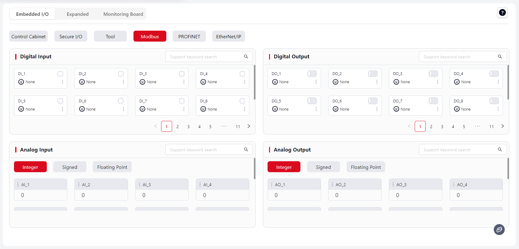
The JAKA robot control cabinet supports the Modbus protocol. It can act as a Modbus slave to communicate with external devices.
The Modbus window displays I/O signals accessible via Modbus. As a Modbus device, the controller supports:
- 128 Digital Inputs, 128 Digital Outputs.
- 16 Integer Analog Inputs, 16 Integer Analog Outputs.
- 16 Signed Analog Inputs, 16 Signed Analog Outputs.
- 32 Float Analog Inputs, 32 Float Analog Outputs.
For Modbus register address definitions, see: Modbus I/O Address Table.
For PLC communication setup, see JAKA Communication Manual.
Digital Input (DI) / Output (DO)
The DI/DO interface allows monitoring of Modbus digital input states.
- DI: When triggered, the assigned function is executed.
- DO: Displays the status of the assigned function in real time.
Supported functions and setup methods are the same as Cabinet Digital Input and Cabinet Digital Output.
Analog Input (AI) / Output (AO)
The AI/AO interface allows monitoring of Modbus analog signals.
Modbus values are single-precision floats with 7 significant digits. Values exceeding this will be rounded.
Setup method is the same as above.
PROFINET
Tip:
PROFINET and EtherNet/IP must first be enabled under Settings - Hardware and Communication - PROFINET Settings or EtherNet/IP Settings before they appear in the I/O Panel.
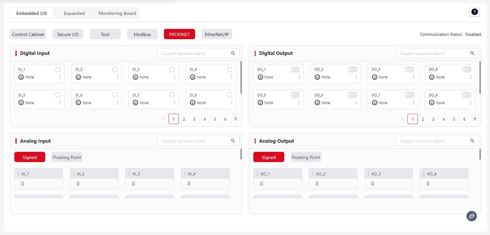
The control cabinet supports PROFINET protocol and can act as a PROFINET I/O slave to communicate with external devices.
The PROFINET window displays I/O signals accessible via PROFINET. As a PROFINET device, the controller supports:
- 64 Digital Inputs, 64 Digital Outputs
- 32 Signed Analog Inputs, 32 Signed Analog Outputs
- 32 Float Analog Inputs, 32 Float Analog Outputs
For PROFINET register address definitions, see: PROFINET I/O Address Table.
For GSDML–XML device description files, please contact JAKA support.
For PLC communication setup, see JAKA Communication Manual.
Configuration of DI, DO, AI, AO is the same as for Modbus.
EtherNet/IP
The control cabinet supports the EtherNet/IP protocol and can act as an “adapter” to communicate with external devices.
The EtherNet/IP window displays I/O signals accessible via EtherNet/IP. As an EtherNet/IP device, the controller supports:
- 64 Digital Inputs, 64 Digital Outputs
- 24 Signed Analog Inputs, 24 Signed Analog Outputs
- 24 Float Analog Inputs, 24 Float Analog Outputs
For EtherNet/IP register address definitions, see: EtherNet/IP I/O Address Table.
For EDS device description files, please contact JAKA support.
For PLC communication setup, see JAKA Communication Manual.
Configuration of DI, DO, AI, AO is the same as for Modbus.
Extended I/O
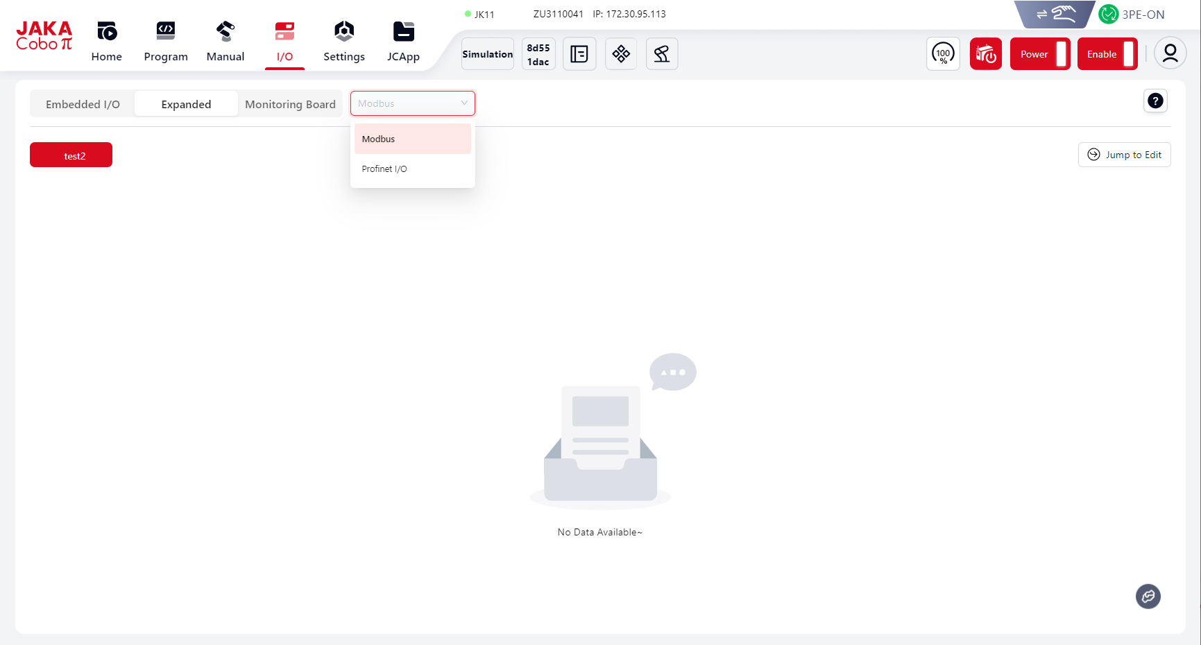
Modbus
Extended I/O supports Modbus TCP/IP and Modbus RTU.
Here, users can view the configured Modbus slave information and status:
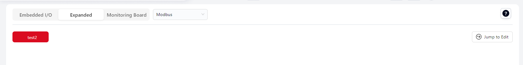
For configuration, click Edit, and the system will automatically jump to Settings - Hardware & Communication - Modbus Settings - Slave Management. Click Add to configure.
PROFINET
Here, users can view the configured PROFINET slave information and status:
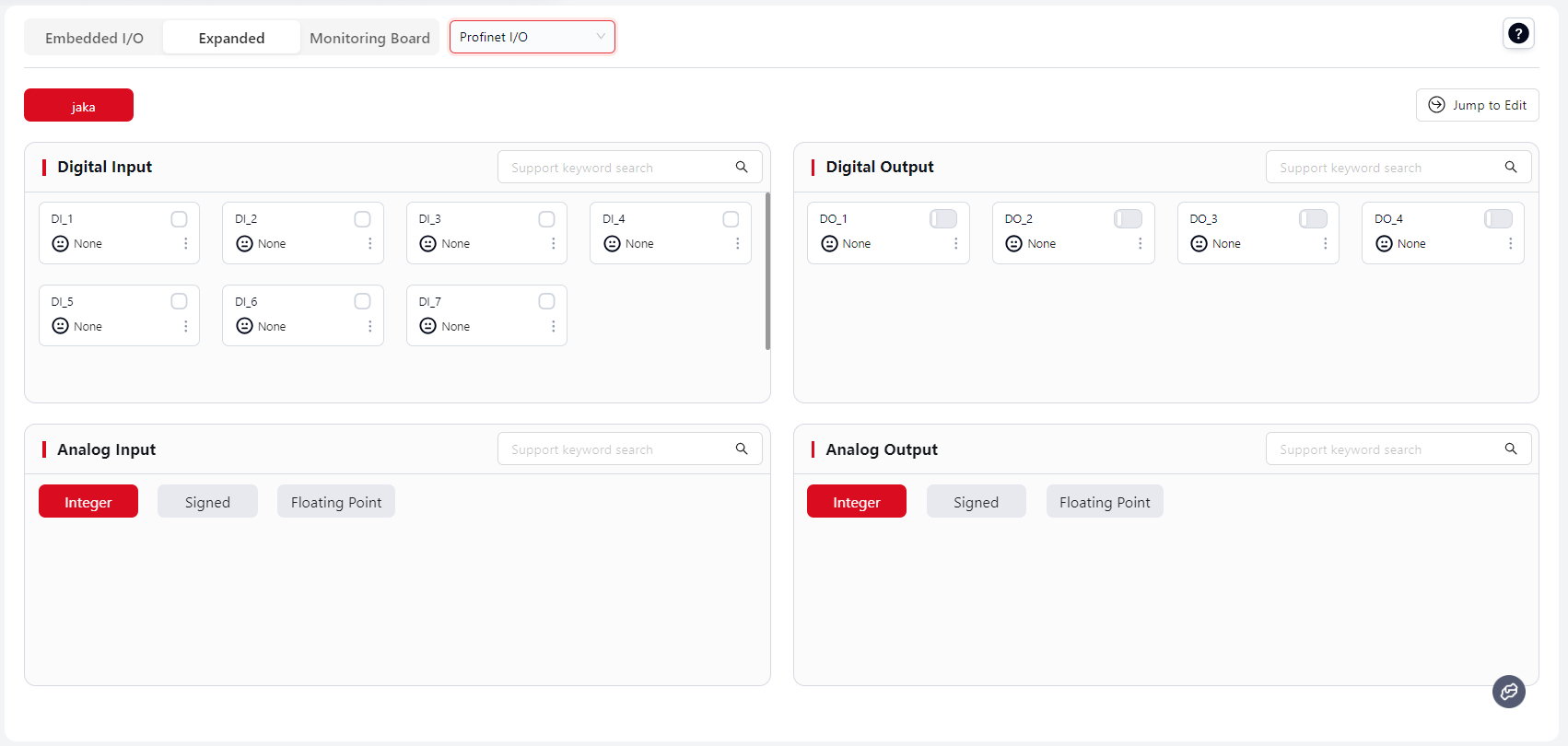
For configuration, click Edit, and the system will automatically jump to Settings - Hardware & Communication - Extended Communication.
Tip:
The number of configured slaves under Settings - Extended Communication determines how many slave cards are displayed here.
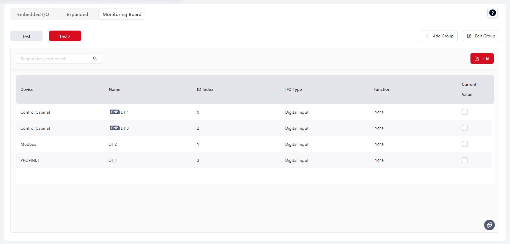
Monitor Board
Users can add existing Fixed I/O and Extended I/O here for unified monitoring while running programs.
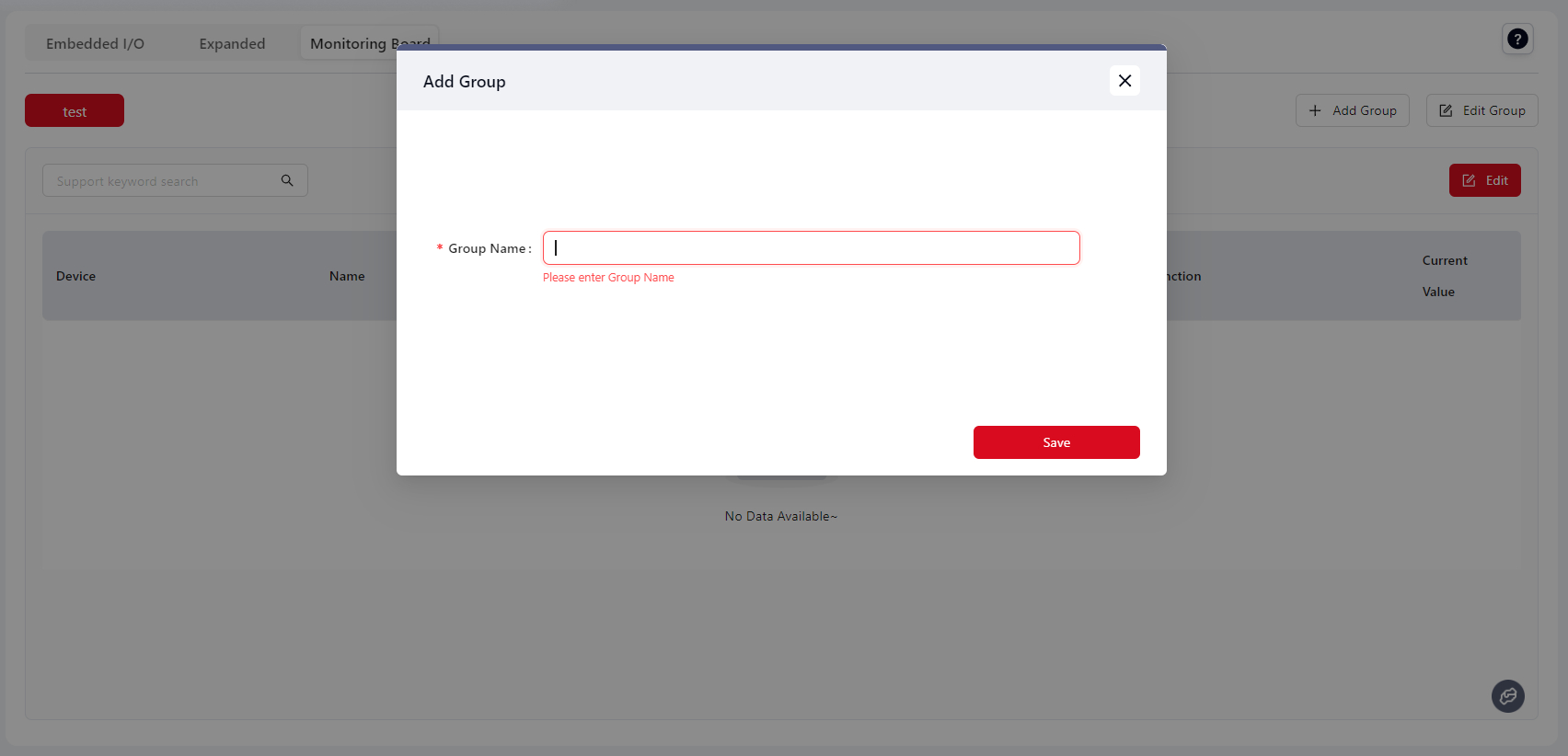
Steps:
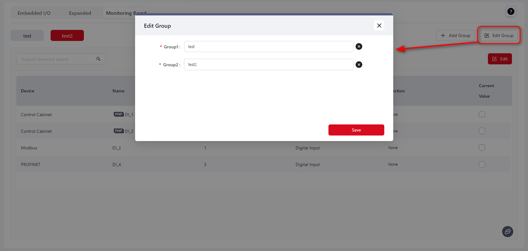
- Click
Add Group
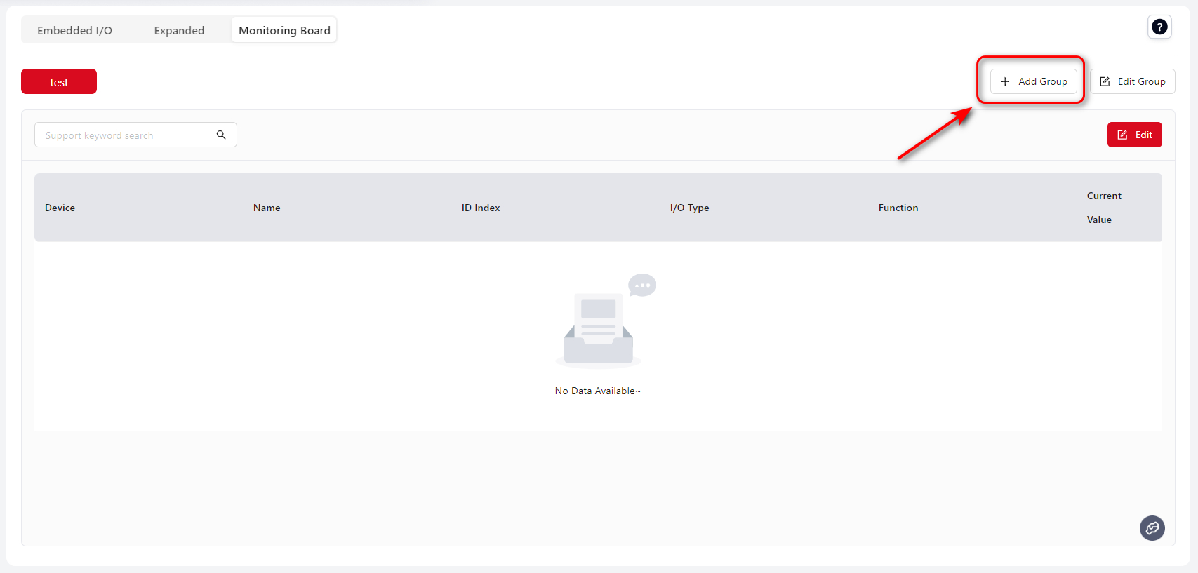
- Enter
Group Nameand clickSave
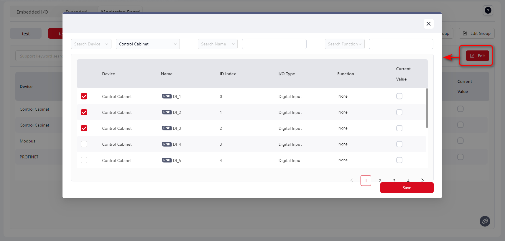
- The saved group will appear in the top left. Click
Edit
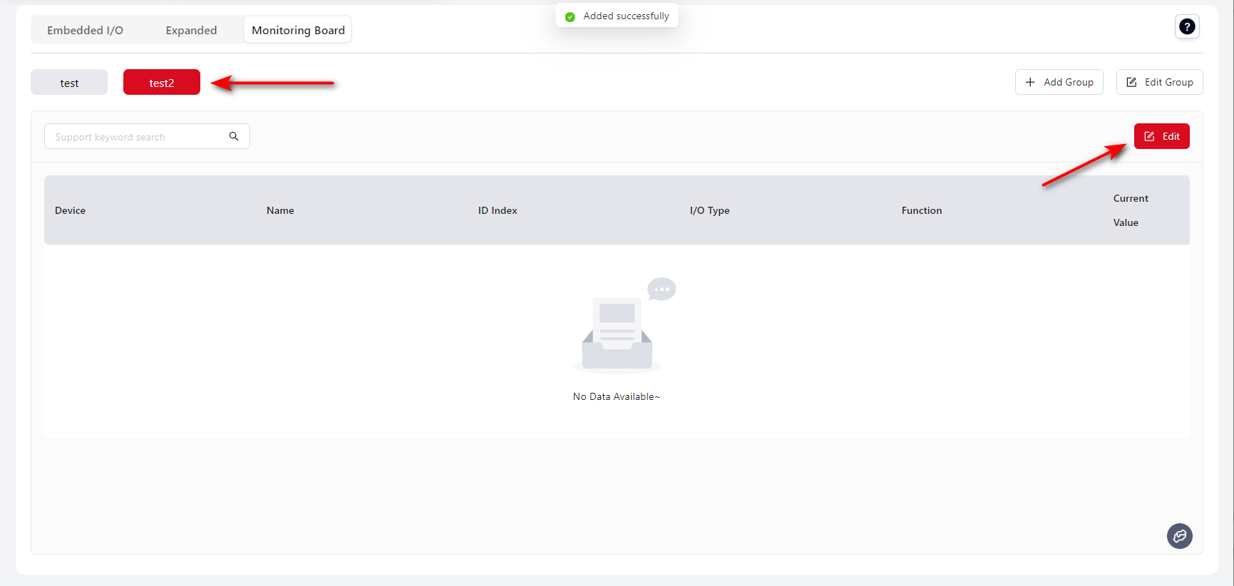
- In the popup, select the required I/O
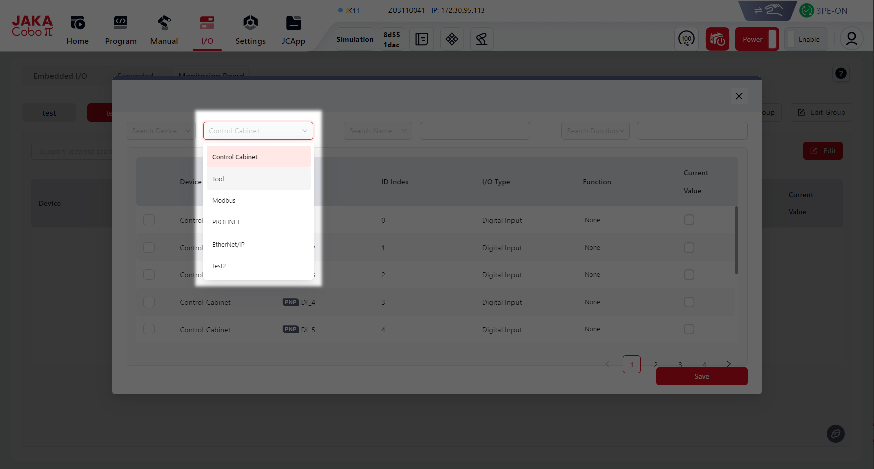
You can choose the device type in the Device dropdown, or search by keyword in Name or Function.
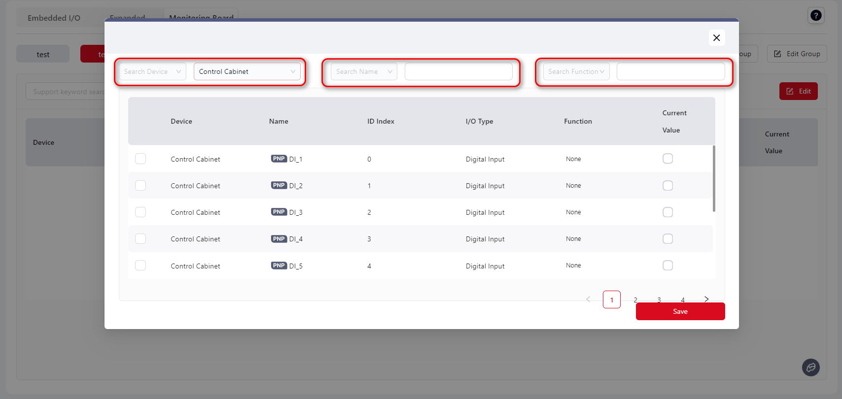
- Select the required I/O and click
Save
Tip:
I/O from different devices can be selected at the same time.
- After saving, all selected I/O will belong to the same group and be displayed on the same page.
- Click
Editto deselect I/O items
- Click
Edit Groupto rename or delete the group
- The configured Monitor Board can also be viewed under the
Programmingpage.