Manual
Manual
Interface Overview
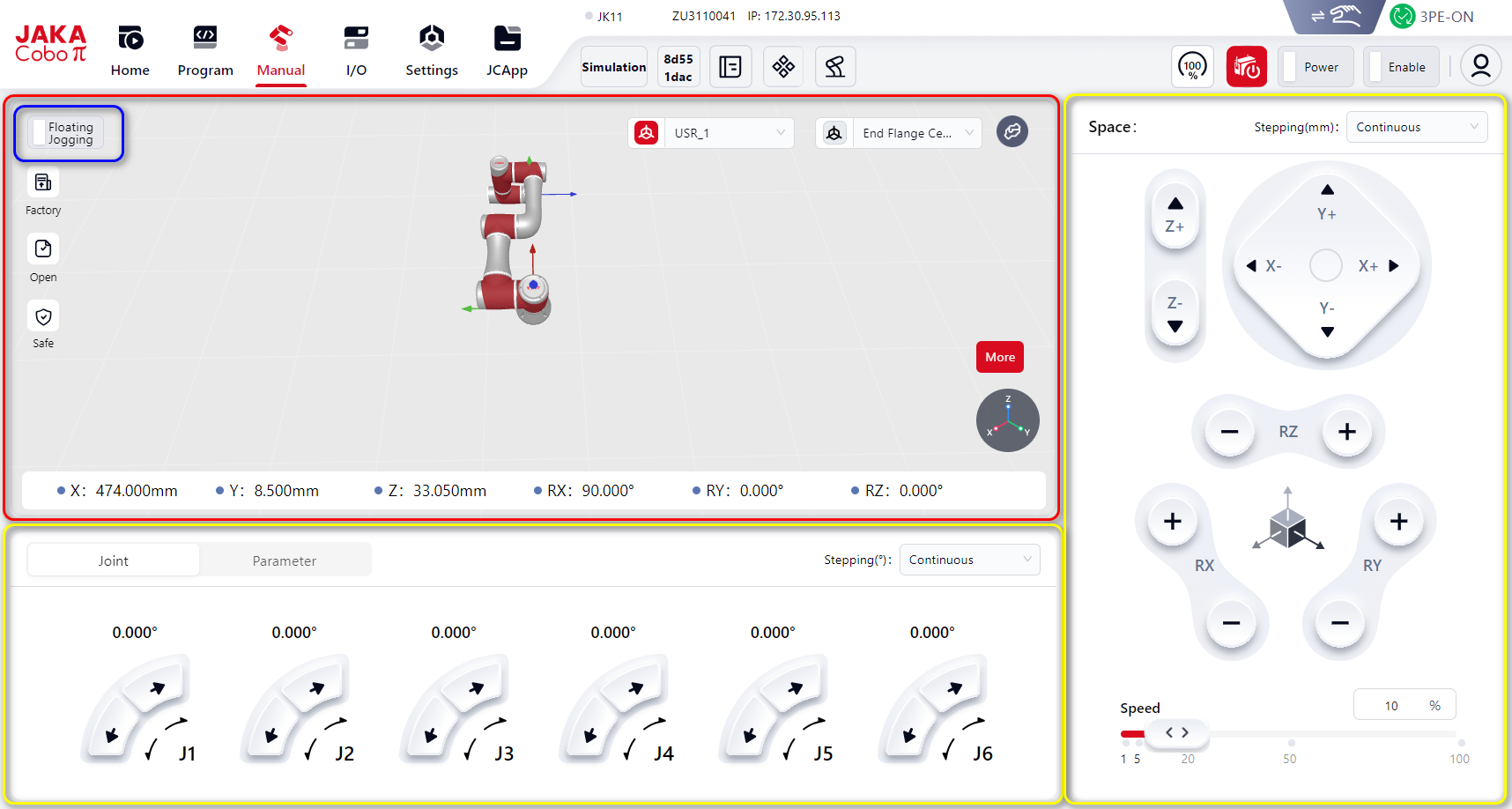
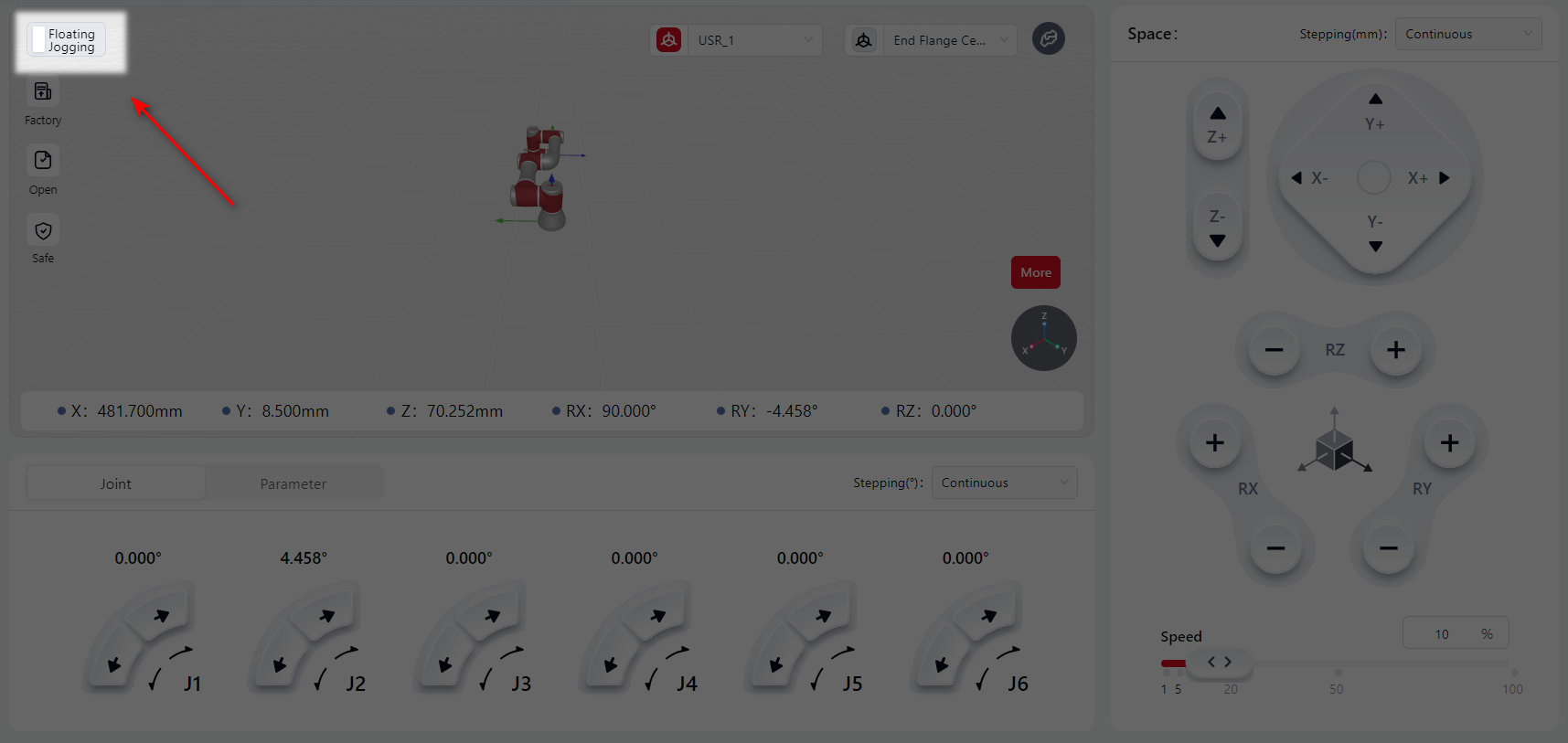
As shown above, the manual interface is divided into three functional areas:
Red box: Simulation model area.
Blue box: Floating Jogging function button. Click to enter floating jogging mode.
Yellow box: Operation area.
Details are described below:
Simulation Model Area
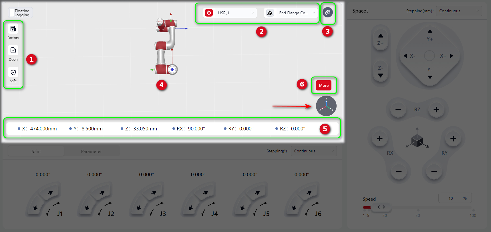
Pose Quick Reset Button
At 1 is the pose quick reset button. Press and hold to restore the robot to the corresponding pose.
When pressed, the button turns red and the robot moves automatically. Movement stops when the pose is reached.
Coordinate System Switching
At 2, click the drop-down menu to switch the coordinate system used for Cartesian JOG motion between World (User) coordinate system and Tool coordinate system (flange center).
When the icon is red, the selected coordinate system is active.
Help Button
At 3 is the Help button. For details, see: Help Button
Simulation Model Display Area
At 4 is the 3D simulation model display area. The model is consistent with the connected real robot or virtual robot and reflects its actual or simulated motion in real time.
Zoom view: Hover the mouse in the area and scroll the wheel to zoom in/out.
Rotate view: Hover the mouse, hold the left button and drag to rotate the view for 360° observation.
Axis indication: The circular icon at the bottom right shows X, Y, Z colors for easy reference.
Parameter Display Area
At 5 is the parameter display area, showing the robot’s pose of the tool coordinate system in the world (user) coordinate system.
Backdrive Mode
In this mode, the robot joint brakes are released, allowing the joints to be moved with minimal force.
In collision scenarios, the reverse drive feature enables selective release of specific joint brakes under robot-enabled status, moving the joint to the target position without releasing all robot brakes.
At 6, click More, and the operation buttons will appear:
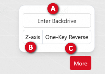
Press and hold Backdrive , and the robot enters reverse drive mode. Users can drag the desired joint to force its movement.
Note:
The robot must be powered on and in an enabled state to enter reverse drive mode.
If the joint movement speed exceeds 50°/s during reverse drive mode, the system will exit reverse drive mode due to overspeed detection.
Warnings:
When the robot is in reverse drive mode, the released joint may rapidly fall due to gravity. Ensure effective support for the robot and any attached tools or workpieces before releasing the brakes.
One-Key Pose Adjustment
One-key pose adjustment quickly aligns the end flange to a target orientation.
- At
6, clickMoreto show buttons:
At B, select X/Y/Z axis.
At C, choose One-Key Reverse or One-Key Forward. Hold to adjust the flange orientation relative to the selected axis.
Explanation:
X/Y/Zaxis: Axes of both the reference and flange coordinate systems.One-Key Reverse: The selected axis direction is opposite between reference and flange coordinate system.One-Key Forward: The selected axis direction is the same between reference and flange coordinate system.
Operation Area
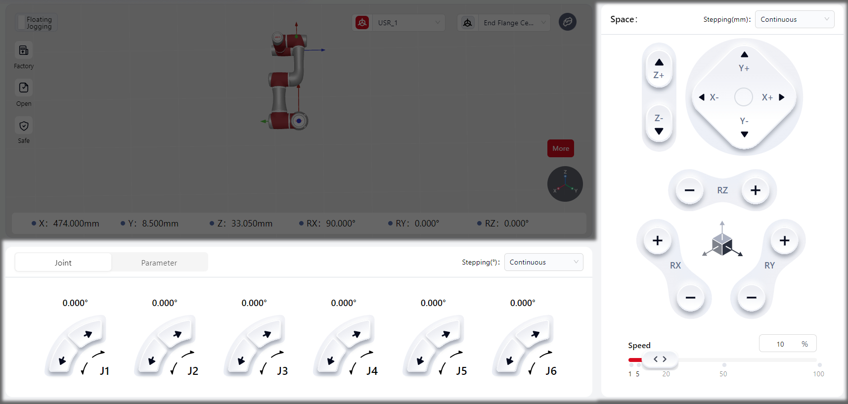
Joint Adjustment
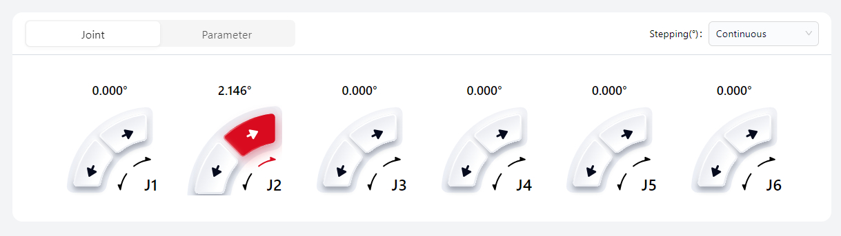
Joint: Control each joint independently in step or continuous motion.
Press or hold the virtual joystick. When active, it turns red, indicating motion.
Release it. It turns gray, and the robot stops immediately.
You can set at stepping for user-define motion or continuous motion, or a specific value.
Parameter Adjustment
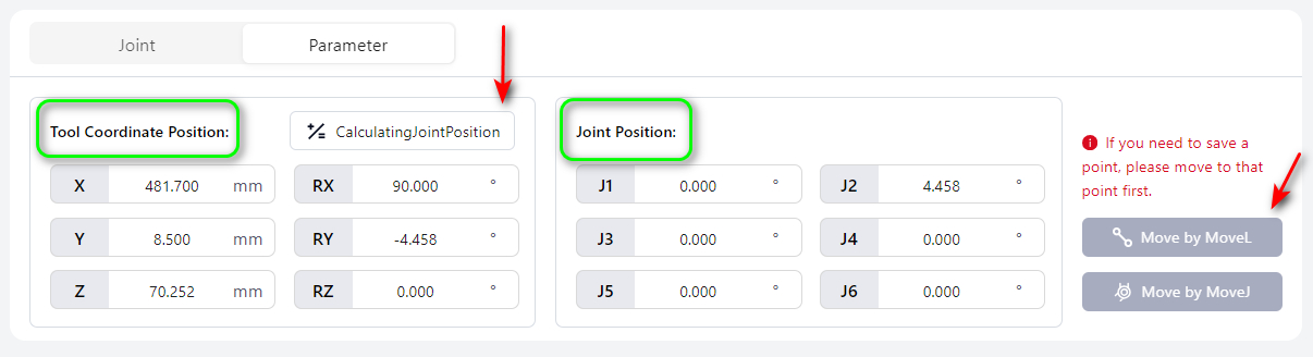
Method 1: Enter axis values at Tool Coordinate Position, click Calculating Joint Position, then hold Move by MoveL or Move by MoveJ. The robot moves to the specified point and stops automatically.
Note:
When setting Tool Coordinate Position, make sure to set the coordinate system.
Method 2: Enter joint values at Joint Position, then hold Move by MoveL or Move by MoveJ. The robot moves to the specified point and stops automatically.
Cartesian Adjustment
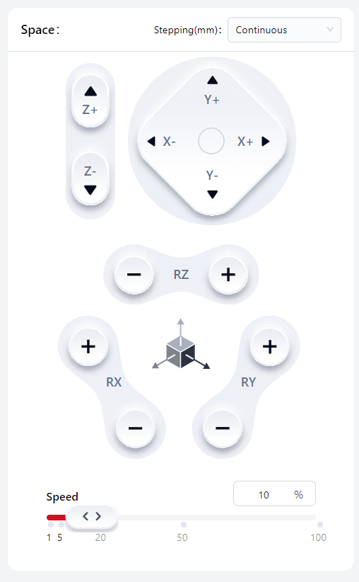
Cartesian adjustment controls the robot's tool coordinate origin point in the world (user) coordinate system.
Hold the virtual joystick → red = active, robot moves.
Release joystick → gray = inactive, robot stops.
You can set at stepping for user-define motion or continuous motion, or a specific value, and adjust the robot's moving speed at Speed.
Note:
This speed setting applies only in manual mode.
External Axis Adjustment
When an external axis is connected, the External Axis Adjustment page will be displayed. On this page, the user can manually control the movement of the external axis.
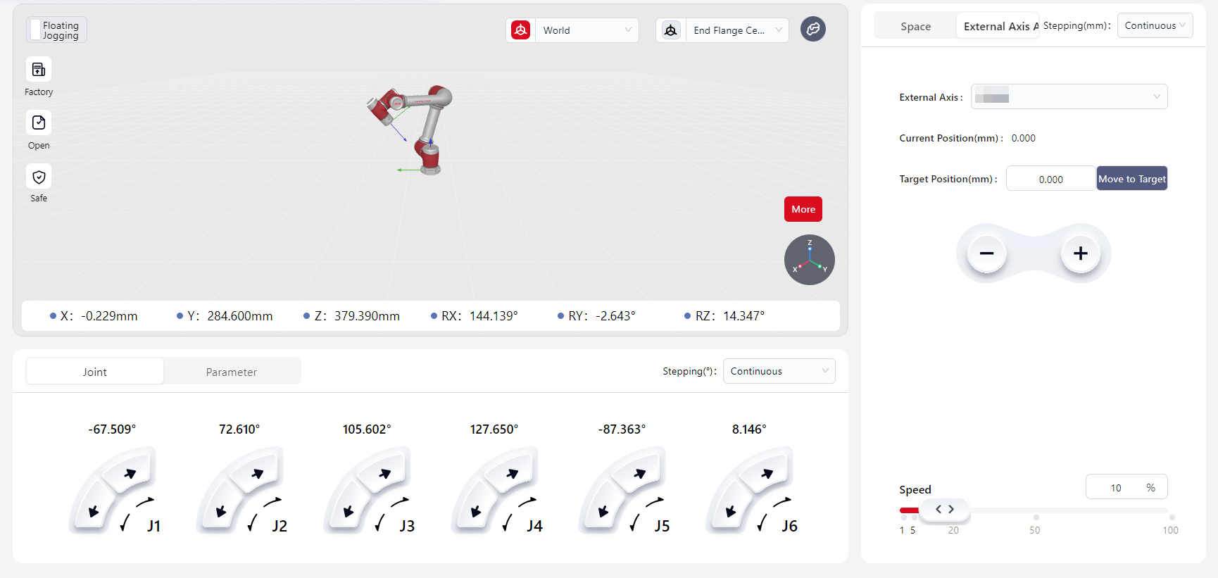
External Axis– Allows the user to select from the list of external axes that have been configured and added to the management list.Current Position– Displays the real-time position of the selected external axis.Target Position– The desired position to which the external axis should move.Move to Target– Press and hold to move the external axis to the user-defined target position.-/+– Moves the external axis in the negative or positive direction.Speed– Adjusts the jogging speed percentage of the external axis. The default value is 10%.
Floating Jogging
Click this button to enter floating jogging mode.
Note:
World and tool coordinate system settings still apply in floating jogging mode.
Interface Overview
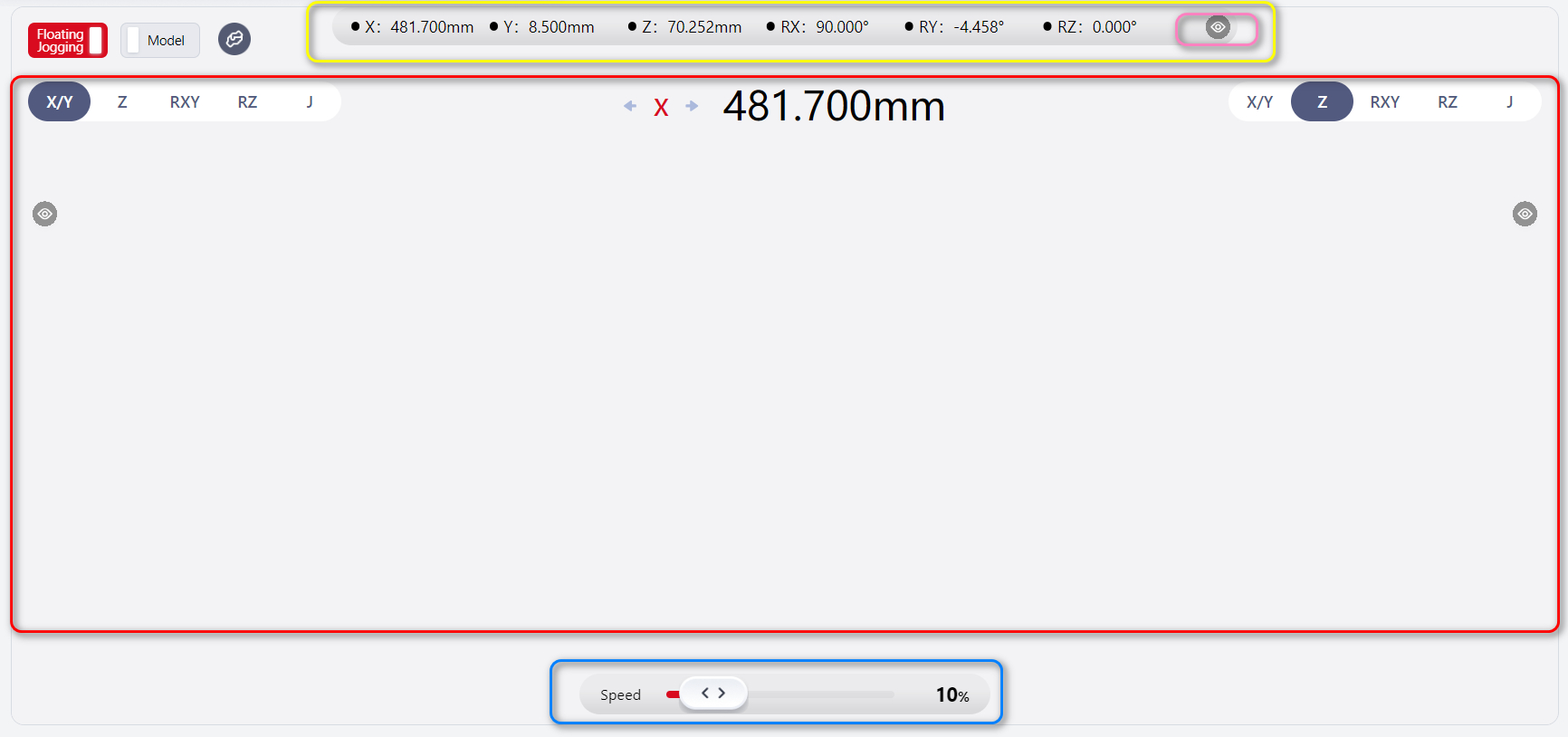
The floating jogging interface has three functional areas:
Yellow box: Pose parameters
Blue box: Speed adjustment
Red box: Joystick control
Pose Parameters
Displays real-time pose data. Click the eye icon in the pink box to hide or show parameters.
Speed Adjustment
Drag the slider to adjust robot speed. Default speed: 10%.
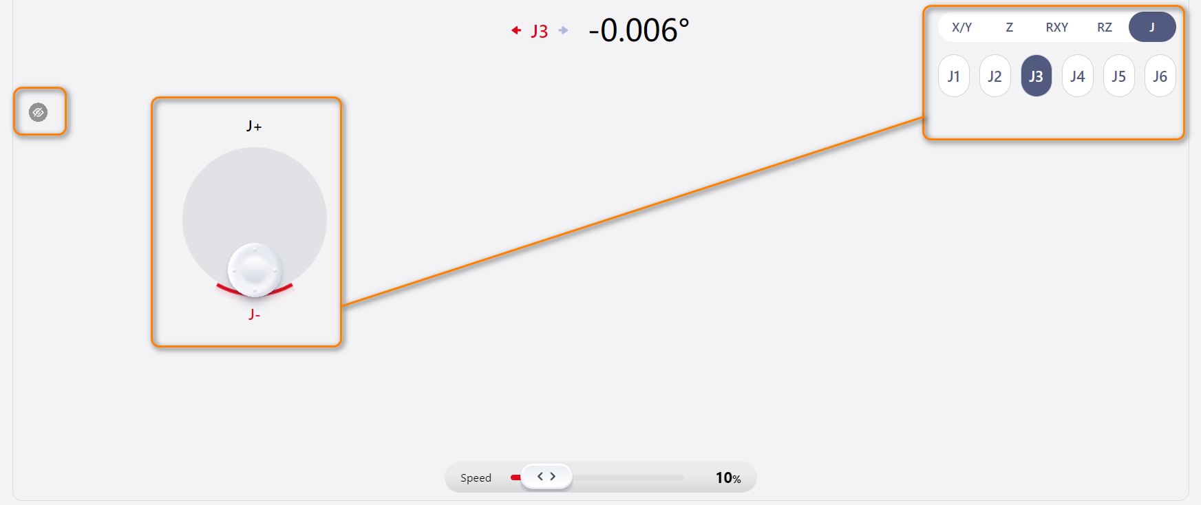
Joystick Control
- In the green box, select
X/Y,Z,RXY,RZ, orZ.
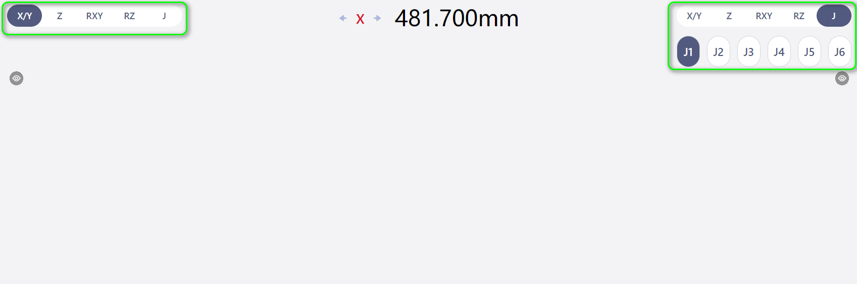
- Click blank space to show joystick. It follows the selected axis directions.
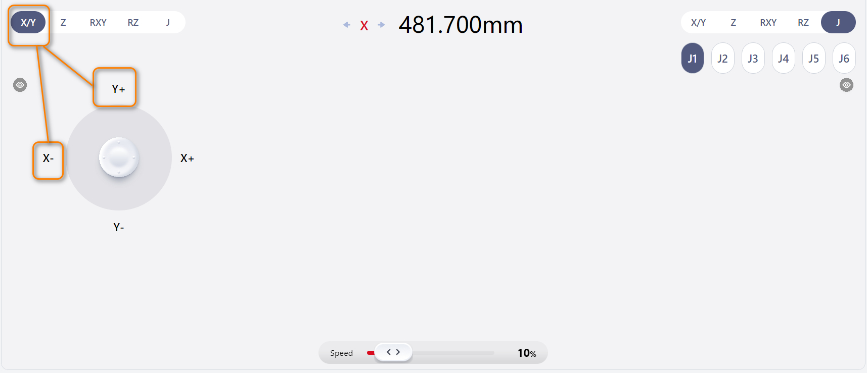
- Hold and move mouse to control robot. Motion direction and values are displayed at the top.
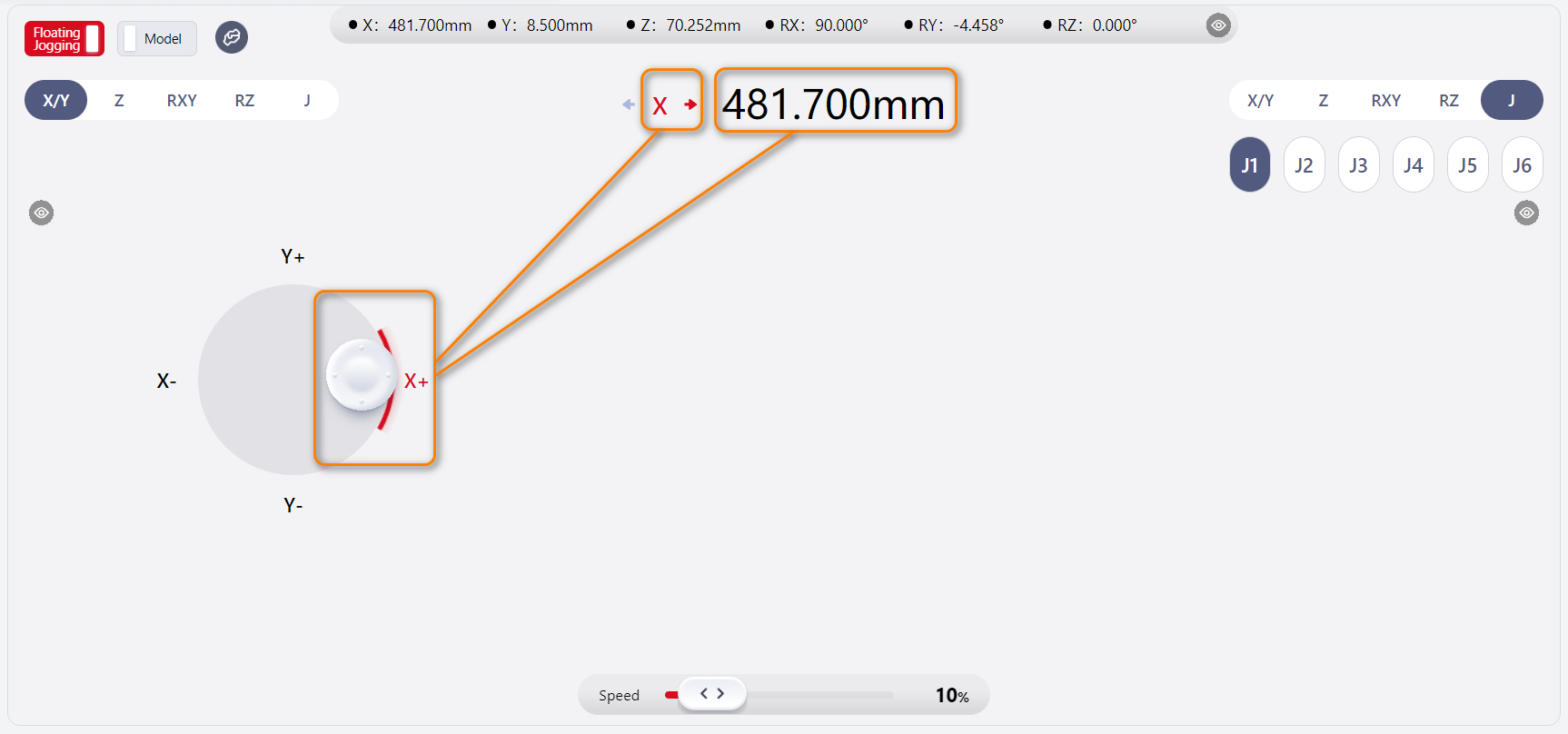
- Release to hide joystick and stop motion.
Note:
Left and right sides work the same.
If one side’s eye icon is clicked, that side’s joystick and axis selection are hidden. The other side controls the page.
Caution:
Left and right sides cannot be operated simultaneously.
Display Model
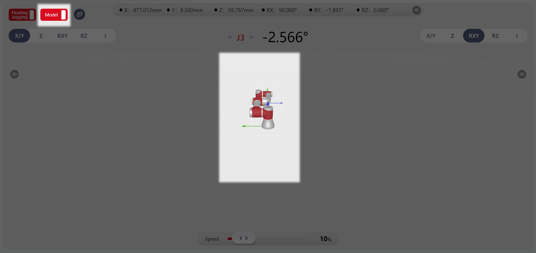
Click Model at the top left to show the 3D robot model, which is consistent with the real/virtual robot.
Model display does not affect joystick operation.
View adjustment is the same as Simulation Model Display TBA.
Force Control
Tips
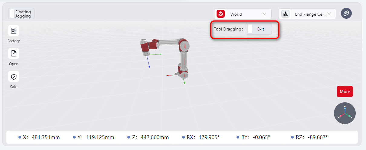
JAKA robots can be used with end sensors.
When connected, the Tool Dragging option appears in the manual interface.
Note:
- Before enabling
tool dragging, ensure that the robot's load has been set correctly. - Before configuring direction, feel, rebound, and other parameters, ensure that tool dragging mode is turned off.
- After enabling
tool dragging, the system will check the force values from the sensor. If they exceed 3 N or 0.2 Nm (indicating external force), a popup will prompt you to confirm whether you still want to enable tool dragging. Verify if there is actual external force; if so, clickConfirmto proceed. If no external force is detected, the sensor's zero point might have shifted. In this case, clickCancelto go to the force display window and calibrate the sensor.
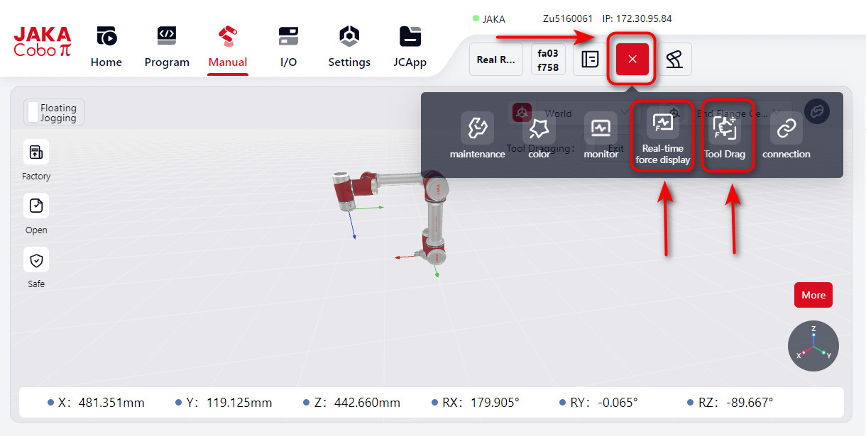
Real-Time Force Display
You can view the robot's real-time data by selecting Real-time Force Display from the top navigation bar. Clicking it will open a page that shows the current contact force values in real time.
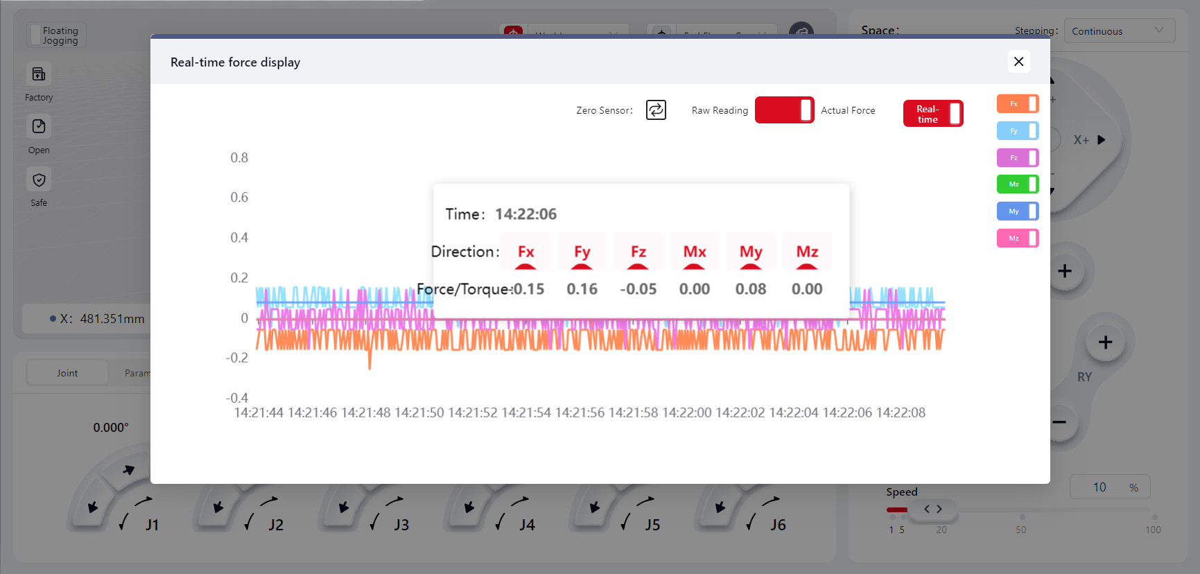
You can toggle the switches for Fx, Fy, Fz, Mx, My, and Mz to display the corresponding force data curves.
When the Real-time toggle is on, the force curve will continuously refresh. When off, the curve will stop refreshing, and it will display the last recorded force curve. Click on any point on the curve to see the recorded force data at that moment.
Tool Dragging
Click on Tool Dragging to enter the configuration interface where you can set various parameters and options:
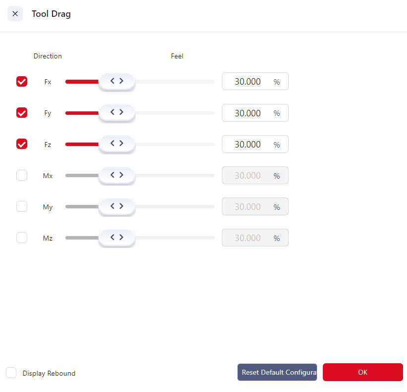
Direction
Fx, Fy, Fz correspond to displacements along the X, Y, and Z axes, while Mx, My, Mz correspond to rotations around the X, Y, and Z axes.
You can select one or more directions, and once tool dragging is enabled, the robot can be dragged along the selected direction(s).
Feel
The feel setting determines the force required to move the robot in Tool Dragging mode. The harder the feel setting, the greater the force needed to drag the robot. Fx, Fy, and Fz correspond to displacements along the X, Y, and Z axes, while Mx, My, and Mz correspond to rotations around these axes. When the checkbox for a specific direction is selected, the feel slider for that direction turns red. Adjust the slider to modify the feel stiffness, and click "Confirm" to enable dragging the robot in that direction.
The default feel setting is 30%.
Rebound
The rebound setting allows the robot to simulate a spring effect: the further the robot moves from its starting point, the greater the force required to drag it, and upon release, the robot will return to its initial position before dragging.
A higher rebound value increases the force needed to drag the robot and the speed at which it rebounds upon release.
Enter a rebound value in the input box and click "Confirm" to activate the rebound function. The default rebound value is 0, and the maximum value is 100.
Select the Show Rebound Values checkbox to display a list of rebound data.
Warning:
- After the device is installed, upon restarting the robot, recovering from a fault, or after the sensor has been powered on for an extended period, it is recommended to set the feel stiffness to a harder setting. Test to confirm there are no faults before adjusting to the desired level.
- Adjust the feel setting based on practical needs. Overly soft settings may make the robot too sensitive, potentially leading to excessive speed and acceleration under external forces, which could compromise overall system stability.
S Series
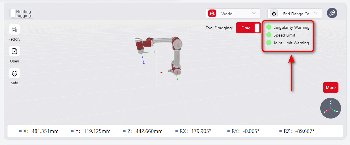
When the S-series robot enters Tool Dragging mode, the Tool Dragging switch on the manual operation interface is activated, displaying singularity warnings, speed limits, and joint soft limit status indicators.
When a limit is triggered, the indicator light on the manual operation interface turns red, and a red halo appears around the affected joint.
As the robot approaches a singularity or joint soft limit, the dragging feel becomes progressively harder. However, moving away from the limit will not be affected. Meanwhile, the robot’s end ring indicator flashes red and yellow.
The singularity warning range for dragging can be set in the Force Control Configuration - Advanced Feature Configurationinterface. Refer to the JAKA S-Series Hardware User Manual for singularity positions.
When the TCP dragging speed at the robot’s end reaches the limit, it will be capped, preventing further acceleration. The robot's end ring indicator will flash red and yellow.
The force control speed limit can be set in the Force Control Configuration - Advanced Feature Configuration interface.
Warning:
Avoid enabling Tool Dragging in postures that are very close to singularities or joint limits, as these postures may exceed the allowable range for Tool Dragging. Due to safety restrictions, the robot cannot be dragged even if Tool Dragging is enabled.
In such cases, move away from singularities or joint limit postures using joint motion before enabling Tool Dragging.