JAKA TCP/IP Control Protocol
JAKA TCP/IP Control Protocol
Document Description
JAKA supports an external control protocol based on TCP/IP. This protocol provides a rich set of interfaces, enabling customers to control the robot and obtain information through them. It is also one of the core communication protocols of the JAKA SDK.
Version Description
This TCP/IP control protocol document is currently mainly adapted for controller versions V3. Some interfaces may have compatibility issues between the two controllers, and these are marked.
Framework Basics
JAKA TCP/IP Protocol Communication Framework
The interaction framework defined by the JAKA TCP/IP control protocol is as follows:
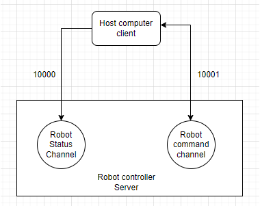
A TCP server runs in the robot controller to accept user-defined commands and return status data. This server uses ports 10000 and 10001 to interact with external clients, where:
- 10001 — used to send control commands to the robot and receive responses from the controller;
- 10000 — used to receive data returned by the robot (users can define the sending frequency and data content).
Users can carry out secondary development for the robot based on the JAKA TCP/IP protocol, and during development must note:
- TCP/IP commands are executed asynchronously; the returned information only indicates that the controller has received the command, completed preprocessing and forwarding, and does not reflect the final execution result of the command. Some commands’ execution results require actively querying feedback data to obtain them;
- Users need to implement the corresponding TCP client calls in accordance with this protocol, i.e., they must design the upper-level planner themselves to send robot data (servo_j, servo_p);
- This function can be used simultaneously with the JAKA App without disconnecting the App from the controller. However, users must ensure that only one client can connect to port 10001; otherwise, the latter client may immediately replace the former.
Communication Port Data Description
Data sent from port 10001 and received from port 10000 is defined in JSON format. Users can quickly construct commands or parse feedback data according to the protocol.
Port 10001 Description
All commands in this manual fall into this category. All robot control commands are based on port 10001, and the port interaction data format is defined as follows:
- Message sending format:
{"cmdName":"cmd","parameter1":"parameter2","parameter3":"parameter4",...}
- Message receiving format:
{"cmdName":"cmd","errorCode":"0","errorMsg":"","parameter1":"parameter2","parameter3":"parameter4",...}
Port 10000 description
Port 10000 will return robot-related data in string format. The returned content can be referenced from the following example:
Example:
{
    "len":Int,
    "drag_status":Bool,
    "extio":Object{...},
    "errcode":"0x0",
    "errmsg":"",
    "monitor_data":Array[6],
    "torqsensor":Array[2],
    "joint_actual_position":Array[6],
    "joint_position":Array[6],
    "actual_position":Array[6],
    "position":Array[6],
    "din":Array[144],
    "dout":Array[144],
    "ain":Array[66],
    "aout":Array[66],
    "tio_key":Array[3],
    "tio_din":Array[8],
    "tio_dout":Array[8],
    "tio_ain":Array[1],
    "task_state":Int,
    "homed":Array[9],
    "task_mode":Int,
    "interp_state":Int,
    "enabled":Bool,
    "paused":Bool,
    "rapidrate":Int,
    "current_tool_id":Int,
    "current_user_id":Int,
    "on_soft_limit":Int,
    "emergency_stop":Int,
    "drag_near_limit":Array[6],
    "funcdi":Array[15],
    "powered_on":Int,
    "inpos":Bool,
    "motion_mode":Int,
    "curr_tcp_trans_vel":Int,
    "protective_stop":Int,
    "point_key":Int,
    "netState":Int
}
Description:
- len: The length of the data packet, generally not exceeding 15,000 bytes (depending on the data content).
- drag_status: Boolean value indicating whether it is in drag mode.
- extio: Configuration and status of the extended IO module, with the internal data structure as follows—
- status: Status of all extended IO pins, including DI, DO, AI, AO.
- status[0]: Status of all extended DI
- status[1]: Status of all extended DO
- status[2]: Status of all extended AI
- status[3]: Status of all extended AO
- setup: Array of all extended IO configurations, up to 8. Each extended IO module’s settings should follow the structure below—
- setup[N][0]: Communication type. 0 represents Modbus RTU. 1 represents Modbus TCP/IP.
- setup[N][0]=0:
- setup[N][2][0]: Baud rate
- setup[N][2][1]: Data bit length
- setup[N][2][2]: Slave ID
- setup[N][2][3]: Data bits
- setup[N][2][4]: Parity bit
- setup[N][2][5]: Stop bit length
- setup[N][0]=1:
- setup[N][2][0]: IP address
- setup[N][2][1]: Port
- setup[N][2][2]: Slave ID
- setup[N][0]=0:
- setup[N][1]: Alias of the extended IO module.
- setup[N][2]: Communication configuration, depending on communication type.
- setup[N][0]: Communication type. 0 represents Modbus RTU. 1 represents Modbus TCP/IP.
- setup[N][3]: Pin configuration
- setup[N][3][0][0]: Starting offset of registers in DI
- setup[N][3][0][1]: [Number ]of DIs
- setup[N][3][1][0]: Starting offset of registers in DO
- setup[N][3][1][1]: [Number ]of DOs
- setup[N][3][2][0]: Starting offset of registers in AI
- setup[N][3][2][1]: Number of AIs
- setup[N][3][3][0]: Starting offset of registers in AO
- setup[N][3][3][1]: Number of AOs
- num: Extended IO module.
- pinmap: Pin diagram array of the extended IO module.
- pinmap[N][0]: Starting offset of registers in DI for [N]
- pinmap[N][1]: Starting offset of registers in DO for setup[N]
- pinmap[N][2]: Starting offset of []registers in AI for setup[N]
- pinmap[N][3]: Starting offset of [registers in AO ]for setup[N]
- mode: Status of the extended IO module. 0 means the status is ON, 1 means OFF.
- status: Status of all extended IO pins, including DI, DO, AI, AO.
- errcode: Hexadecimal string error code from the controller, such as "0x0".
- errmsg: Error message string from the controller, corresponding to errcode.
- monitor_data: Monitoring data of the robot and cabinet for diagnostics.
- monitor_data[0]: SCB major version number
- monitor_data[1]: SCB minor version number
- monitor_data[2]: Control cabinet temperature
- monitor_data[3]: Control cabinet bus average power
- monitor_data[4]: Control cabinet bus average current
- monitor_data[5]: Monitoring data of robot joints 1–6 in the array
- monitor_data[5][0]: Instantaneous current of robot joints
- monitor_data[5][1]: Instantaneous voltage of robot joints
- monitor_data[5][2]: Instantaneous temperature of robot joints
- monitor_data[5][3]: Instantaneous average power
- monitor_data[5][4]: Current fluctuation
- monitor_data[5][5]: Accumulated laps
- monitor_data[5][6]: Total operating time
- monitor_data[5][7]: Operating cycles since the last startup
- monitor_data[5][8]: Operating time since the last startup
- monitor_data[5][9]: Joint torque
- torqsensor: Torque settings and status array, data structure as follows—
- torqsensor[0]: Sensor ID
- torqsensor[1]: Current torque sensor settings
- torqsensor[1][0]: Sensor brand
- torqsensor[1][1]:Sensor pass filtering parameters
- torqsensor[1][2]: Sensor load settings mass[, x, y, z]
- torqsensor[1][3]: dead_zone_percent
- torqsensor[1][4]:force_field_comp_method
- torqsensor[1][5]: force_field_sample_no
- torqsensor[1][6]: sensor_payload_id
- torqsensor[1][7]: name of the sensor
- torqsensor[1][8]: delete_on_next_start
- torqsensor[1]: status of the torque sensor
- torqsensor[1][0]: torque sensor status. 1 means working, 0 means off.
- torqsensor[1][1]: torque sensor error code
- torqsensor[1][2]: actual contact force of the torque sensor (6 dimensions)
- torqsensor[1][3]: raw reading value of the torque sensor (6 dimensions)
- joint_actual_position: actual positions of all 6 joints. Usually refers to servo actual feedback position.
- joint_position: commanded positions of all 6 joints. (May have slight differences from the actual joint positions)
- actual_position: actual position of the robot TCP in Cartesian space.
- position: commanded position of the robot TCP in Cartesian space.
- din: array of all digital input values.
- dout: array of all digital output values in the cabinet.
- ain: array of all analog input values in the cabinet.
- aout: array of all analog output values in the cabinet.
- tio_din: array of the status of all tool digital inputs.
- tio_dout: array of the status of all tool digital outputs.
- tio_ain: array of the status of all tool analog inputs.
- task_state: indicator lights for power status and enable status. 1 means the robot is powered off, 2 means the robot is powered on, 3 means the robot is not enabled, 4 means the robot is enabled.
- homed: Home status of each joint (deprecated).
- task_mode: The robot's task mode. 1 means manual mode, 2 means automatic mode, 3 means reserved mode, 4 means drag mode.
- interp_state: Program status. 0 means idle, 1 means loading, 2 means paused, 3 means running.
- enabled: Boolean value showing whether the robot is enabled.
- paused: Boolean value showing whether the program is paused.
- rapidrate: Scaling rate of robot movement.
- current_tool_id: Index of the current TCP.
- current_user_id: Index of the current user coordinate system.
- on_soft_limit: Indicates whether it is at the soft limit, 0 means not reached, 1 means reached.
- emergency_stop: Indicates whether the emergency stop button is pressed, 0 means not pressed, 1 means pressed.
- drag_near_limit: Indicates whether each joint has been dragged close to its limit position, 0 means no, 1 means yes.
- funcdi: Functional IO, see functional IO settings below.
- powered_on: Power-on state, 0 means not powered on, 1 means powered on.
- inpos: Motion state, true means motion completed, false means in motion.
- motion_mode: Motion mode.
- curr_tcp_trans_vel: Current end-effector movement speed of the robot.
- protective_stop: Protective stop, 0 means no collision, 1 means collision.
- point_key: Button status of the robot's end-effector.
- netState: Network connection status.
Configure optionalInfoConfig.ini
Because the robot controller's factory default port 10000 returns all defined data fields, using TCP transmission will occupy large bandwidth and affect the timeliness of data reception on the client side.
In actual user applications, not all data is used, so this version adds the feature allowing users to configure which data fields are returned from port 10000.
The internal configuration file optionalInfoConfig.ini of the controller defines the data fields that the user can configure to enable or disable. When the value corresponding to a certain data field is 1, it means port 10000 will return this data field; when the value is 0, it will not return it.
The user can set and query the enable/disable status of this field through specific commands on port 10001 (click to check).
The detailed contents of the configuration file are as follows:
[ATTROPTIONALDATA]
joint_actual_position = 1
joint_position = 1
actual_position = 1
position = 1
din = 1
dout = 1
ain = 1
aout = 1
tio_key = 1
tio_din = 1
tio_dout = 1
tio_ain = 1
relay_io = 1
mb_slave_din = 1
mb_slave_dout = 1
mb_slave_ain = 1
mb_slave_aout = 1
pn_dev_din = 1
pn_dev_dout = 1
pn_dev_ain = 1
pn_dev_aout = 1
eip_adpt_din = 1
eip_adpt_dout = 1
eip_adpt_ain = 1
eip_adpt_aout = 1
task_state = 1
homed = 1
task_mode = 1
interp_state = 1
enabled = 1
paused = 1
rapidrate = 1
current_tool_id = 1
current_user_id = 1
on_soft_limit = 1
emergency_stop = 1
drag_near_limit = 1
funcdi = 1
powered_on = 1
inpos = 1
motion_mode = 1
curr_tcp_trans_vel = 1
protective_stop = 1
point_key = 1
motion_line = 1
err_add_line = 1

[STATOPTIONALDATA]
drag_status = 1
num = 1
setup = 1
pinmap = 1
mode = 1
status = 1
extio = 1
errcode = 1
errmsg = 1
monitor_data = 1
torqsensor = 1

[PORTCONFIG]
port10000_delay_ms = 2000
- For the data in
ATTROPTIONALDATAandSTATOPTIONALDATA, setting it to 0 means port 10000 will not send this data; setting it to 1 means port 10000 will send this data. - For port10000_delay_ms in PORTCONFIG, its value represents the data sending cycle of port 10000 (unit: ms).
Please note:
The data the user obtains from port 10000 is not real-time; the actual sending cycle is affected by network fluctuations and other factors.
In addition, excessively large data or too rapid sending cycles can easily cause network congestion, packet sticking, and other issues (especially during network fluctuations), leading to data reception or parsing failures on the user side.
Please try to exclude unnecessary data and set a reasonable sending cycle.
About the Robot Orientation
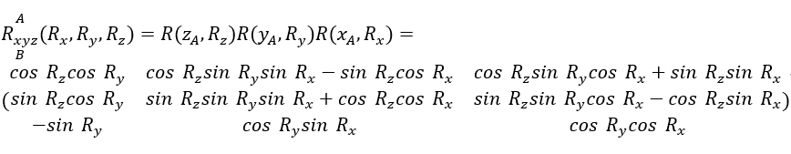
All robot spatial orientation involved in the JAKA TCP/IP control protocol adopt RPY angle representation.
In RPY, the rotation transformation sequence is rotation around the fixed coordinate system axes x-y-z in order. Rotation around the fixed coordinate system z-axis (Rz) is called Roll; rotation around the fixed coordinate system y-axis (Ry) is called Pitch; rotation around the fixed coordinate system x-axis (Rx) is called Yaw.
The robot pose data format is defined as[ X , Y , Z , Rx , Ry , Rz], where X, Y, Z represent positions on the three coordinate axes in millimeters; Rx, Ry, Rz represent the robot posture, corresponding respectively to the three RPY components Yaw, Pitch, and Roll, in degrees.
Regarding the conversion relationship with the rotation matrix, suppose we select a fixed coordinate system {A}, the RPY representation of a certain coordinate system {B} and its conversion with the rotation matrix is calculated as follows:
User Precautions
Error code description
- When the interface returns correctly, errorCode should be 0 (either int or string type) instead of Empty/Null; when errorCode is other than 0, it indicates an execution error.
- If an error occurs, the client can check errorCode and msg in the returned JSON data
- When the value returned by errorCode is 0, the message returned by errorMsg is empty, indicating successful execution;
- When the value returned by errorCode is other numbers, errorMsg will return specific error information, indicating that an exception occurred in the program.
Error Code Short Lists
Basic Robot Operations (200-249)
ERROR_INSTALLATION_ANGLE_OUT_OF_RANGE="0x000200" #installation angle out of range
Move Commands (250-349)
ERROR_SETTING_MOTION_PLANNER="0x000250"
Servo-related (350-399)
ERROR_NOT_IN_SERVO_MODE="0x000350" #try to servo when not in servo mode ERROR_SET_FILTER_IN_SERVO_MODE = "0x000351" #cannot set servo filter when in servo mode ERROR_SERVO_PARAMETER_INVALID = "0x000352" #servo params invalid ERROR_SERVO_FILTER_INVALID = "0x000353" #servo filter params invalid
IO-related (400-449)
ERROR_IO_INDEX_OUT_OF_RANGE = "0x000400" #IO index out of range ERROR_IO_TYPE_OUT_OF_RANGE = "0x000401" #IO type out of range
Program-related (450-499)
ERROR_VAR_ALIAS_EXIST = "0x000450" #var alias already exist ERROR_VAR_ID_NOT_EXIST = "0x000451" #var id not exist
Collision-related (500-549)
ERROR_COLLISION_LEVEL_OUT_OF_RANGE = "0x000500" #collision level out of range
Kinematics-related (550-599)
ERROR_FAIL_KINE_INVERSE = "0x000550" #kine_inverse fail
Torque sensor-related
Trajectory-related
Drag and force control
FTP part
TIO part
Reserved for future features
Other notes
- errorCode may be a string or an integer.
- All commands are non-blocking commands.
- The units used by the protocol are: mm (millimeters) and degree (angles).
- TCP IO index starts from 1, but SDK IO index starts from 0.
Ports 10000 and 10004 settings
Port 10004 is a dedicated SDK port, with returned data identical to port 10000.
Get the sending cycle of port 10000
Send message:
{"cmdName":"get_port10000_delay_ms"}
Receive message:
{"errorCode": "0", "errorMsg": "", "cmdName": "get_port10000_delay_ms", "port10000_delay_ms": 2000}
Modify the sending cycle of port 10000
Send message:
{"cmdName":"set_port10000_delay_ms","port10000_delay_ms":20}
Receive message:
{"errorCode": "0", "errorMsg": "", "cmdName": "set_port10000_delay_ms"}
Query the configuration of optionalInfoConfig
Send message:
{"cmdName":"getOptionalInfoConfig","section":"PORTCONFIG","key":"port10000_delay_ms"}
Receive message:
{"errorCode": "0", "errorMsg": "", "cmdName": "getOptionalInfoConfig", "value": 20}
Send message:
{"cmdName":"getOptionalInfoConfig","section":"ATTROPTIONALDATA","key":"joint_actual_position"}
Receive message:
{"errorCode": "0", "errorMsg": "", "cmdName": "getOptionalInfoConfig", "value": 1}
Modify the configuration of optionalInfoConfig
Send message:
{"cmdName":"setOptionalInfoConfig","section":"PORTCONFIG","key":"port10000_delay_ms", "value": "200"}
Receive message:
{"errorCode": "0", "errorMsg": "", "cmdName": "setOptionalInfoConfig"}
Send message:
{"cmdName":"setOptionalInfoConfig","section":"ATTROPTIONALDATA","key":"joint_actual_position", "value": 0}
Receive message:
{"errorCode": "0", "errorMsg": "", "cmdName": "setOptionalInfoConfig"}
Instruction interface introduction
The following describes the usage of each instruction by function module section, with the meaning of return fields explained under each instruction.
Basic robot operations
Turn on power
Send message:
{"cmdName":"power_on"}
Receive message:
{"errorCode": "0", "errorMsg": "", "cmdName": "power_on"}
Turn off power
Send message:
{"cmdName":"power_off"}
Receive message:
{"errorCode": "0", "errorMsg": "", "cmdName": "power_off"}
Enable robot
Send message:
{"cmdName":"enable_robot"}
Receive message:
{"errorCode": "0", "errorMsg": "", "cmdName": "enable_robot"}
Disable robot
Send message:
{"cmdName":"disable_robot"}
Receive message:
{"errorCode": "0", "errorMsg": "", "cmdName": "disable_robot"}
Shut down the robot and controller
Send message:
{"cmdName":"shutdown"}
Receive message:
null
After sending the shutdown command, the controller closes processes, the TCP server closes, and therefore no message is returned.
Robot State
Send message:
{"cmdName":"get_robot_state"}
Receive message:
{"enable": true, "power": 1, "errorMsg": "", "errcode": 0, "cmdName": "get_robot_state", "errorCode": "0", "msg": ""}
Description:
- enable: Indicates the enable status of the robot, true means enabled, false means not enabled.
- power: Indicates the power-on status of the robot, 1 means powered on, 0 means not powered on.
- errorCode: Indicates the error code corresponding to the TCP command.
- errcode: Indicates the corresponding error code returned by the controller.
- errorMsg: Indicates the error message corresponding to the TCP command.
- msg: Indicates the corresponding error message returned by the controller.
Get controller version
Send message:
{"cmdName":"get_version"}
Receive message:
{"errorMsg": "", "cmdName": "get_version", "errorCode": "0", "robot_name": "JKROBOT", "version": "1.7.1_40_rc_X64", "robot_id": "Zu20200100"}
Description:
- robot_name: Robot name
- version: Robot controller version
- robot_id: Robot serial number
Get robot installation angle
Send message:
{"cmdName":"get_installation_angle"}
Receive message:
{"installation_angle": [[x, y, z, w], [rx, ry , rz]], "errorCode": "0", "cmdName": "get_installation_angle", "errorMsg": ""}
Description:
- x, y, z, w: Installation angle represented as quaternion.
- rx, ry, rz: Installation angle represented as Euler angles.
Set robot installation angle
Send message:
{"cmdName":"set_installation_angle","angleX":angleX,"angleZ": angleZ}
Receive message:
{"errorCode": "0", "errorMsg": "", "cmdName": "set_installation_angle"}
Description:
- angleX: Robot's rotation angle in the X direction, range[ 0 to 180 ]degrees.
- angleZ: Robot's rotation angle in the Z direction, range [0, 360) degrees.
Set robot manual/automatic mode
Send message:
{"cmdName":"set_auto_manual_mode", "mode":0}
Receive message:
{"cmdName": "set_auto_manual_mode", "errorCode": "0", "errorMsg": ""}
Description:
- mode: 0 for manual mode, 1 for automatic mode
Get robot manual/automatic mode
Send message:
{"cmdName":"get_auto_manual_mode"}
Receive message:
{"mode": 1, "cmdName": "get_auto_manual_mode", "errorCode": "0", "errorMsg": ""}
Description:
- mode: 0 for manual mode, 1 for automatic mode
Set robot vibration suppression mode
Send message:
{"cmdName": "enable_vibsuppress_override","mode": 1}
Receive message:
{"cmdName": "enable_vibsuppress_override", "errorCode": "0", "errorMsg": ""}
Description:
- mode: 0: Off, 1: Mode 1, 2: Mode 2
The initial default frequency for each model is shown in the table below:
| Load/Model | Default frequency (Hz) |
|---|---|
| MiniCobot1 | 16 |
| MiniCobot2 | 15 |
| 3kg (Zu3 and similar) | 14 |
| 5kg (C5/A5/Dual-arm and similar) | 12 |
| 7kg (Zu7 and similar) | 12 |
| 12kg (Zu12 and similar) | 8 |
| 16kg(Zu16) | 7.5 |
| 18kg(Zu18) | 7.5 |
| 20kg(Zu20) | 7.5 |
| 30kg(Zu30) | 7.4 |
| Max40 | 5 |
Enable vibration suppression settings
Send message:
{"cmdName": "vib_suppress_on", "frequency": 12}
Receive message:
{"cmdName": "vib_suppress_on", "errorCode": "0", "errorMsg": ""}
Description:
- frequency: Vibration frequency
Disable vibration suppression settings
Send message:
{"cmdName": "vib_suppress_off"}
Receive message:
{"cmdName": "vib_suppress_off", "errorCode": "0", "errorMsg": ""}
Robotic arm motion related
JOG Command
The Jog command includes single-axis motion in joint space and single-axis motion in Cartesian space:
jog_mode represents the motion mode and supports 4 motion modes:
- Jog_stop (Jog stop): 0
- Continue (Continuous motion): 1
- Increment (Step motion): 2
- ABS Absolute motion: 3
coord_map represents the choice of coordinate system and supports 3 motion coordinate systems:
- Motion in world coordinate system: 0
- Motion in joint space: 1
- Motion in tool coordinate system: 2
In joint space, jnum represents the joint number; joints 1 to 6 correspond to numbers 0 to 5 respectively;
In Cartesian space, jnum represents x, y, z, rx, ry, rz. They correspond to numbers 0 to 5 respectively.
jogvel represents speed.
poscmd represents step value; single joint motion is in degrees, single-axis motion in space is in millimeters.
When jog_mode is 0, only jog_mode, coord_map, and jnum parameters are valid.
Send message:
{"cmdName":"jog","jog_mode":0, "coord_map":1, "jnum":1}
Receive message:
{"errorCode": "0", "errorMsg": "", "cmdName": "jog"}
Description:
- The sent command means stopping Jog motion of the robot's joint 2 in joint space.
When jog_mode is 1, only jog_mode, coord_map, jnum, and jogvel parameters take effect.
Send message:
{"cmdName":"jog","jog_mode":1, "coord_map":1, "jnum":1, "jogvel":30}
Receive message:
{"errorCode": "0", "errorMsg": "", "cmdName": "jog"}
Explanation:
- The sent command means that in joint space, joint 2 performs Jog motion at 30 deg/s.
- It is worth noting that the direction of motion is determined by the sign of jogvel.
- You must first stop the motion of the current axis before issuing a motion command for that axis again.
When jog_mode is 2, the parameters jog_mode, coord_map, jnum, jogvel, and poscmd are all effective.
Send message:
{"cmdName":"jog","jog_mode":2, "coord_map":1, "jnum":1, "jogvel":30, "poscmd":20}
Receive message:
{"errorCode": "0", "errorMsg": "", "cmdName": "jog"}
Explanation:
- The sent command is to control robot joint 2 to move in the positive direction at a speed of 30 deg/s for 20 deg.
- The direction of movement can be determined by the sign of poscmd.
When jog_mode is 3, the parameters jog_mode, coord_map, jnum, jogvel, and poscmd are all effective.
Send message:
{"cmdName":"jog","jog_mode":3, "coord_map":1, "jnum":1, "jogvel":30, "poscmd":20}
Receive message:
{"errorCode": "0", "errorMsg": "", "cmdName": "jog"}
Explanation:
- The sent command controls robot joint 2 to move at a speed of 30 deg/s to a target position of 20 deg.
Joint moves to the specified position MoveJ
Send message:
{"cmdName":"joint_move","relFlag":0,"jointPosition":[0,90.5,90.5,0,90.5,0],"speed":20.5,"accel":20.5}
{"cmdName":"joint_move","relFlag":0,"jointPosition":[0,90.5,90.5,0,90.5,0],"speed":20.5,"accel":20.5,"tol":0,"executing_line_id":0,"end_cond":}{"di_type":0,"di_index":0,"di_state":1}
Receive message:
{"errorCode": "0", "errorMsg": "", "cmdName": "joint_move"}
Description:
- relFlag: Optional values are 0 or 1, where 0 means absolute movement and 1 means relative movement.
- jointPosition: [j1,j2,j3,j4,j5,j6] are the angle values for each joint. The unit is degrees, not radians. The direction of movement is determined by the sign of the jointPosition value.
- speed: Represents the joint speed, unit is (°/S), and the user can fill in appropriate values.
- accel: Represents the joint acceleration, unit is (°/S²), and the user can fill in appropriate values. It is recommended that the acceleration value not exceed 720.
- joint_move is a blocking (inside the controller, does not affect immediate return of commands) motion instruction, where one motion instruction must finish before the next is executed. If the next command needs to be executed immediately, it is recommended to first use stop_program to stop the current motion before sending the next motion instruction.
- tol (optional parameter): Transition radius parameter between motion paths, default value is 0.
- executing_line_id (optional parameter): The ID number of this motion instruction, default value is 0.
- end_cond (optional parameter): Condition for skipping the motion instruction; if the IO in the condition is met, the instruction will be skipped and not executed.
- di_type: IO type.
- di_index: IO number.
- di_state: Target value of the IO.
TCP endpoint moves to the specified position.
Send message:
{"cmdName":"end_move","endPosition":[100,200.1,200.5,0,0,0], "speed":21.5, "accel":31.5}
{"cmdName":"end_move","endPosition":[100,200.1,200.5,0,0,0], "speed":21.5, "accel":31.5,"tol":0,"executing_line_id":0,"end_cond":}{"di_type":0,"di_index":0,"di_state":1}
Receive message:
{"errorCode": "0", "errorMsg": "", "cmdName": "end_move"}
Description:
- endPosition: [x,y,z,a,b,c] specifies the values of xyzabc for the TCP endpoint.
- speed: speed_val represents joint speed, unit is (°/S), and the user can fill in appropriate values. If speed_val is set to 20, it means the joint speed is 20 °/S.
- accel: accel_val represents joint acceleration, unit is (°/S²), and the user can fill in appropriate values. It is recommended that the acceleration value not exceed 720.
- end_move is a blocking motion command. The next motion command will only be executed after the current one finishes. If the next command needs to be executed immediately, it is recommended to first use stop_program to stop the current motion before sending the next motion instruction.
- The end_move command does not move in a straight line from the current position to the target point. Instead, it first performs inverse kinematics on the user’s input Cartesian space target point, and then uses the joint_move command to move the robot joints to the specified position.
- If you need to move in a straight line from the current position to the target point, you need to use the moveL command.
- tol (optional parameter): Transition radius parameter between motion paths, default value is 0.
- executing_line_id (optional parameter): The ID number of this motion instruction, default value is 0.
- end_cond (optional parameter): Condition for skipping the motion instruction; if the IO in the condition is met, the instruction will be skipped and not executed.
- di_type: IO type.
- di_index: IO number.
- di_state: Target value of the IO.
Linear Motion MoveL
Send message:
{"cmdName":"moveL","relFlag":1,"cartPosition":[0,0,50,0,0,0],"speed":20,"accel":50,"tol":0.5}
{"cmdName":"moveL","relFlag":1,"cartPosition":[0,0,50,0,0,0],"speed":20,"accel":50,"tol":0.5,"tol":0,"executing_line_id":0,"end_cond":{"di_type":0,"di_index":0,"di_state":1},"ori_vel":180,"ori_acc":720}
Receive message:
{"errorCode": "0", "errorMsg": "", "cmdName": "moveL"}
Description:
- cartPosition: [x,y,z,rx,ry,rz] Specifies the values of x, y, z, rx, ry, rz in Cartesian space.
- speed: speed_val represents the linear velocity, in (mm/s). Users can enter parameters that are appropriate. If speed_val is set to 20, it means the linear velocity is 20 mm/s.
- accel: accel_val represents the acceleration for linear motion, in (mm/S²). Users can enter parameters that are appropriate. It is recommended that the acceleration value not exceed 8000.
- relFlag: flag_val can be either 0 or 1. 0 represents absolute motion, 1 represents relative motion.
- moveL is a blocking motion command. The next motion command will only be executed after the current one finishes. If the next command needs to be executed immediately, it is recommended to first use stop_program to stop the current motion before sending the next motion instruction.
- tol (optional parameter): Transition radius parameter between motion paths, default value is 0.
- executing_line_id (optional parameter): The ID number of this motion instruction, default value is 0.
- end_cond (optional parameter): Condition for skipping the motion instruction; if the IO in the condition is met, the instruction will be skipped and not executed.
- di_type: IO type.
- di_index: IO number.
- di_state: Target value of the IO.
- ori_vel (optional parameter): TCP rotation speed when changing orientation, default value is 180°/s
- ori_acc (optional parameter): TCP rotational acceleration when changing orientation, default value is 720°/S²
Arc Motion MoveC
Send message:
{"cmdName":"movc","relFlag":move_mode,"pos_mid":[x,y,z,rx,ry,rz],"pos_end":[x,y,z,rx,ry,rz],"speed":vel,"accel":acc,"tol":tol,"executing_line_id":0,"end_cond":{"di_type":0,"di_index":0,"di_state":1},"circle_mode":0,"circle_cnt":0}
Receive message:
{"errorCode": "0", "errorMsg": "", "cmdName": "movc"}
Description:
- pos_mid: [x,y,z,rx,ry,rz] Specifies the values of x, y, z, rx, ry, rz in Cartesian space.
- pos_end: [x,y,z,rx,ry,rz] Specifies the values of x, y, z, rx, ry, rz in Cartesian space.
- speed: speed_val represents the joint speed, in (°/S). Users can enter parameters that are appropriate. If speed_val is set to 20, it means the joint speed is 20 °/S.
- accel: accel_val represents joint acceleration, unit is (°/S²), and the user can fill in appropriate values. It is recommended that the acceleration value not exceed 720.
- tol (optional parameter): Transition radius parameter between motion paths, default value is 0.
- executing_line_id (optional parameter): The ID number of this motion instruction, default value is 0.
- end_cond (optional parameter): Condition for skipping the motion instruction; if the IO in the condition is met, the instruction will be skipped and not executed.
- di_type: IO type.
- di_index: IO number.
- di_state: Target value of the IO.
- circle_mode (optional parameter): Arc motion mode, default value is 0. For specific usage, refer to the APP manual.
- circle_cnt (optional parameter): Number of arc motion loops, default value is 0. For specific usage, refer to the APP manual.
Query Motion Status
Send message:
{"cmdName":"get_motion_state"}
Receive message:
{"queue": 0, "errorMsg": "", "cmdName": "get_motion_state", "queue_full": false, "active_queue": 0, "inpos": true, "paused": false, "err_add_line": 0, "errorCode": "0", "motion_line": 0}
Description:
- queue_full: Determines whether the queue is full. false means not full; true means full.
- queue: Number of motion commands in the queue.
- inpos: Position reached status flag. false means not reached (still moving), true means reached (generally in a stopped state).
- paused: Motion pause status flag. false means not paused, true means paused.
- err_add_line: The line number of the motion command when it is ignored due to repetition on the same controller.
- motion_line: Motion command ID
Get robot DH parameters
Send message:
{"cmdName":"get_dh_param"}
Receive message:
{"errorCode": "0", "errorMsg": "", "dh_param": [[0.0, 90.0, 0.0, 0.0, 90.0, -90.0], [0.0, 0.0, 897.0, 744.5, 0.0, 0.0], [196.5, 0.0, 0.0, -188.35000610351562, 138.5, 120.5], [0.0, 0.0, 0.0, 0.0, 0.0, 0.0]], "cmdName": "get_dh_param"}
Description:
- dh_param: In the returned list, each element represents in order by index: alpha, a, d, joint_homeoff.
- alpha: Link twist angle
- a: Link length
- d: Link offset
- joint_homeoff: Joint zero-point offset
Get user coordinate system information
Send message:
{"cmdName":"get_user_offsets"}
Receive message:
{"user_offsets": [[0.0, 0.0, 0.0, 0.0, 0.0, 0.0], [0.0, 0.0, 0.0, 0.0, 0.0, 0.0], [0.0, 0.0, 0.0, 0.0, 0.0, 0.0], [0.0, 0.0, 0.0, 0.0, 0.0, 0.0], [0.0, 0.0, 0.0, 0.0, 0.0, 0.0], [0.0, 0.0, 0.0, 0.0, 0.0, 0.0], [0.0, 0.0, 0.0, 0.0, 0.0, 0.0], [0.0, 0.0, 0.0, 0.0, 0.0, 0.0], [0.0, 0.0, 0.0, 0.0, 0.0, 0.0], [0.0, 0.0, 0.0, 0.0, 0.0, 0.0], [0.0, 0.0, 0.0, 0.0, 0.0, 0.0], [0.0, 0.0, 0.0, 0.0, 0.0, 0.0], [0.0, 0.0, 0.0, 0.0, 0.0, 0.0], [0.0, 0.0, 0.0, 0.0, 0.0, 0.0], [0.0, 0.0, 0.0, 0.0, 0.0, 0.0], [0.0, 0.0, 0.0, 0.0, 0.0, 0.0], [0.0, 0.0, 0.0, 0.0, 0.0, 0.0], [0.0, 0.0, 0.0, 0.0, 0.0, 0.0], [0.0, 0.0, 0.0, 0.0, 0.0, 0.0], [0.0, 0.0, 0.0, 0.0, 0.0, 0.0], [0.0, 0.0, 0.0, 0.0, 0.0, 0.0], [0.0, 0.0, 0.0, 0.0, 0.0, 0.0], [0.0, 0.0, 0.0, 0.0, 0.0, 0.0]], "cmdName": "get_user_offsets", "errorCode": "0", "errorMsg": ""}
Description:
- tool_offset: There are 23 sets of data (0~23), including world coordinate system + user-defined coordinate system (15) + robot factory installation coordinate system (7) (dual-arm built-in).
Set Sensor Coordinates
Send message:
{"cmdName":"set_user_offsets","userffset":[10,10,10,10,10,10],"id":2,"name":"user_new"}
Receive message:
{"errorCode": "0", "errorMsg": "", "cmdName": "set_user_offsets"}
Description:
- userffset: Fill in the x, y, z, rx, ry, rz of the user coordinate system, such as [10,10,10,10,10,10] in the example.
- id: The ID number of the user coordinate system you want to set, selectable IDs are 1 to 15. Example: Set user coordinate system 2.
- name: The name of the user coordinate system you want to set. For example, set the name to user_new.
- This command only sets the coordinate system values, but does not actually select this coordinate system.
Get current user coordinate system information
Send message:
{"cmdName":"get_curr_user_offset"}
Receive message:
{"errorCode": "0", "errorMsg": "", "cmdName": "get_curr_user_offset", "user_offset": [-590.0, 380.0, -1230.0, 0.0, 0.0, 0.0]}
Select user coordinate system
Send message:
{"cmdName":"set_user_id","user_frame_id":2}
Receive message:
{"errorCode": "0", "errorMsg": "", "cmdName": "set_user_id"}
Description:
- set_user_id: User coordinate system ID number. Used to choose which user coordinate system to move under. For example, setting the ID to 2 means moving under the second user coordinate system.
- It should be noted that when set_user_id is set to 0, it means the robot moves under the base coordinate system (world coordinate system).
Get current user coordinate system
Send message:
{"cmdName":"get_curr_user_id"}
Receive message:
{"errorCode": "0", "errorMsg": "", "id": 10, "cmdName": "get_curr_user_id"}
Select tool coordinate system
Send message:
{"cmdName":"set_tool_id","tool_id":2}
Receive message:
{"errorCode": "0", "errorMsg": "", "cmdName": "set_tool_id"}
Description:
- tool_id: Tool coordinate system ID number. Used to choose which tool coordinate system to move under. For example, setting the ID to 2 means moving under the second tool coordinate system.
- It should be noted that when tool_id is 0, the robot's tool defaults to the center of the end flange.
Get the current tool coordinate system
Send message:
{"cmdName":"get_curr_tool_id"}
Receive message:
{"errorCode": "0", "errorMsg": "", "id": 2, "cmdName": "get_curr_tool_id"}
Set Sensor Coordinates
Send message:
{"cmdName":"set_tool_offsets","tooloffset":[10,10,10,10,10,10],"id":2,"name":"tcp_new"}
Receive message:
{"errorCode": "0", "errorMsg": "", "cmdName": "set_tool_offsets"}
Description:
- tooloffset: Fill in the x, y, z, rx, ry, rz of the tool coordinate system. For example, [10,10,10,10,10,10 in the example].
- id: The ID number of the tool coordinate system you want to set, optional IDs are from 1 to 15. For example, set tool coordinate system 2.
- name: The name of the tool coordinate system you want to set. For example, set the name to tcp_new.
Get tool coordinate system information
Send message:
{"cmdName":"get_tool_offsets"}
Receive message:
{"errorCode": "0", "errorMsg": "", "tool_offsets": [[0.0, 0.0, 0.0, 0.0, 0.0, 0.0], [0.0, 0.0, 0.0, 0.0, 0.0, 0.0], [0.0, 0.0, 0.0, 0.0, 0.0, 0.0], [0.0, 0.0, 0.0, 0.0, 0.0, 0.0], [0.0, 0.0, 0.0, 0.0, 0.0, 0.0], [0.0, 0.0, 0.0, 0.0, 0.0, 0.0], [0.0, 0.0, 0.0, 0.0, 0.0, 0.0], [0.0, 0.0, 0.0, 0.0, 0.0, 0.0], [0.0, 0.0, 0.0, 0.0, 0.0, 0.0], [0.0, 0.0, 0.0, 0.0, 0.0, 0.0], [0.0, 0.0, 0.0, 0.0, 0.0, 0.0], [0.0, 0.0, 0.0, 0.0, 0.0, 0.0], [0.0, 0.0, 0.0, 0.0, 0.0, 0.0], [0.0, 0.0, 0.0, 0.0, 0.0, 0.0], [0.0, 0.0, 0.0, 0.0, 0.0, 0.0], [0.0, 0.0, 0.0, 0.0, 0.0, 0.0]], "cmdName": "get_tool_offsets"}
Description:
- tool_offset: There are 16 sets of data (0~15), corresponding to the tool coordinate system offset of the relative ID, 0 represents the default end flange center coordinate system.
Get current coordinate system information
Send message:
{"cmdName":"get_curr_tool_offset"}
Receive message:
{"errorCode": "0", "errorMsg": "", "cmdName": "get_curr_tool_offset", "tool_offset": [0.0, 0.0, 130.0, 0.0, 0.0, -90.0]}
Set load
Send message:
{"cmdName":"set_payload","mass":m,"centroid":[x,y,z]}
Receive message:
{"errorCode": "0", "errorMsg": "", "cmdName": "set_payload"}
Description:
- mass is the weight of the load, in kilograms (KG). centroid is the center of mass of the load, in millimeters. For example, set the load weight to 1KG and the center of mass to [10,10,10]. Then you can send the command:
{"cmdName":"set_payload","mass":1,"centroid":[10,10,10]}
Get load
Send message:
{"cmdName":"get_payload"}
Receive message:
{"errorCode": "0", "centroid": [0.0, 0.0, 1.0], "mass": 1.0, "cmdName": "get_payload", "errorMsg": ""}
Description:
- mass: The weight of the load, in kilograms (KG).
- centroid: The center of mass of the load, in millimeters.
Get joint positions
Send message:
{"cmdName":"get_joint_pos"}
Receive message:
{"errorCode": "0", "errorMsg": "", "cmdName": "get_joint_pos", "joint_pos": [j1,j2,j3,j4,j5,j6]}
Description:
- j1,j2,j3,j4,j5,j6 are the positions of the six returned joints, in degrees.
Get current actual joint positions
Send message:
{"cmdName":"get_actual_joint_pos"}
Receive message:
{"errorCode": "0", "position": [285.8061097309843, 80.09823788479945, 60.72657603991451, 124.99045041547085, -85.27718451168131, 316.9348226974971], "cmdName": "get_actual_joint_pos", "errorMsg": ""}
Description:
- position: Returns a six-dimensional list representing each joint angle.
Get end pose under the current coordinate system
Send message:
{"cmdName":"get_tcp_pos"}
Receive message:
{"errorCode": "0", "errorMsg": "", "cmdName": " get_tcp_pos", "tcp_pos": [x,y,z,a,b,c]}
Description:
- [x,y,z,a,b,c] are the end pose under the current set tool coordinate system, by default the tool coordinate system is the center of the flange.
Get the current actual Cartesian pose
Send message:
{"cmdName":"get_actual_tcp_pos"}
Receive message:
{"errorCode": "0", "position": [604.2014815031182, -71.01229318144345, 1669.033510162098, -179.4141090762053, -6.279762125819193, 149.01179247501761], "cmdName": "get_actual_tcp_pos", "errorMsg": ""}
Description:
- Return a six-dimensional list representing each Cartesian pose.
Set the robot speed multiplier
Send message:
{"cmdName":"rapid_rate","rate_value":0.2}
Receive message:
{"errorCode": "0", "errorMsg": "", "cmdName": "rapid_rate"}
Description:
- rate_value: By default, the robot's program runs at a multiplier of 1. This command allows you to modify it, with a range from 0 to 1.
Get the current rate
Send message:
{"cmdName":"get_rapid_rate"}
Receive message:
{"errorCode": "0", "errorMsg": "", "cmdName": "get_rapid_rate", "value": 1.0}
Description:
- value: Current rate, range [0,1]
Check if it is in soft limit
Send message:
{"cmdName":"is_on_limit"}
Receive message:
{"errorCode": "0", "errorMsg": "", "on_limit": 0, "cmdName": "is_on_limit"}
Description:
- on_limit: True means the robot is currently in soft limit, False means it is not.
Check emergency stop status
Send message:
{"cmdName":"emergency_stop_status"}
Receive message:
{"errorCode": "0", "errorMsg": "", "emergency_stop": 0, "cmdName": "emergency_stop_status"}
Description:
- emergency_stop: Indicates whether it is in emergency stop status. 0 means not in emergency stop; 1 means in emergency stop.
Set motion planner
Send message:
{"cmdName":"set_motion_planner","type":1}
Receive message:
{"errorCode": "0", "errorMsg": "", "cmdName": "set_motion_planner"}
Description:
- type: Motion planner type, selectable values are -1, 0, 1. -1 means disable the planner, 0 means choose T planning, 1 means choose S planning.
Servo related
Check if servo position control mode is entered
Send message:
{"cmdName":"is_in_servomove"}
Receive message:
{"errorCode": "0", "errorMsg": "", "in_servomove": true, "cmdName": "is_in_servomove"}
Description:
- in_servomove: true, in servo mode. false, not in servo mode.
Enable robot servo position control
Send message:
{"cmdName":"servo_move","relFlag":0}
{"cmdName":"servo_move","relFlag":1,"is_block":0}
Receive message:
{"errorCode": "0", "errorMsg": "", "cmdName": "servo_move"}
Description:
- relFlag: 1 means enter servo_move mode, 0 means exit.
- is_block: 0 means non-blocking mode, 1 means blocking mode.
Joint space position control mode
Send message:
{"cmdName":"servo_j","relFlag":1,"jointPosition":[0.1,0,0,0,0,0],"stepNum":1}
Receive message:
{"errorCode": "0", "errorMsg": "", "cmdName": "servo_j"}
Description:
- The user can generate the angles for six joints and send them to the robot to control it to reach the corresponding target position.
- Before using the servo_j command, the user needs to use the servo_move command to enter servo position control mode.
- jointPosition: [joint1, joint2, joint3, joint4, joint5, joint6] — fill in the angles of each joint, in degrees.
- relFlag: relFlag optional parameters are 0 and 1. 0 represents absolute motion, 1 represents relative motion.
- stepnum: This is a cycle frequency division, and the robot will execute the received servo motion command at a cycle of num*8ms.
- It should be noted that since the controller's control cycle is 8ms, this command needs to be sent every 8ms to be effective, and must be sent continuously. Sending it only once will not show any effect, and the maximum speed of the six joints is 180 degrees/second. For example[, 1.5,0.5,0.5,0.5,0.5,0.5], 1.5/0.008=187.5 exceeds the joint speed limit, so the servo_j command will not take effect.
Attention:
The difference between this command and joint_move is quite significant. This command is mainly used in scientific research for trajectory planning. When this command is sent to the robot, it does not go through the controller’s planner for interpolation, but is sent directly to the servo. When using this command, the user needs to plan the trajectory in advance; otherwise, the result will be poor and will not meet expectations. In general, it is recommended to use the joint_move command.
Cartesian space position control mode
relFlag: 0 means absolute motion, 1 means relative motion
Send message:
{"cmdName":"servo_p","catPosition":[x,y,z,a,b,c],"relFlag":0,"stepNum":1}
Receive message:
{"errorCode": "0", "errorMsg": "", "cmdName": "servo_p"}
Description:
- Users can use their own trajectory planning algorithms to generate point coordinates for each joint, and then send them to the robot's six joints, and the robot can execute these commands.
- Before using the servo_p command, the user needs to first use the servo_move command to enter the servo position control mode.
- catPosition: [x,y,z,a,b,c] means that in Cartesian space, the coordinates xyz are in millimeters, and abc are in degrees.
- abc represents the Euler angle sequence of the robot's posture as XYZ.
- relFlag: 0 Optional values for relFlag are 0 and 1. 0 represents absolute motion, 1 represents relative motion.
- stepnum: This is a cycle frequency division, and the robot will execute the received servo motion command at a cycle of num*8ms.
- It should be noted that this command needs to be sent every 8ms to be effective. Because the controller interpolates a position point every 8ms. Also, the values of x, y, z, a, b, c should not be too large to avoid exceeding the controller's safe speed limit.
Attention:
This command is mainly used in scientific research for trajectory planning, and when using this command, the controller’s planner does not perform interpolation. When using this command, the user needs to plan the trajectory in advance; otherwise, the result will be poor and will not meet expectations. In general, it is recommended to use moveL.
Servo mode filter
- The set_servo_move_filter command sets the servo mode filter to assist in trajectory planning.
- filter_type represents motion modes, with 6 possible values:
- no_filter disables the filter: 0
- Joint space first-order low-pass filter: 1
- Joint space nonlinear filter: 2
- Joint space multi-order mean filter: 3
- Cartesian space nonlinear filter: 4
- Velocity preview: 5
When filter_type is 0, there is only 1 parameter
Send message:
{"cmdName":"set_servo_move_filter","filter_type":0}
Receive message:
{"errorCode": "0", "errorMsg": "", "cmdName": "set_servo_move_filter"}
Description:
Disable the filter, do not use the filter for auxiliary planning, must be set after exiting servo mode.
When filter_type is 1, there are only 2 parameters
Send message:
{"cmdName":"set_servo_move_filter","filter_type":1",lpf_cf":0.5}
Receive message:
{"errorCode": "0", "errorMsg": "", "cmdName": "set_servo_move_filter"}
Description:
(a) Set the joint space first-order low-pass filter, must be set after exiting servo mode.
(b) lpf_cf indicates the cutoff frequency, in HZ.
When filter_type is 2, there are only 4 parameters
Send message:
{"cmdName":"set_servo_move_filter","filter_type":2,"nlf_max_vr":2,"nlf_max_ar":2,"nlf_max_jr":4}
Receive message:
{"errorCode": "0", "errorMsg": "", "cmdName": "set_servo_move_filter"}
Description:
(a) Set the joint space nonlinear filter, must be set after exiting servo mode.
(b) max_vr Maximum limit value (absolute value) for attitude change speed °/s.
(c) max_ar Maximum limit value (absolute value) for acceleration of attitude change speed °/s^2.
(d) max_jr Maximum limit value (absolute value) for jerk of attitude change speed °/s^3.
When filter_type is 3, there are only 5 parameters
Send message:
{"cmdName":"set_servo_move_filter","filter_type":3,"mmf_max_buf":20,"mmf_kp":0.1,"mmf_kv":0.2,"mmf_ka":0.6}
Receive message:
{"errorCode": "0", "errorMsg": "", "cmdName": "set_servo_move_filter"}
Description:
(a) Set the joint space multi-order mean filter, must be set after exiting servo mode.
(b) mmf_max_buf: Filter window width. The larger it is, the smoother the filtered trajectory, but accuracy will be lost.
(c) mmf_kp: Position tracking coefficient. The smaller it is, the smoother the filtered trajectory; the larger it is, the higher the accuracy, but there may be jitter.
(d) mmf_kv: Velocity tracking coefficient. The smaller it is, the smoother the filtered trajectory; the larger it is, the higher the accuracy, but there may be jitter.
(e) mmf_ka: The smaller the acceleration position tracking coefficient, the smoother the filtered trajectory; the larger it is, the higher the accuracy, but there may be jitter.
When filter_type is 4, there are only 7 parameters.
Send message:
{"cmdName":"set_servo_move_filter","filter_type":4,"nlf_max_vr":2,"nlf_max_ar":2,"nlf_max_jr":4,"nlf_max_vp":10,"nlf_max_ap":100,"nlf_max_jp":200}
Receive message:
{"errorCode": "0", "errorMsg": "", "cmdName": "set_servo_move_filter"}
Description:
(a) Set the Cartesian space nonlinear filter; this must be set after exiting servo mode.
(b) max_vr Maximum limit value (absolute value) of the speed of orientation change in Cartesian space, in °/s.
(c) max_ar Maximum limit value (absolute value) of the acceleration of orientation change speed in Cartesian space, in °/s^2.
(d) max_jr Maximum limit value (absolute value) of the jerk of orientation change speed in Cartesian space, in °/s^3.
(e) max_vp Maximum limit value (absolute value) of the speed of movement commands in Cartesian space. Unit: mm/s.
(f) max_ap Maximum limit value (absolute value) of the acceleration of movement commands in Cartesian space. Unit: mm/s^2.
(g) max_jp Maximum limit value (absolute value) of the jerk of movement commands in Cartesian space. Unit: mm/s^3.
When filter_type is 5, there are only 3 parameters.
Send message:
{"cmdName":"set_servo_move_filter","filter_type":5,"mmf_max_buf":max_buf,"mmf_kp":kp}
Receive message:
{"errorCode": "0", "errorMsg": "", "cmdName": "set_servo_move_filter"}
Description:
(a) Set the joint space multi-order mean filter, must be set after exiting servo mode.
(b) max_buf Size of the moving average filter buffer.
(c) mmf_kp Acceleration filtering coefficient.
Set the drag mode switch.
Send message:
{"cmdName":"torque_control_enable","enable_flag":0}
Receive message:
{"errorCode": "0", "errorMsg": "", "cmdName": "torque_control_enable"}
Description:
- enable_flag, 0 turns off drag mode, 1 turns on drag mode.
Get drag status.
Send message:
{"cmdName":"get_drag_status"}
Receive message:
{"status": false, "errorCode": "0", "cmdName": "get_drag_status", "errorMsg": ""}
Description:
- drag_status: True means the robot is currently in drag mode and the user can perform drag programming; False means the opposite.
Set drag compensation coefficient.
Send message:
{"cmdName":"robot_set_drag_parameters", "mode":1, "friction_compensation_ratio":[50, 50, 50, 50, 50, 50]}
Receive message:
{"errorCode": "0", "cmdName": "robot_set_drag_parameters"}
Description:
- mode: Drag mode.
- friction_compensation_ratio: Friction compensation coefficient, 6 parameters, each ranging from 0 to 150, in percentage.
Get drag compensation coefficient.
Send message:
{"cmdName":"robot_get_drag_parameters"}
Receive message:
{"advanced_mode_supported": 1, "mode": 0, "friction_compensation_ratio_servo": [50.0, 50.0, 50.0, 50.0, 50.0, 50.0, 0.0], "friction_compensation_ratio_controller": [0.333, 0.333, 0.333, 0.333, 0.333, 0.333, 0.333], "errorCode": "0", "cmdName": "robot_get_drag_parameters"}
Description:
- advanced_mode_supported: Whether drag mode supports advanced mode
- mode: Drag mode.
- friction_compensation_ratio_servo: Friction compensation coefficient in servo drag mode, 6 parameters, each parameter ranges from 0-150, unit is percentage.
- friction_compensation_ratio_controller: Friction compensation coefficient in controller drag mode, 6 parameters, each parameter ranges from 0-1.
IO settings related
Set the value of a digital output variable (DO)
Send message:
{"cmdName":"set_digital_output","type":0,"index":1,"value":1}
{"cmdName":"set_digital_output","type":2,"index":1,"value":1,"submod":44869}
Receive message:
{"errorCode": "0", "errorMsg": "", "cmdName": "set_digital_output"}
Description:
- type is the DO type: 0--Controller IO; 1--Tool IO; 2--Extended IO; 3--Reserved; 4--modbusIO; 5--Profinet IO; 6--Ethernet/IP IO.
- index is the DO number. If you want to control the first DO, set index to 1, meaning the index starts from 1.
- value is the DO value, optional values are 0 or 1.
- submod is the submodule number of the Extended IO (optional parameter).
Get the value of a digital output variable (DO)
Send message:
{"cmdName":"get_digital_output","type":0,"index":1}
{"cmdName":"get_digital_output","type":2,"index":1,"submod":44869}
Receive message:
{"errorCode": "0", "errorMsg": "", "cmdName": "get_digital_output", "value": 0}
Description:
- type is the DO type: 0--Controller AO; 1--Tool IO; 2--Extended AO; 3--Reserved; 4--modbusIO; 5--Profinet IO; 6--Ethernet/IP IO.
- index is the DO number. For example, if the DO number to control is 1~31 and you want to control the 31st DO, set index to 31, meaning the index starts from 1.
- value is the DO value, optional values are 0 or 1.
- submod is the submodule number of the Extended IO (optional parameter).
Get the status of a specified digital input
Send message:
{"cmdName":"get_digital_input","type":0,"index":1}
{"cmdName":"get_digital_input","type":0,"index":1,"submod":44869}
Receive message:
{"errorCode": "0", "errorMsg": "", "cmdName": "get_digital_input", "value": 0}
Description:
- type is the DO type: 0--Controller AO; 1--Tool IO; 2--Extended AO; 3--Reserved; 4--modbusIO; 5--Profinet IO; 6--Ethernet/IP IO.
- index is the DO number. For example, if the DO number to control is 1~31 and you want to control the 31st DO, set index to 31, meaning the index starts from 1.
- value is the DO value, optional values are 0 or 1.
- submod is the submodule number of the Extended IO (optional parameter).
Get the status of all digital inputs
Send message:
{"cmdName":"get_digital_input_status"}
{"cmdName":"get_digital_input_status", "type":0}
{"cmdName":"get_digital_input_status", "type":2, "submod": 44869}
Receive message:
{"din_status": [0, 0, 0, 0, 0, 0, 0, 0, 0, 0, 0, 0, 0, 0, 0, 0], "cmdName": "get_digital_input_status", "errorCode": "0", "errorMsg": ""}
Description:
- type is the DI type: 0--Controller AO; 1--Tool IO; 2--Extended AO; 3--Reserved; 4--modbusIO; 5--Profinet IO; 6--Ethernet/IP IO.
- submod is the submodule number of the Extended IO (optional parameter).
Set the value of an analog output variable (AO)
Send message:
{"cmdName":"set_analog_output","type":3,"index":1,"value":0}
{"cmdName":"set_analog_output","type":2,"index":1,"value":0,"submod": 44869}
Receive message:
{"errorCode": "0", "errorMsg": "", "cmdName": "set_analog_output"}
Description:
- type is the AO type: 0--Controller AO; 1--Tool IO; 2--Extended AO; 3--Reserved; 4--modbusIO; 5--Profinet IO; 6--Ethernet/IP IO.
- index is the AO number. For example, if the AO number to control is 0~7 and you want to control the 7th AO, set index to 7.
- value is the AO value. You can input a floating-point number to meet programming requirements.
- submod is the submodule number of the Extended IO (optional parameter).
Get the value of an analog output variable (AO)
Send message:
{"cmdName":"get_analog_output","type":0,"index":1}
{"cmdName":"get_analog_output","type":2,"index":1,"submod": 44869}
Receive message:
{"errorCode": "0", "errorMsg": "", "cmdName": "get_analog_output", "value": 0.0}
Description:
- type is the AO type: 0--Controller AO; 1--Tool IO; 2--Extended AO; 3--Reserved; 4--modbusIO; 5--Profinet IO; 6--Ethernet/IP IO.
- index is the AO number. For example, if the AO number to control is 0~7 and you want to control the 7th AO, set index to 7.
- value is the AO value. You can input a floating-point number to meet programming requirements, such as 4.32.
- submod is the submodule number of the Extended IO (optional parameter).
Get the status of the Extended IO
Send message:
{"cmdName":"get_extio_status"}
Receive message:
- When there is no extension module:
{"errorCode": "0", "errorMsg": "", "cmdName": "get_extio_status", "extio_status":} {"status": "[[], [], [], []]", "setup": "[]", "num": 0, "pinmap": "[]", "mode": 0}
- When there is an extension module:
{"extio_status": {"num": 1, "mode": [[23014, 0, 0]], "setup": "[[1, \"test\", [1, \"192.168.220.144\", 2486], [[], [], [], []], \"ext_kt7dnnl0f7m75b4b\", 23014, 1000.0, 3, 1000, 1]]", "status": "[[23014, 0, 0, [], [], [], []]]"}, "cmdName": "get_extio_status", "errorCode": "0", "errorMsg": ""}
Description of extio_status:
- num: Indicates there are num external expansion IO modules.
- mode: In order, submodule number, status, error code
- setup: [[type, name, (comm), (di_startRegAddr, di_pinNum), (do_startRegAddr, do_pinNum), (ai_startRegAddr, ai_pinNum), (ao_startRegAddr, ao_pinNum)], ...]
- [[1, 8],[ 17, 8],[ 0, 0],[ 0, 0]] The four lists represent: digital input, digital output, analog input, analog output. The first number in parentheses indicates the starting allocation address of the external expansion module register. The second number indicates the quantity of IOs.
- status: [[submod, status, errcode,[ dival, ...], [doval, ...], [[aivtype, aival], ...], [[aovtype, aoval], ...], ...]]
Get the status of function input pins
Send message:
{"cmdName":"get_funcdi_status"}
Receive message:
{"errorCode": "0", "errorMsg": "", "funcdi_status": [[-1, -1], [-1, -1], [-1, -1], [-1, -1], [-1, -1], [-1, -1], [-1, -1], [-1, -1], [0,2], [-1,- 1], [-1, -1], [-1, -1]], "cmdName": "get_funcdi_status"}
Description:
- funci_status: Returns a total of 12 function input pins, which are:
- 1 Start program,
- 2 Pause program,
- 3 Resume program,
- 4 Stop program,
- 5 Turn on power,
- 6 Turn off power,
- 7 Enable robot,
- 8 Disable robot,
- 9 Level 1 reduced mode,
- 10 Protective stop,
- 11 Return to initial position,
- 12 Level 2 reduced mode.
- 13 Error clear
- 14 Drag mode
- 15 Disable drag mode
- [type, index, module]: [-1, -1, -1 ]are the default values indicating no input pins are set as function pins.
The value of Type has three options:
- 0 represents the control cabinet input pin,
- 1 represents the robot end tool input pin,
- 2 represents the Modbus input pin.
Index represents the index number of the input pin, indicating which pin is set as a function pin. As mentioned above, [0,2 ]indicates that the third pin of the control cabinet (index number starts from 0) is set as the primary reduction mode function pin.
Module represents the submodule number of the input pin (extended IO)
TIO related
Set TIO V3 tool voltage
Send message:
{"cmdName":"set_tio_vout_param","tio_vout_ena":0,"tio_vout_vol":0}
Receive message:
{"errorCode": "0", "errorMsg": "", "cmdName": "set_tio_vout_param"}
Description:
The tio_vout_ena parameter is 0 or 1. 0 means disable, 1 means enable.
The tio_vout_vol parameter is 0 or 1. 0 means 24V, 1 means 12V.
Get TIO V3 tool voltage
Send message:
{"cmdName":"get_tio_vout_param"}
Receive message:
{"errorCode": "0", "errorMsg": "", "tio_vout_ena": 0, "tio_vout_vol": 0, "cmdName": "get_tio_vout_param"}
Description:
The tio_vout_ena parameter is 0 or 1. 0 means not enabled, 1 means enabled.
The tio_vout_vol parameter is 0 or 1. 0 means 24V, 1 means 12V.
Add or modify signal
Send message:
{"cmdName":"add_tio_rs_signal","tio_signal_name":<>,"tio_signal_chnId":<>,"tio_signal_sigType":<>,"tio_signal_sigAddr":<>,"frequency":<>}
Receive message: {"errorCode": "0", "errorMsg": "", "cmdName": "add_tio_rs_signal"} Explanation:
- tio_signal_name: Identifier name (limited to 20 characters or fewer)
- tio_signal_chnId: RS485 channel ID
- tio_signal_sigType: Signal type
- tio_signal_sigAddr: Register address
- frequency: The signal refresh rate inside the controller must be no greater than 10
Get RS485 signal list
Send message:
{"cmdName":"get_rs485_signal_list"}
Receive message: Return when there is no semaphore:
{"errorCode": "0", "errorMsg": "", "num": 0, "cmdName": "get_rs485_signal_list"}
Return when there is a semaphore:
{"errorCode": "0", "errorMsg": "", "cmdName": "get_rs485_signal_list", "num":<>,} {"signalName":{"sigType": <>, "sigAddr": <>, "chnId": <>, "frequency": <>, "value": <>}
num is the number of semaphores; the order of key-value pairs is not fixed. For example:
{"c": {"sigType": 3, "sigAddr": 512, "chnId": 1, "frequency": 4.0, "value": 0}, "b": {"sigType": 3, "sigAddr": 514, "chnId": 1, "frequency": 5.0, "value": 1000}, "errorMsg": "", "cmdName": "get_rs485_signal_list", "errorCode": "0", "num": 2}
Explanation:
- num, indicates the number of signals
- signalName: name of the semaphore
- chnId: channel ID,
- sigType: signal type,
- sigAddr: register address,
- value: signal value,
- frequency: refresh rate, }
Delete semaphore
Send message:
{"cmdName":"del_tio_rs_signal","tio_signal_name":"test"}
Receive message:
{"errorCode": "0", "errorMsg": "", "cmdName": "del_tio_rs_signal"}
Explanation:
- tio_signal_name: signal name
Set TIO mode
Send message:
{"cmdName":"set_tio_pin_mode","pinType":<>,"pinMode":<>}
Receive message:
{"errorCode": "0", "errorMsg": "", "cmdName": "set_tio_pin_mode"}
Explanation:
- pinType: tio type 0 for DI Pins, 1 for DO Pins, 2 for AI Pins
- pinMode: tio mode
- DI Pins: 8-bit hexadecimal data, the first 4 bits are the high bits representing DI2 configuration; the last 4 bits are the low bits representing DI1 configuration. 0x0 means NPN, 0x1 means PNP.
- 0x00 DI2 is NPN, DI1 is NPN
- 0x01 DI2 is NPN, DI1 is PNP
- 0x10 DI2 is PNP, DI1 is NPN
- 0x11 DI2 is PNP, DI1 is PNP
- DO Pins: 8-bit hexadecimal data, the high 4 bits are the DO2 configuration, the low 4 bits are the DO1 configuration,
- When 0x0, DO is NPN output,
- When 0x1, DO is PNP output,
- When 0x2, DO is push-pull output,
- When 0xF, RS485H interface;
- AI Pins:
- 0: Analog input function enabled, RS485L disabled
- 1: RS485L interface enabled, analog input function disabled
- DI Pins: 8-bit hexadecimal data, the first 4 bits are the high bits representing DI2 configuration; the last 4 bits are the low bits representing DI1 configuration. 0x0 means NPN, 0x1 means PNP.
Get TIO mode
Send message:
{"cmdName":"get_tio_pin_mode","pinType":<>}
Receive message:
{"errorCode": "0", "errorMsg": "", "cmdName": "get_tio_pin_mode", "pinMode": <>}
Explanation:
- pinType: tio type 0 for DI Pins, 1 for DO Pins, 2 for AI Pins
- pinMode: tio mode
- DI Pins:
- 0: 0x00 DI2 is NPN, DI1 is NPN
- 1: 0x01 DI2 is NPN, DI1 is PNP
- 2: 0x10 DI2 is PNP, DI1 is NPN
- 3: 0x11 DI2 is PNP, DI1 is PNP
- DO Pins: 8-bit data, high 4 bits are DO2 configuration, low 4 bits are DO1 configuration,
- 0x0 DO is NPN output,
- 0x1 DO is PNP output,
- 0x2 DO is push-pull output,
- 0xF RS485H interface
- AI Pins:
- 0: Analog input function enabled, RS485L disabled
- 1: RS485L interface enabled, analog input function disabled
- DI Pins:
Set RS485 communication parameters
Send message:
{"cmdName":"set_rs485_chn_comm","chn_id":<>,"slaveId":<>,"baudrate":<>,"databit":<>,"stopbit":<>,"parity":<>}
Receive message:
{"errorCode": "0", "errorMsg": "", "cmdName": "set_rs485_chn_comm"}
Explanation:
- chn_id: RS485 channel ID; when querying, chn_id is used as input parameter
- slaveId: When the channel mode is set to Modbus RTU, additionally specify Modbus slave node ID; other modes can be ignored
- baudrate: Baud rate 4800, 9600, 14400, 19200, 38400, 57600, 115200, 230400
- databit: Data bits 8, 9
- stopbit: Stop bits 1, 2
- parity: Parity bits 78 → None 79 → Odd 69 → Even
Get RS485 communication parameters
Send message:
{"cmdName":"get_rs485_chn_comm","chn_id":<>}
Receive message:
{"parity": 78, "baudrate": 115200, "stopbit": 1, "errorMsg": "", "cmdName": "get_rs485_chn_comm", "errorCode": "0", "databit": 8, "slaveId": 0}
Explanation:
- chn_id: RS485 channel ID; when querying, chn_id is used as input parameter
- slaveId: When the channel mode is set to Modbus RTU, additionally specify Modbus slave node ID; other modes can be ignored
- baudrate: Baud rate 4800, 9600, 14400, 19200, 38400, 57600, 115200, 230400
- databit: Data bits 7, 8
- stopbit: Stop bits 1, 2
- parity: Parity bits 78 → None 79 → Odd 69 → Even
Configure RS485 communication mode
Send message:
{"cmdName":"set_rs485_chn_mode","chnId":<>,"chnMode":<>}
Receive message:
{"errorCode": "0", "errorMsg": "", "cmdName": "set_rs485_chn_mode"}
Explanation:
- chnId: 0: RS485H, channel 1; 1: RS485L, channel 2
- chnMode: 0: Modbus RTU, 1: Raw RS485, 2: torque sensor
Get RS485 communication mode
Send message:
{"cmdName":"get_rs485_chn_mode","chnId":<>}
Receive message:
{"errorCode": "0", "errorMsg": "", "cmdName": "get_rs485_chn_mode", "chnMode": <>}
Explanation:
- chnId: 0: RS485H, channel 1. 1: RS485L, channel 2.
- chnMode: 0: Modbus RTU. 1: Raw RS485. 2: torque sensor.
Send command via RS485
Send message:
{"cmdName":"send_tio_rs_command","chn_id":<>,"cmdBuf":<>}
Receive message:
{"errorCode": "0", "errorMsg": "", "cmdName": "send_tio_rs_command"}
Explanation:
- chn_id: channel number
- cmdBuf: data field, should be converted from hexadecimal to decimal before sending
Get semaphore
Send message:
{"cmdName":"get_tio_signals"}
Receive message: Return when there is no semaphore:
{"signals": [], "errorCode": "0", "cmdName": "get_tio_signals", "errorMsg": ""}
Return when there is a semaphore:
{"signals": [["a", 1, 3, 512, 1, 1.0], ["b", 1, 3, 513, 1, 2.0], ["c", 1, 3, 514, 1000, 3.0]], "errorCode": "0", "cmdName": "get_tio_signals", "errorMsg": ""}
Description:
- signals: returns semaphore list, 8-element list, empty list when no semaphore
- The first is the semaphore name
- Each following item in the list represents: chn_id channel number id, signal_type semaphore type, signal_addr semaphore address, value: value of the semaphore, frequence: semaphore refresh rate
Program related
Load program
Send message:
{"cmdName":"load_program","programName":"track/test.jks"}
Receive message:
{"errorCode": "0", "errorMsg": "", "cmdName": "load_program"}
Description:
programNamedoes not support Chinese.- If the controller is before version 1.5, use .ngc as the file extension; for version 1.5 and later, use .jks as the file extension.
- If loading a trajectory file, add
track/before the file name.
Get the loaded program name
Send message:
{"cmdName":"get_loaded_program"}
Receive message:
{"errorCode": "0", "errorMsg": "", "cmdName": "get_loaded_program", "programName": "test.jks"}
Run program
Send message:
{"cmdName":"play_program"}
Receive message:
{"errorCode": "0", "errorMsg": "", "cmdName": "play_program"}
Pause program
Send message:
{"cmdName":"pause_program"}
Receive message:
{"errorCode": "0", "errorMsg": "", "cmdName": "pause_program"}
Resume program
Send message:
{"cmdName":"resume_program"}
Receive message:
{"errorCode": "0", "errorMsg": "", "cmdName": "resume_program"}
Stop Program
Send message:
{"cmdName":"stop_program"}
Receive message:
{"errorCode": "0", "errorMsg": "", "cmdName": "stop_program"}
Description:
- Stopping the program essentially means stopping the robot's movement.
- stop_program can also be used to stop other robot motion commands, such as joint_move/moveL. When you want to control the robot to stop moving, it is recommended to use stop_program.
Get Program Status
Program Status: running/pause/idle
- running: Currently running
- pause: Paused
- idle: Idle
Send message:
{"cmdName":"get_program_state"}
Receive message:
{"errorCode": "0", "errorMsg": "", "cmdName": "get_program_state", "programState": "idle"}
Query User-Defined System Variable
Send message:
{"cmdName":"query_user_defined_variable","alias":"test"}
Receive message:
{"alias": "test", "type": 0, "value": 10.0, "cmdName": "query_user_defined_variable", "errorCode": "0", "errorMsg": ""}
Description:
- alias: The name of the system variable.
- type: The type of the system variable. 0: numeric; 1: string; 2: array; 3: pose position variable; 4: velocity variable
- value: The value of the system variable. For example, in the returned message, the system variable name is test, the type is 0, and the value is 10.0.
Modify User-Defined System Variable
Send message:
{"cmdName":"modify_user_defined_variable","alias":"test","type":0, "value": "10"}
Receive message:
{"cmdName": "modify_user_defined_variable", "errorCode": "0", "errorMsg": ""}
Description:
- alias: Set the name of the system variable to be modified.
- type: The type of the system variable. 0: numeric; 1: string; 2: array; 3: pose position variable; 4: velocity variable
- value: Set the value of the system variable to be modified.
Get Current Script Execution Line Number
Send message:
{"cmdName":"get_current_line"}
Receive message:
{"current_line": 0, "errorCode": "0", "cmdName": "get_current_line", "errorMsg": ""}
Description:
- current_line: The current execution line number of the script
Get Program Status Information
Send message:
{"cmdName":"get_program_info"}
Receive message:
{"current_line": 0, "errorMsg": "", "cmdName": "get_program_info", "errorCode": "0", "programName": "test", "programState": "idle", "motion_line": 0}
Description:
- current_line: The current execution line number of the main thread script.
- programName: Program name.
- programState: Program status. idle: Idle. running: Currently running. paused: Paused.
- motion_line: Current motion line number, only for motion commands.
Robot arm safety status related
Protective Stop Interface
Send message:
{"cmdName":"protective_stop_status"}
Receive message:
{"errorCode": "0", "errorMsg": "", "protective_stop": "0", "cmdName": "protective_stop_status"}
Description:
- When the value of protective_stop is 1, it means the robot is in a protective stop state; when the value is 0, it is the opposite. Protective stop usually occurs when the robot experiences a collision. At this time, the robot will be in a protective stop state.
Set robot collision level
Send message:
{"cmdName":"set_clsn_sensitivity","sensitivityVal":level}
Receive message:
{"errorCode": "0", "errorMsg": "", "cmdName": "set_clsn_sensitivity"}
Description:
- The optional values for level are 0 to 7; 0 means collision is disabled, level 1 has the highest collision sensitivity. Level 7 has the lowest collision sensitivity. When using quick setup in the APP, 1 represents strict restriction, 7 represents very low restriction, and so on.
Get robot collision level
Send message:
{"cmdName":"get_clsn_sensitivity"}
Receive message:
{"errorCode": "0", "sensitivityLevel": 1, "cmdName": "get_clsn_sensitivity", "errorMsg": ""}
Description:
- Level is the returned collision level. 0 means collision is disabled. 1 means the highest collision sensitivity. 7 means the lowest collision sensitivity.
Recover from collision protection mode after a collision
Send message:
{"cmdName":"clear_error"}
Receive message:
{"errorCode": "0", "errorMsg": "", "cmdName": "clear_error"}
Robot arm kinematics related
Robot kinematics forward solution
Send message:
{"cmdName":"kine_forward","jointPosition":[j1,j2,j3,j4,j5,j6]}
Receive message:
{"errorCode": "0", "errorMsg": "", "cmdName": "kine_forward", "cartPosition": [x,y,z,rx,ry,rz]}
Description:
- [j1, j2, j3, j4, j5, j6 ]are the six joint angles to be sent for forward kinematics calculation; [x, y, z, rx, ry, rz] are the robot’s end pose obtained after the forward solution.
- The default for both forward and inverse kinematics interfaces is calculation under the current user coordinate system and tool coordinate system.
Robot kinematics inverse solution
Send message:
{"cmdName":"kine_inverse","jointPosition":[j1,j2,j3,j4,j5,j6],"cartPosition": [x,y,z,rx,ry,rz]}
Receive message:
- If inverse solution is successful:
{"errorCode": "0", "errorMsg": "", "cmdName": "kine_inverse", "jointPosition":[x,y,z,rx,ry,rz]}
- If inverse solution fails:
{"errorCode": "-4", "errorMsg": "call kine_inverse failed", "cmdName": "kine_inverse"}
Description:
- The sent jointPosition is the robot’s reference joint angles; it is recommended that the user choose the robot’s current joint angles as the reference joint angles. The unit is degrees.
- The sent cartPosition is the robot’s end pose, [x, y, z, a, b, c]; x, y, z are Cartesian space positions in millimeters; a, b, c are orientations in degrees.
- The jointPosition obtained in the received message is the robot’s joint angles after inverse solution.
Trajectory Related
Set trajectory acquisition parameters
Send message:
{"cmdName":"set_traj_config","acc":100,"vel":20,"xyz_interval":0.1,"rpy_interval":0.1}
Receive message:
{"errorCode": "0", "errorMsg": "", "cmdName": "set_traj_config"}
Description:
- acc: Acceleration of trajectory execution in mm/s^2.
- vel: Speed of trajectory execution in mm/s.
- xyz_interval: Cartesian space displacement data acquisition interval.
- rpy_interval: Cartesian space rotation data acquisition interval.
Get trajectory acquisition parameters
Send message:
{"cmdName":"get_traj_config"}
Receive message:
{"acc": 100.0, "xyz_interval": 0.1, "errorMsg": "", "cmdName": "get_traj_config", "errorCode": "0", "rpy_interval": 0.1, "vel": 20.0}
Description:
- acc: Acceleration of trajectory execution in mm/s^2.
- vel: Speed of trajectory execution in mm/s.
- xyz_interval: Cartesian space displacement data acquisition interval.
- rpy_interval: Cartesian space rotation data acquisition interval.
Set trajectory acquisition switch
Send message:
{"cmdName":"set_traj_sample_mode","mode":1,"filename":"test"}
Receive message:
{"errorCode": "0", "errorMsg": "", "cmdName": "set_traj_sample_mode"}
Description:
- mode: 0 off, 1 on.
- filename: File name.
Get trajectory acquisition switch status
Send message:
{"cmdName":"get_traj_sample_status"}
Receive message:
{"sampleStatus": 1, "errorCode": "0", "cmdName": "get_traj_sample_status", "errorMsg": ""}
Description:
- sampleStatus: 0 off, 1 on.
Query file names of already existing trajectory reproduction data in the controller
Send message:
{"cmdName":"get_exist_traj_file_name"}
Receive message:
{"errorCode": "0", "errorMsg": "", "cmdName": "get_exist_traj_file_name", "trajTrackFileName": ["pythonTrack1", "test"]}
Description:
- trajTrackFileName: Trajectory data file names, returns all names in list form.
Rename file names of trajectory reproduction data
Send message:
{"cmdName":"rename_traj_file_name","src":"test","dest":"test_rename"}
Receive message:
{"errorCode": "0", "errorMsg": "", "cmdName": "rename_traj_file_name"}
Description:
- src: Source trajectory data file name.
- dest: Modified file name.
Delete trajectory
Send message:
{"cmdName":"remove_traj_file","fileName":fileName}
Receive message:
{"errorCode": "0", "errorMsg": "", "cmdName": "remove_traj_file"}
Description:
- filename: Trajectory data file name.
Generate controller execution script from trajectory reproduction data files in the controller
Send message:
{"cmdName":"generate_traj_exe_file","fileName":"test_rename"}
Receive message:
{"errorCode": "0", "errorMsg": "", "cmdName": "generate_traj_exe_file"}
Description:
- filename: Trajectory data file name.
Force control related
It is recommended to read this section after completing the Force Control product user manual and to refer to the JAKA SDK Force Control Function Quick Start Guide for better understanding. To avoid lengthy text, in this section “Force Control” will refer to “Force Compliance Control,” and “end-effector force sensor,” “force sensor,” or “sensor” will refer to a 6-dimensional or 1-dimensional force/torque sensor installed at the end of the robot.
Get force sensor information
Send message:
{"cmdName":"get_ft_sensor_basic_info"}
Receive message:
{"sensors": [{"id": 1, "sensor_model": 10, "name": "Flange Sensor", "active": 1, "status": 1}], "cmdName": "get_ft_sensor_basic_info", "errorCode": "0", "errorMsg": ""}
Description:
- sensors: Sensor ID, sensor_model: Sensor model, name: Sensor name, active: Whether the sensor is active, status: Sensor status.
Set sensor soft limit rules
Send message:
{"cmdName":"set_ft_sensor_soft_limit_rules","rules":[{"rule_id":0,"sensor_id":1,"active":1,"torque_sensor_limit":[10.0,10.0,10.0,5.0,5.0,5.0]}]}
Receive message:
{"cmdName": "set_ft_sensor_soft_limit_rules", "errorCode": "0", "errorMsg": ""}
Description:
- rules: rule_id: Rule ID, sensor_id: Sensor ID, active: Whether active, torque_sensor_limit: Sensor soft limit rule.
Get sensor soft limit rules
Send message:
{"cmdName":"get_ft_sensor_soft_limit_rules"}
Receive message:
{"rules": [{"rule_id": 0, "active": 1, "sensor_id": 1, "torque_sensor_limit": [10.0, 10.0, 10.0, 5.0, 5.0, 5.0]}, {"rule_id": 1, "active": 0, "sensor_id": 0, "torque_sensor_limit": [0.0, 0.0, 0.0, 0.0, 0.0, 0.0]}, {"rule_id": 2, "active": 0, "sensor_id": 0, "torque_sensor_limit": [0.0, 0.0, 0.0, 0.0, 0.0, 0.0]}], "cmdName": "get_ft_sensor_soft_limit_rules", "errorCode": "0", "errorMsg": ""}
Description:
- rules: rule_id: Rule ID, sensor_id: Sensor ID, active: Whether active, torque_sensor_limit: Sensor soft limit rule.
Set end force sensor model
This interface has been deprecated
Send message:
{"cmdName":"set_torsenosr_brand","sensor_brand":num}
Receive message:
{"errorCode": "0", "errorMsg": "", "cmdName": "set_torsenosr_brand"}
Description:
sensor_band:
- num is the sensor model number, with a range of 1-6 or 10, and needs to match the model number engraved on the sensor hardware casing. Among them, 10 specifically refers to the sensor built into the robot flange. This type of sensor is automatically managed by the system and does not require configuration through this interface.
Get end force sensor model
Send message:
{"cmdName":"get_torsenosr_brand"}
Receive message:
{"sensor_brand": 1, "errorCode": "0", "cmdName": "get_torsenosr_brand", "errorMsg": ""}
Description:
- sensor_band: Sensor model
Start identifying sensor end load
Send message:
{"cmdName":"start_torq_sensor_payload_identify","jointPosition":[j1,j2,j3,j4,j5,j6]}
Receive message:
{"errorCode": "0", "errorMsg": "", "cmdName": "start_torq_sensor_payload_identify"}
Description:
This is a command that will trigger movement, causing the robot to move to the position specified by jointposition.
jointPosition: The endpoint for load identification. For precautions regarding endpoint position settings, please refer to the related function descriptions in the Force Control product user manual.
Get sensor end load identification status
Send message:
{"cmdName":"get_torq_sensor_identify_staus"}
Receive message:
{"errorCode": "0", "errorMsg": "", "cmdName": "get_torq_sensor_identify_staus", "identify_status": 1}
Description:
identify_status: 0 means the identification result is ready for reading, 1 means no identification result is available for reading, 2 means identification failed.
Get sensor end load identification result
Send message:
{"cmdName":"get_torq_sensor_payload_identify_result"}
Receive message:
{"errorCode": "0", "centroid": [0, 0, 0], "mass": 0, "cmdName": "get_torq_sensor_payload_identify_result", "errorMsg": ""}
Description:
mass is the weight of the load, in kilograms (KG).
centroid is the center of mass of the load, in millimeters.
Attention:
Please carefully distinguish between set_tool_payload and set_payload.
payload affects the robot's dynamics;
tool_payload affects the force control effect (i.e., torque compensation of the robot during force control).
Set sensor end load
Send message:
{"cmdName":"set_tool_payload", "sensor_id":1, "payload_id":1}
Receive message:
{"cmdName": "set_tool_payload", "errorCode": "0", "errorMsg": ""}
Description:
- sensor_id: Sensor ID
- payload_id: Load ID
Get sensor end load
Send message:
{"cmdName":"get_tool_payload", "sensor_id":1}
Receive message:
{"payload_id": 0, "mass": 0.0, "payload": [0.0, 0.0, 0.0], "cmdName": "get_tool_payload", "errorCode": "0", "errorMsg": ""}
Description:
- payload_id: Load ID
- mass: The mass of the load, in kilograms (KG).
- payload: The center of mass of the load, in millimeters (mm).
Set Sensor Coordinates
Send message:
{"cmdName":"set_cst_force_ctrl_frame", "cstForceFrame":1}
Receive message:
{"cmdName": "set_cst_force_ctrl_frame", "errorCode": "0", "errorMsg": ""}
Description:
- cstForceFrame: 0 Tool; 1 World
Set Sensor Coordinates
Send message:
{"cmdName":"get_cst_force_ctrl_frame"}
Receive message:
{"cstForceFrame": 1, "cmdName": "get_cst_force_ctrl_frame", "errorCode": "0", "errorMsg": ""}
Description:
- cstForceFrame: 0 Tool; 1 World
Set force compliance control parameters
This interface has been deprecated
Send message:
{"cmdName":"set_admit_ctrl_config","axis":2,"opt":1,"ftUser":25,"ftConstant":5,"ftNnormalTrack":0,"ftReboundFK":0}
Receive message:
{"errorCode": "0", "errorMsg": "", "cmdName": "set_admit_ctrl_config"}
Description:
axis: 0, x-axis; 1, y-axis; 2, z-axis; 3, rx; 4, ry; 5, rz.
opt: 0 off, 1 on.
ftUser: damping, affects the stiffness the robot’s end shows to the external environment. The larger this parameter is, the greater the stiffness displayed by the robot’s end. Unit: ×8 N·s/m (for x/y/z), ×16 Nm·s/π (for rx/ry/rz)
ftReboundFK: rebound, indicates the elasticity coefficient between the robot’s compliance control process and the commanded trajectory (or initial position), units N/mm (for x/y/z), Nm/rad (for rx/ry/rz).
ftConstant: represents target force, units N (for x/y/z), Nm (for rx/ry/rz).
ftNnormalTrack: historical compatibility interface, currently must be set to 0 in all cases to ensure normal operation.
For further understanding of the above parameters, please refer to the relevant descriptions in the Force Control product user manual.
Get force compliance control parameters
This interface has been deprecated
Send message:
{"cmdName":"get_admit_ctrl_config"}
Receive message:
{"errorCode": "0", "errorMsg": "", "cmdName": "get_admit_ctrl_config", "admitConfig": [[0, 5.0, 0.0, 0.0, 0], [0, 5.0, 0.0, 0.0, 0], [1, 25.0, 0.0, 5.0, 0], [0, 0.20000000298023224, 0.0, 0.0, 0], [0, 0.20000000298023224, 0.0, 0.0, 0], [0, 0.20000000298023224, 0.0, 0.0, 0]]}
Description:
admitConfig: Six sets of 1×5 matrices representing the force compliance control parameters for x, y, z, rx, ry, rz.
Within each matrix[, in order: opt, ftUser, ftReboundFK, ftConstant, ftNnormalTrack].
Enable or disable end force sensor
This interface has been deprecated
Send message:
{"cmdName":"set_torque_sensor_mode","sensor_mode":mode}
Receive message:
{"errorCode": "0", "errorMsg": "", "cmdName": "set_torque_sensor_mode"}
Description:
- mode: 0 Off; 1 On
Enable or disable tool dragging
Same as the enable_admittance_ctrl function, it requires enabling the sensor and setting appropriate compliance control parameters. In addition, it is recommended to perform at least one force control sensor zero calibration before enabling tool dragging.
Send message:
{"cmdName":"enable_tool_drive", "enable_flag":1}
Receive message:
{"cmdName": "enable_tool_drive", "errorCode": "0", "errorMsg": ""}
Description:
- enable_flag: 0 Off; 1 On.
Obtain force control type and reading display (initialization) status
This interface has been deprecated
Send message:
{"cmdName":"get_compliant_type"}
Receive message:
{"errorCode": "0", "errorMsg": "", "compliance_type": 0, "sensor_compensation": 1, "cmdName": "get_compliant_type"}
Description:
- sensor_compensation: 1 means the real-time force curve display in the APP and torqsensor11 returned from port 10000 [][]represent actual external force; 0 means when not in force control mode, the APP’s real-time force curve display and torqsensor11 from port 10000 [][]represent the sensor's raw readings (when in force control mode, it still represents actual external force).
- compliance_type: 0 means no compliance control method is used, 1 means constant force compliance control is enabled, 2 means speed compliance control is enabled.
Set force control type and zero calibration (initialization) options
This interface has been deprecated
Send message:
{"cmdName":"set_compliant_type","sensor_compensation":1,"compliance_type":1}
Receive message:
{"errorCode": "0", "errorMsg": "", "cmdName": "set_compliant_type"}
Description:
- sensor_compensation: 1 means to immediately perform sensor zero calibration, and switch the APP’s real-time force curve display and torqsensor11 returned from port 10000 to [][]actual external force; 0 means no calibration, and when not in force control mode, switch the APP’s real-time force curve display and torqsensor11 returned from port 10000 to []the sensor’s []original readings (if in force control mode, it remains as actual external force).
- compliance_type: 0 means no compliance control method is used, 1 means constant force compliance control is enabled, 2 means velocity compliance control is enabled.
Note:
This interface will be deprecated, the replacement interface is enable_cst_force_ctrl
Get the end force sensor operating status
Send message:
{"cmdName":"get_torque_sensor_mode", "sensor_id":1}
Receive message:
{"sensor_mode": 1, "cmdName": "get_torque_sensor_mode", "errorCode": "0", "errorMsg": ""}
Description:
- sensor_id: Sensor ID
- sensor_mode: 0 means off, 1 means on
Set end force sensor communication parameters
This interface has been deprecated
Send message:
{"cmdName":"set_torque_sensor_comm","type":0,"ip_addr":"172.30.1.110","port":55555}
Receive message:
{"errorCode": "0", "errorMsg": "", "cmdName": "set_torque_sensor_comm"}
Description:
- type: 0 for using Ethernet or USB, 1 for using TIO.
- ip_addr is the sensor IP address when using Ethernet.
- port is the force control sensor port number when using Ethernet.
- When set to 1 or using USB, ip_addr and port are not applicable. Just use the default parameters as shown in the example.
Get end force sensor communication parameters
This interface has been deprecated
Send message:
{"cmdName":"get_torque_sensor_comm"}
Receive message:
{"ip_addr": "192.168.2.228", "errorMsg": "", "cmdName": "get_torque_sensor_comm", "errorCode": "0", "type": 0, "port": 49152}
Description:
- type: 0 for using Ethernet or USB, 1 for using TIO.
- ip_addr is the sensor IP address when using Ethernet.
- port is the force control sensor port number when using Ethernet.
- When using TIO or USB, ip_addr and port are invalid parameters, and the return value has no actual meaning.
Set end force sensor low-pass filter cutoff frequency
Send message:
{"cmdName":"set_torque_sensor_filter","torqueSensorFilter":10}
Receive message:
{"errorCode": "0", "errorMsg": "", "cmdName": "set_torque_sensor_filter"}
Description:
- torqueSensorFilter: Low-pass filter cutoff frequency, unit: Hz
Get end force sensor low-pass filter cutoff frequency
Send message:
{"cmdName":"get_torque_sensor_filter"}
Receive message:
{"errorCode": "0", "errorMsg": "", "torqueSensorFilter": 1.0, "cmdName": "get_torque_sensor_filter"}
Description:
- torqueSensorFilter: Low-pass filter cutoff frequency, unit: Hz
Constant Force Compliant Control
Effective for constant force compliance control and velocity compliance control, but not for tool drag Send message:
{"cmdName":"disable_force_control"}
Receive message:
{"errorCode": "0", "errorMsg": "", "cmdName": "disable_force_control"}
Set speed compliance control parameters
Note:
This interface will be deprecated
Send message:
{"cmdName":"set_vel_compliant_ctrl","compliant_ctrl":[vc_level, rate1, rate2, rate3, rate4]}
Receive message:
{"errorCode": "0", "errorMsg": "", "cmdName": "set_vel_compliant_ctrl"}
Description:
- compliant_ctrl: vc_level velocity compliance control level.
- rate1 ratio level 1; rate2 ratio level 2; rate3 ratio level 3; rate4 ratio level 4.
Set speed compliance control force condition
Send message:
{"cmdName":"set_compliance_condition","compliant_condition":[0,0,0,0,0,0]}
Receive message:
{"errorCode": "0", "errorMsg": "", "cmdName": "set_compliance_condition"}
Description:
- compliant_condition: Force components and torque components of the force sensor. fx, force component along the x-axis; tx, torque component around the x-axis.
Set end force sensor soft limit
Send message:
{"cmdName":"set_torque_sensor_soft_limit","torqueSensorSoftLimit":}{"Fx":1,"Fy":1,"Fz":1,"Mx":1,"My":1,"Mz":1}
Receive message:
{"errorCode": "0", "errorMsg": "", "cmdName": "set_torque_sensor_soft_limit"}
Description:
- "Fx","Fy","Fz","Mx","My","Mz" are the maximum allowable force or torque values in each direction, unit: N, Nm. Exceeding these values will report an error and stop the program and robot motion
Get end force sensor soft limit
Send message:
{"cmdName":"get_torque_sensor_soft_limit"}
Receive message:
{"errorCode": "0", "errorMsg": "", "torqueSensorSoftLimit": {"Fx": 1.0, "Fy": 1.0, "Fz": 1.0, "My": 1.0, "Mx": 1.0, "Mz": 1.0}, "cmdName": "get_torque_sensor_soft_limit"}
Description:
- "Fx","Fy","Fz","Mx","My","Mz" are the maximum allowable force or torque values in each direction. Exceeding these values will report an error and stop the program and robot motion
Set torque reference center
Send message:
{"cmdName":"set_torque_ref_point", "torque_ref_point":[0, 90, 0]}
Receive message:
{"cmdName": "set_torque_ref_point", "errorCode": "0", "errorMsg": ""}
Description:
- torque_ref_point:[ x, y, z]
Get torque reference center
Send message:
{"cmdName":"get_torque_ref_point"}
Receive message:
{"torque_ref_point": [0.0, 0.0, 0.0], "cmdName": "get_torque_ref_point", "errorCode": "0", "errorMsg": ""}
Description:
- torque_ref_point:[ x, y, z]
Set end sensor sensitivity
Send message:
{"cmdName":"set_end_sensor_sensitivity_threshold", "threshold_percent":[0.3, 0.3, 0.3, 0.3, 0.3, 0.3]}
Receive message:
{"errorCode": "0", "errorMsg": "", "cmdName": "get_torque_ref_point"}
Description:
- threshold_percent 6-dimensional array, 0~1, the larger the value, the less sensitive the sensor is
Get end sensor sensitivity
Send message:
{"cmdName":"get_end_sensor_sensitivity_threshold"}
Receive message:
{"threshold": [30.5, 1.6250000000000002], "errorCode": "0", "cmdName": "get_end_sensor_sensitivity_threshold", "threshold_percent": [0.3, 0.3, 0.3, 0.3, 0.3, 0.3], "errorMsg": ""}
Description:
- threshold_percent 6-dimensional array, user-set percentage sensitivity
- threshold 2-dimensional array, actual threshold
Set fusion drag sensitivity
Send message:
{"cmdName":"set_fusion_drive_sensitivity_level", "sensitivity_level":0}
Receive message:
{"errorCode": "0", "errorMsg": "", "cmdName": "set_fusion_drive_sensitivity_level"}
Description:
- sensitivity_level sensitivity level, 0-5, 0 means off
Get fusion drag sensitivity
Send message:
{"cmdName":"get_fusion_drive_sensitivity_level"}
Receive message:
{"errorCode": "0", "errorMsg": "", "cmdName": "get_fusion_drive_sensitivity_level", "sensitivity_level": 0}
Description:
- sensitivity_level sensitivity level, 0-5, 0 means off
Set motion restriction (singularity and joint limit) warning range
Send message:
{"cmdName":"set_motion_limit_warning_range", "range_level":1}
Receive message:
{"errorCode": "0", "errorMsg": "", "cmdName": "set_motion_limit_warning_range"}
Description:
- range_level: range level, 1-5
Get motion restriction (singularity and joint limit) warning range
Send message:
{"cmdName":"get_motion_limit_warning_range"}
Receive message:
{"errorCode": "0", "errorMsg": "", "cmdName": "get_motion_limit_warning_range", "range_level":1}
Description:
- range_level: range level, 1-5
Get sensor data
Send message:
{"cmdName":"get_torque_sensor_data","type":1}
Receive message:
{"status": 0, "errorMsg": "", "errcode": 0, "cmdName": "get_torque_sensor_data", "errorCode": "0", "data": [0.0, 0.0, 0.0, 0.0, 0.0, 0.0]}
Description:
- type: 1 or 2 or 3
- data: Actual torque sensor values, six-dimensional array
- status: Whether the sensor is turned on; 0 means not turned on, 1 means turned on
Attention:
The following are interfaces specific to controller version 1.7.2.
To zero the sensor.
Send message:
{"cmdName":"zero_end_sensor"}
Receive message:
{"errorCode": "0", "errorMsg": "", "cmdName": "zero_end_sensor"}
Note: After zero calibration, the sensor displays the force curve returning near 0.
Set torque termination conditions
Send message:
{"cmdName":"set_force_stop_condition", "opt":[0, 1, 1, 0, 0, 0], "lowerlimiton":[0, 1, 1, 0, 0, 0], "lowerlimit":[3.0, 4.0, 5.0, 6.0, 7.0, 8.0], "upperlimiton":[0, 1, 1, 0, 0, 0], "upperlimit":[13.0, 14.0, 15.0, 16.0, 17.0, 18.0]}
Receive message:
{"errorCode": "0", "errorMsg": "", "cmdName": "set_force_stop_condition"}
Description:
- opt: A 6-dimensional array indicating whether torque control termination conditions are enabled for each dimension; 0 means not selected, non-zero means selected
- lowerlimiton: A 6-dimensional array; 0 means lower limit not set, non-zero means set
- lowerlimit: A 6-dimensional array; lower limit values
- upperlimiton: A 6-dimensional array; 0 means upper limit not set, non-zero means set
- upperlimit: A 6-dimensional array; upper limit values
Set torque speed limit
Send message:
{"cmdName":"set_compliant_speed_limit", "speed_limit":10.0, "angular_speed_limit":10.0}
Receive message:
{"errorCode": "0", "errorMsg": "", "cmdName": "set_compliant_speed_limit"}
Description:
- speed_limit: Linear speed limit, mm/s
- angular_speed_limit: Angular speed limit, deg/s
Get torque speed limit
Send message:
{"cmdName":"get_compliant_speed_limit"}
Receive message:
{"errorCode": "0", "angular_speed_limit": 10.0, "cmdName": "get_approach_speed_limit", "speed_limit": 10.0, "errorMsg": ""}
Description:
- speed_limit: Linear speed limit, mm/s
- angular_speed_limit: Angular speed limit, deg/s
Set force control drag feel parameters
Send message:
{"cmdName":"set_tool_drive_config", "axis":0, "opt":1, "rigidity":0.0, "rebound": 100.0}
Receive message:
{"errorCode": "0", "errorMsg": "", "cmdName": "set_tool_drive_config"}
Description:
- axis: Indicates which axis to configure; optional values are 0~5 compliance directions, corresponding to fx fy fz mx my mz
- opt: 0 means not selected, non-zero means selected
- rigidity: Drag feel, range 0~1; the larger the value, the harder
- rebound: Indicates the strength with which the robotic arm elastically returns to its initial position
Get tool dragging parameters
Send message:
{"cmdName":"get_tool_drive_config"}
Receive message:
{"errorCode": "0", "force_ctrl_config": [[1, 0.0, 100.0], [1, 0.30000001192092896, 0.0], [1, 0.30000001192092896, 0.0], [1, 0.30000001192092896, 0.0], [1, 0.30000001192092896, 0.0], [1, 0.30000001192092896, 0.0]], "cmdName": "get_tool_drive_config", "errorMsg": ""}
Description:
- force_ctrl_config: Returns a list containing six list elements, representing six axes; each list contains three elements that represent:
- opt: 0 means not selected, non-zero means selected
- rigidity: Drag feel, range 0~1; the larger the value, the harder
- rebound: Indicates the strength with which the robotic arm elastically returns to its initial position
Activate/Deactivate Constant Force Compliant Control
Send message:
{"cmdName":"enable_cst_force_ctrl", "enable_flag":0}
Receive message:
{"errorCode": "0", "errorMsg": "", "cmdName": "enable_cst_force_ctrl"}
Description:
- enable_flag: 0 means off; 1 means on
Set constant-force compliance control parameters
Send message:
{"cmdName":"set_cst_force_ctrl_config", "axis":0, "opt":1, "ftDamping":10.0, "ftConstant":10.0,"ftReboundFK":10.0}
Receive message:
{"errorCode": "0", "errorMsg": "", "cmdName": "set_cst_force_ctrl_config"}
Description:
- axis: Indicates which axis to configure; optional values are 0~5 compliance directions, corresponding to fx fy fz mx my mz
- opt: 0 means not selected, non-zero means selected
- ftDamping: Damping force, indicating the stiffness of the robot during force control
- ftConstant: Represents the target force
- ftReboundFK: Rebound, indicates the strength with which the robotic arm elastically returns to the commanded trajectory
Get constant-force compliance control parameters
Send message:
{"cmdName":"get_cst_force_ctrl_config"}
Receive message:
{"errorCode": "0", "errorMsg": "", "cmdName": "get_cst_force_ctrl_config"}
Description:
- axis: Indicates which axis to configure; optional values are 0~5 compliance directions, corresponding to fx fy fz mx my mz
- opt: 0 means not selected, non-zero means selected
- ftDamping: Damping force, indicating the stiffness of the robot during force control
- ftConstant: Represents the target force
- ftReboundFK: Rebound, indicates the strength with which the robotic arm elastically returns to the commanded trajectory
Set constant-force compliance control coordinate system
Send message:
{"cmdName":"set_cst_force_ctrl_frame", "cstForceFrame":0}
Receive message:
{"errorCode": "0", "errorMsg": "", "cmdName": "set_cst_force_ctrl_frame"}
Description:
- cstForceFrame: 0 Tool; 1 World
Get constant-force compliance control coordinate system
Send message:
{"cmdName":"get_cst_force_ctrl_frame"}
Receive message:
{"errorCode": "0", "errorMsg": "", "cmdName": "get_cst_force_ctrl_frame"}
Description:
- cstForceFrame: 0 tool; 1 world
Set tool drag coordinate system
Send message:
{"cmdName":"set_tool_drive_frame", "toolDragFrame":0}
Receive message:
{"errorCode": "0", "errorMsg": "", "cmdName": "set_tool_drive_frame"}
Description:
- toolDragFrame: 0 tool; 1 world
Get tool drag coordinate system
Send message:
{"cmdName":"get_tool_drive_frame"}
Receive message:
{"errorCode": "0", "errorMsg": "", "cmdName": "get_tool_drive_frame", "toolDragFrame": 0}
Description:
- toolDragFrame: 0 tool; 1 world
Set constant-force control tolerance
Send message:
{"cmdName":"set_cst_force_ctrl_tol", "force_tol":10.0, "torque_tol":10.0}
Receive message:
{"errorCode": "0", "errorMsg": "", "cmdName": "set_cst_force_ctrl_tol"}
Description:
- force_tol: Force tolerance
- torque_tol: Torque tolerance
Get constant-force control tolerance
Send message:
{"cmdName":"get_cst_force_ctrl_tol"}
Receive message:
{"force_tol": 0.0, "torque_tol": 0.0, "errorCode": "0", "cmdName": "get_cst_force_ctrl_tol", "errorMsg": ""}
Description:
- force_tol: Force tolerance
- torque_tol: Torque tolerance
Set approach speed
Send message:
{"cmdName":"set_approach_speed_limit", "speed_limit":10.0, "angular_speed_limit":10.0}
Receive message:
{"errorCode": "0", "errorMsg": "", "cmdName": "set_approach_speed_limit"}
Description:
- speed_limit: Linear speed limit, mm/s
- angular_speed_limit: Angular speed limit, deg/s
Get approach speed
Send message:
{"cmdName":"get_approach_speed_limit"}
Receive message:
{"errorCode": "0", "angular_speed_limit": 10.0, "cmdName": "get_approach_speed_limit", "speed_limit": 10.0, "errorMsg": ""}
Description:
- speed_limit: Linear speed limit, mm/s
- angular_speed_limit: Angular speed limit, deg/s
Obtain the force control tool drag enable status
Send message:
{"cmdName":"get_tool_drive_stat"}
Receive message:
{"errorCode": "0", "errorMsg": "", "enable_flag": 0, "cmdName": "get_tool_drive_stat", "drive_stat": 0}
Description:
- enable_flag: 0 means force control drag enable is off, 1 means it is on
- drive_stat: The current state of dragging and whether singularity, speed, or joint limit warnings are triggered
Get constant-force compliance enable status
Send message:
{"cmdName":"get_cst_force_ctrl_stat"}
Receive message:
{"errorCode": "0", "errorMsg": "", "cst_force_ctrl_stat": 0, "cmdName": "get_cst_force_ctrl_stat"}
Description:
- cst_force_ctrl_stat: 0 means off, 1 means on, 2 means speed mode (compatibility—new versions will not have 2)
Troubleshooting
Introduction to troubleshooting methods
When encountering issues during the use of the JAKA TCP/IP control protocol, you can refer to the following steps for troubleshooting:
- Confirm that the network connection between the client and the robot controller IP address is normal;
- For abnormalities in TCP/IP command calls, determine the relevant error information based on the return value and returned error message;
- Obtain the robot system error code and error message from the feedback data on port 10000 to troubleshoot related abnormalities;
- You can also troubleshoot robot system issues by connecting with the robot APP. During troubleshooting, you can deploy a network debugging tool or Wireshark on the client to analyze relevant data.
Introduction to common TCP/IP issues
- If, during actual development and testing, you encounter issues such as commands not returning, it is recommended to use a network debugging assistant to connect to the robot server: IP is the robot IP, port number is fixed at 10000 or 100001, to check if the robot server is functioning normally; if it is normal, please check whether there are errors in the code.
- During actual usage, when connecting to port 10000, it is found that each received packet is incomplete and only partially received;
- For such situations, it is recommended to check the size of the client socket's receive buffer, as it may be set smaller than the packet size returned by port 10000, resulting in incomplete reception.
- Data push frequency is too low and not timely.
- For such situations, it is recommended to check the server's port data refresh frequency, such as port10000_delay_ms in optionalconfig mentioned at the beginning, to see if it is set appropriately.
User feedback
If there are any errors or unclear descriptions in the document, or if you have any comments or suggestions, please send an email to support@jaka.com and we will reply to you as soon as possible.