JAKA TCP/IP Control Protocol
Document Description
JAKA supports an external control protocol based on TCP/IP. This protocol provides a rich set of interfaces, enabling customers to control the robot and obtain information through them. It is also one of the core communication protocols of the JAKA SDK.
Version Description
This TCP/IP control protocol document is currently mainly adapted for controller versions V3. Some interfaces may have compatibility issues between the two controllers, and these are marked.
Framework Basics
JAKA TCP/IP Protocol Communication Framework
The interaction framework defined by the JAKA TCP/IP control protocol is as follows:
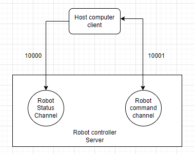
A TCP server runs in the robot controller to accept user-defined commands and return status data. This server uses ports 10000 and 10001 to interact with external clients, where:
10001 — used to send control commands to the robot and receive responses from the controller;
10000 — used to receive data returned by the robot (users can define the sending frequency and data content).
Users can carry out secondary development for the robot based on the JAKA TCP/IP protocol, and during development must note:
TCP/IP commands are executed asynchronously; the returned information only indicates that the controller has received the command, completed preprocessing and forwarding, and does not reflect the final execution result of the command. Some commands’ execution results require actively querying feedback data to obtain them;
Users need to implement the corresponding TCP client calls in accordance with this protocol, i.e., they must design the upper-level planner themselves to send robot data (servo_j, servo_p);
This function can be used simultaneously with the JAKA App without disconnecting the App from the controller. However, users must ensure that only one client can connect to port 10001; otherwise, the latter client may immediately replace the former.
Communication Port Data Description
Data sent from port 10001 and received from port 10000 is defined in JSON format. Users can quickly construct commands or parse feedback data according to the protocol.
Port 10001 Description
All commands in this manual fall into this category. All robot control commands are based on port 10001, and the port interaction data format is defined as follows:
Message sending format:
{"cmdName":"cmd","parameter1":"parameter2","parameter3":"parameter4",...}
Message receiving format:
{"cmdName":"cmd","errorCode":"0","errorMsg":"","parameter1":"parameter2","parameter3":"parameter4",...}
Port 10000 description
Port 10000 will return robot-related data in string format. The returned content can be referenced from the following example:
Note
Example:
{
    "len":Int,
    "drag_status":Bool,
    "extio":Object{...},
    "errcode":"0x0",
    "errmsg":"",
    "monitor_data":Array[6],
    "torqsensor":Array[2],
    "joint_actual_position":Array[6],
    "joint_position":Array[6],
    "actual_position":Array[6],
    "position":Array[6],
    "din":Array[144],
    "dout":Array[144],
    "ain":Array[66],
    "aout":Array[66],
    "tio_key":Array[3],
    "tio_din":Array[8],
    "tio_dout":Array[8],
    "tio_ain":Array[1],
    "task_state":Int,
    "homed":Array[9],
    "task_mode":Int,
    "interp_state":Int,
    "enabled":Bool,
    "paused":Bool,
    "rapidrate":Int,
    "current_tool_id":Int,
    "current_user_id":Int,
    "on_soft_limit":Int,
    "emergency_stop":Int,
    "drag_near_limit":Array[6],
    "funcdi":Array[15],
    "powered_on":Int,
    "inpos":Bool,
    "motion_mode":Int,
    "curr_tcp_trans_vel":Int,
    "protective_stop":Int,
    "point_key":Int,
    "netState":Int
}
Description:
len: The length of the data packet, generally not exceeding 15,000 bytes (depending on the data content).
drag_status: Boolean value indicating whether it is in drag mode.
extio: Configuration and status of the extended IO module, with the internal data structure as follows—
status: Status of all extended IO pins, including DI, DO, AI, AO.
status[0]: Status of all extended DI
status[1]: Status of all extended DO
status[2]: Status of all extended AI
status[3]: Status of all extended AO
setup: Array of all extended IO configurations, up to 8. Each extended IO module’s settings should follow the structure below—
setup[N][0]: Communication type. 0 represents Modbus RTU. 1 represents Modbus TCP/IP.
setup[N][0]=0:
setup[N][2][0]: Baud rate
setup[N][2][1]: Data bit length
setup[N][2][2]: Slave ID
setup[N][2][3]: Data bits
setup[N][2][4]: Parity bit
setup[N][2][5]: Stop bit length
setup[N][0]=1:
setup[N][2][0]: IP address
setup[N][2][1]: Port
setup[N][2][2]: Slave ID
setup[N][1]: Alias of the extended IO module.
setup[N][2]: Communication configuration, depending on communication type.
setup[N][3]: Pin configuration
setup[N][3][0][0]: Starting offset of registers in DI
setup[N][3][0][1]: [Number ]of DIs
setup[N][3][1][0]: Starting offset of registers in DO
setup[N][3][1][1]: [Number ]of DOs
setup[N][3][2][0]: Starting offset of registers in AI
setup[N][3][2][1]: Number of AIs
setup[N][3][3][0]: Starting offset of registers in AO
setup[N][3][3][1]: Number of AOs
num: Extended IO module.
pinmap: Pin diagram array of the extended IO module.
pinmap[N][0]: Starting offset of registers in DI for [N]
pinmap[N][1]: Starting offset of registers in DO for setup[N]
pinmap[N][2]: Starting offset of []registers in AI for setup[N]
pinmap[N][3]: Starting offset of [registers in AO ]for setup[N]
mode: Status of the extended IO module. 0 means the status is ON, 1 means OFF.
errcode: Hexadecimal string error code from the controller, such as “0x0”.
errmsg: Error message string from the controller, corresponding to errcode.
monitor_data: Monitoring data of the robot and cabinet for diagnostics.
monitor_data[0]: SCB major version number
monitor_data[1]: SCB minor version number
monitor_data[2]: Control cabinet temperature
monitor_data[3]: Control cabinet bus average power
monitor_data[4]: Control cabinet bus average current
monitor_data[5]: Monitoring data of robot joints 1–6 in the array
monitor_data[5][0]: Instantaneous current of robot joints
monitor_data[5][1]: Instantaneous voltage of robot joints
monitor_data[5][2]: Instantaneous temperature of robot joints
monitor_data[5][3]: Instantaneous average power
monitor_data[5][4]: Current fluctuation
monitor_data[5][5]: Accumulated laps
monitor_data[5][6]: Total operating time
monitor_data[5][7]: Operating cycles since the last startup
monitor_data[5][8]: Operating time since the last startup
monitor_data[5][9]: Joint torque
torqsensor: Torque settings and status array, data structure as follows—
torqsensor[0]: Sensor ID
torqsensor[1]: Current torque sensor settings
torqsensor[1][0]: Sensor brand
torqsensor[1][1]:Sensor pass filtering parameters
torqsensor[1][2]: Sensor load settings mass[, x, y, z]
torqsensor[1][3]: dead_zone_percent
torqsensor[1][4]:force_field_comp_method
torqsensor[1][5]: force_field_sample_no
torqsensor[1][6]: sensor_payload_id
torqsensor[1][7]: name of the sensor
torqsensor[1][8]: delete_on_next_start
torqsensor[1]: status of the torque sensor
torqsensor[1][0]: torque sensor status. 1 means working, 0 means off.
torqsensor[1][1]: torque sensor error code
torqsensor[1][2]: actual contact force of the torque sensor (6 dimensions)
torqsensor[1][3]: raw reading value of the torque sensor (6 dimensions)
joint_actual_position: actual positions of all 6 joints. Usually refers to servo actual feedback position.
joint_position: commanded positions of all 6 joints. (May have slight differences from the actual joint positions)
actual_position: actual position of the robot TCP in Cartesian space.
position: commanded position of the robot TCP in Cartesian space.
din: array of all digital input values.
dout: array of all digital output values in the cabinet.
ain: array of all analog input values in the cabinet.
aout: array of all analog output values in the cabinet.
tio_din: array of the status of all tool digital inputs.
tio_dout: array of the status of all tool digital outputs.
tio_ain: array of the status of all tool analog inputs.
task_state: indicator lights for power status and enable status. 1 means the robot is powered off, 2 means the robot is powered on, 3 means the robot is not enabled, 4 means the robot is enabled.
homed: Home status of each joint (deprecated).
task_mode: The robot’s task mode. 1 means manual mode, 2 means automatic mode, 3 means reserved mode, 4 means drag mode.
interp_state: Program status. 0 means idle, 1 means loading, 2 means paused, 3 means running.
enabled: Boolean value showing whether the robot is enabled.
paused: Boolean value showing whether the program is paused.
rapidrate: Scaling rate of robot movement.
current_tool_id: Index of the current TCP.
current_user_id: Index of the current user coordinate system.
on_soft_limit: Indicates whether it is at the soft limit, 0 means not reached, 1 means reached.
emergency_stop: Indicates whether the emergency stop button is pressed, 0 means not pressed, 1 means pressed.
drag_near_limit: Indicates whether each joint has been dragged close to its limit position, 0 means no, 1 means yes.
funcdi: Functional IO, see functional IO settings below.
powered_on: Power-on state, 0 means not powered on, 1 means powered on.
inpos: Motion state, true means motion completed, false means in motion.
motion_mode: Motion mode.
curr_tcp_trans_vel: Current end-effector movement speed of the robot.
protective_stop: Protective stop, 0 means no collision, 1 means collision.
point_key: Button status of the robot’s end-effector.
netState: Network connection status.
Configure optionalInfoConfig.ini
Because the robot controller’s factory default port 10000 returns all defined data fields, using TCP transmission will occupy large bandwidth and affect the timeliness of data reception on the client side.
In actual user applications, not all data is used, so this version adds the feature allowing users to configure which data fields are returned from port 10000.
The internal configuration file optionalInfoConfig.ini of the controller defines the data fields that the user can configure to enable or disable. When the value corresponding to a certain data field is 1, it means port 10000 will return this data field; when the value is 0, it will not return it.
The user can set and query the enable/disable status of this field through specific commands on port 10001 (click to check).
The detailed contents of the configuration file are as follows:
[ATTROPTIONALDATA]
joint_actual_position = 1
joint_position = 1
actual_position = 1
position = 1
din = 1
dout = 1
ain = 1
aout = 1
tio_key = 1
tio_din = 1
tio_dout = 1
tio_ain = 1
relay_io = 1
mb_slave_din = 1
mb_slave_dout = 1
mb_slave_ain = 1
mb_slave_aout = 1
pn_dev_din = 1
pn_dev_dout = 1
pn_dev_ain = 1
pn_dev_aout = 1
eip_adpt_din = 1
eip_adpt_dout = 1
eip_adpt_ain = 1
eip_adpt_aout = 1
task_state = 1
homed = 1
task_mode = 1
interp_state = 1
enabled = 1
paused = 1
rapidrate = 1
current_tool_id = 1
current_user_id = 1
on_soft_limit = 1
emergency_stop = 1
drag_near_limit = 1
funcdi = 1
powered_on = 1
inpos = 1
motion_mode = 1
curr_tcp_trans_vel = 1
protective_stop = 1
point_key = 1
motion_line = 1
err_add_line = 1

[STATOPTIONALDATA]
drag_status = 1
num = 1
setup = 1
pinmap = 1
mode = 1
status = 1
extio = 1
errcode = 1
errmsg = 1
monitor_data = 1
torqsensor = 1

[PORTCONFIG]
port10000_delay_ms = 2000
For the data in
ATTROPTIONALDATAandSTATOPTIONALDATA, setting it to 0 means port 10000 will not send this data; setting it to 1 means port 10000 will send this data.For port10000_delay_ms in PORTCONFIG, its value represents the data sending cycle of port 10000 (unit: ms).
Warning
Please note: The data the user obtains from port 10000 is not real-time; the actual sending cycle is affected by network fluctuations and other factors.
In addition, excessively large data or too rapid sending cycles can easily cause network congestion, packet sticking, and other issues (especially during network fluctuations), leading to data reception or parsing failures on the user side.
Please try to exclude unnecessary data and set a reasonable sending cycle.
About the Robot Orientation
All robot spatial orientation involved in the JAKA TCP/IP control protocol adopt RPY angle representation.
In RPY, the rotation transformation sequence is rotation around the fixed coordinate system axes x-y-z in order. Rotation around the fixed coordinate system z-axis (Rz) is called Roll; rotation around the fixed coordinate system y-axis (Ry) is called Pitch; rotation around the fixed coordinate system x-axis (Rx) is called Yaw.
The robot pose data format is defined as[ X , Y , Z , Rx , Ry , Rz], where X, Y, Z represent positions on the three coordinate axes in millimeters; Rx, Ry, Rz represent the robot posture, corresponding respectively to the three RPY components Yaw, Pitch, and Roll, in degrees.
Regarding the conversion relationship with the rotation matrix, suppose we select a fixed coordinate system {A}, the RPY representation of a certain coordinate system {B} and its conversion with the rotation matrix is calculated as follows:

User Precautions
Error code description
When the interface returns correctly, errorCode should be 0 (either int or string type) instead of Empty/Null; when errorCode is other than 0, it indicates an execution error.
If an error occurs, the client can check errorCode and msg in the returned JSON data
When the value returned by errorCode is 0, the message returned by errorMsg is empty, indicating successful execution;
When the value returned by errorCode is other numbers, errorMsg will return specific error information, indicating that an exception occurred in the program.
Error Code Short Lists
Basic Robot Operations (200-249)
ERROR_INSTALLATION_ANGLE_OUT_OF_RANGE=”0x000200” #installation angle out of range
Move Commands (250-349)
ERROR_SETTING_MOTION_PLANNER=”0x000250”
Drag and force control
FTP part
TIO part
Reserved for future features
Other notes
errorCode may be a string or an integer.
All commands are non-blocking commands.
The units used by the protocol are: mm (millimeters) and degree (angles).
TCP IO index starts from 1, but SDK IO index starts from 0.
Ports 10000 and 10004 settings
Port 10004 is a dedicated SDK port, with returned data identical to port 10000.
Get the sending cycle of port 10000
Send message:
{"cmdName":"get_port10000_delay_ms"}
Receive message:
{"errorCode": "0", "errorMsg": "", "cmdName": "get_port10000_delay_ms", "port10000_delay_ms": 2000}
Modify the sending cycle of port 10000
Send message:
{"cmdName":"set_port10000_delay_ms","port10000_delay_ms":20}
Receive message:
{"errorCode": "0", "errorMsg": "", "cmdName": "set_port10000_delay_ms"}
Query the configuration of optionalInfoConfig
Send message:
{"cmdName":"getOptionalInfoConfig","section":"PORTCONFIG","key":"port10000_delay_ms"}
Receive message:
{"errorCode": "0", "errorMsg": "", "cmdName": "getOptionalInfoConfig", "value": 20}
Send message:
{"cmdName":"getOptionalInfoConfig","section":"ATTROPTIONALDATA","key":"joint_actual_position"}
Receive message:
{"errorCode": "0", "errorMsg": "", "cmdName": "getOptionalInfoConfig", "value": 1}
Modify the configuration of optionalInfoConfig
Send message:
{"cmdName":"setOptionalInfoConfig","section":"PORTCONFIG","key":"port10000_delay_ms", "value": "200"}
Receive message:
{"errorCode": "0", "errorMsg": "", "cmdName": "setOptionalInfoConfig"}
Send message:
{"cmdName":"setOptionalInfoConfig","section":"ATTROPTIONALDATA","key":"joint_actual_position", "value": 0}
Receive message:
{"errorCode": "0", "errorMsg": "", "cmdName": "setOptionalInfoConfig"}
Instruction interface introduction
The following describes the usage of each instruction by function module section, with the meaning of return fields explained under each instruction.
Basic robot operations
Turn on power
Send message:
{"cmdName":"power_on"}
Receive message:
{"errorCode": "0", "errorMsg": "", "cmdName": "power_on"}
Turn off power
Send message:
{"cmdName":"power_off"}
Receive message:
{"errorCode": "0", "errorMsg": "", "cmdName": "power_off"}
Enable robot
Send message:
{"cmdName":"enable_robot"}
Receive message:
{"errorCode": "0", "errorMsg": "", "cmdName": "enable_robot"}
Disable robot
Send message:
{"cmdName":"disable_robot"}
Receive message:
{"errorCode": "0", "errorMsg": "", "cmdName": "disable_robot"}
Shut down the robot and controller
Send message:
{"cmdName":"shutdown"}
Receive message:
null
After sending the shutdown command, the controller closes processes, the TCP server closes, and therefore no message is returned.
Robot State
Send message:
{"cmdName":"get_robot_state"}
Receive message:
{"enable": true, "power": 1, "errorMsg": "", "errcode": 0, "cmdName": "get_robot_state", "errorCode": "0", "msg": ""}
Description:
enable: Indicates the enable status of the robot, true means enabled, false means not enabled.
power: Indicates the power-on status of the robot, 1 means powered on, 0 means not powered on.
errorCode: Indicates the error code corresponding to the TCP command.
errcode: Indicates the corresponding error code returned by the controller.
errorMsg: Indicates the error message corresponding to the TCP command.
msg: Indicates the corresponding error message returned by the controller.
Get controller version
Send message:
{"cmdName":"get_version"}
Receive message:
{"errorMsg": "", "cmdName": "get_version", "errorCode": "0", "robot_name": "JKROBOT", "version": "1.7.1_40_rc_X64", "robot_id": "Zu20200100"}
Description:
robot_name: Robot name
version: Robot controller version
robot_id: Robot serial number
Get robot installation angle
Send message:
{"cmdName":"get_installation_angle"}
Receive message:
{"installation_angle": [[x, y, z, w], [rx, ry , rz]], "errorCode": "0", "cmdName": "get_installation_angle", "errorMsg": ""}
Description:
x, y, z, w: Installation angle represented as quaternion.
rx, ry, rz: Installation angle represented as Euler angles.
Set robot installation angle
Send message:
{"cmdName":"set_installation_angle","angleX":angleX,"angleZ": angleZ}
Receive message:
{"errorCode": "0", "errorMsg": "", "cmdName": "set_installation_angle"}
Description:
angleX: Robot’s rotation angle in the X direction, range[ 0 to 180 ]degrees.
angleZ: Robot’s rotation angle in the Z direction, range [0, 360) degrees.
Set robot manual/automatic mode
Send message:
{"cmdName":"set_auto_manual_mode", "mode":0}
Receive message:
{"cmdName": "set_auto_manual_mode", "errorCode": "0", "errorMsg": ""}
Description:
mode: 0 for manual mode, 1 for automatic mode
Get robot manual/automatic mode
Send message:
{"cmdName":"get_auto_manual_mode"}
Receive message:
{"mode": 1, "cmdName": "get_auto_manual_mode", "errorCode": "0", "errorMsg": ""}
Description:
mode: 0 for manual mode, 1 for automatic mode
Set robot vibration suppression mode
Send message:
{"cmdName": "enable_vibsuppress_override","mode": 1}
Receive message:
{"cmdName": "enable_vibsuppress_override", "errorCode": "0", "errorMsg": ""}
Description:
mode: 0: Off, 1: Mode 1, 2: Mode 2
The initial default frequency for each model is shown in the table below:
Load/Model |
Default frequency (Hz) |
|---|---|
MiniCobot1 |
16 |
MiniCobot2 |
15 |
3kg (Zu3 and similar) |
14 |
5kg (C5/A5/Dual-arm and similar) |
12 |
7kg (Zu7 and similar) |
12 |
12kg (Zu12 and similar) |
8 |
16kg(Zu16) |
7.5 |
18kg(Zu18) |
7.5 |
20kg(Zu20) |
7.5 |
30kg(Zu30) |
7.4 |
Max40 |
5 |
Enable vibration suppression settings
Send message:
{"cmdName": "vib_suppress_on", "frequency": 12}
Receive message:
{"cmdName": "vib_suppress_on", "errorCode": "0", "errorMsg": ""}
Description:
frequency: Vibration frequency
Disable vibration suppression settings
Send message:
{"cmdName": "vib_suppress_off"}
Receive message:
{"cmdName": "vib_suppress_off", "errorCode": "0", "errorMsg": ""}
Troubleshooting
Introduction to troubleshooting methods
When encountering issues during the use of the JAKA TCP/IP control protocol, you can refer to the following steps for troubleshooting:
Confirm that the network connection between the client and the robot controller IP address is normal;
For abnormalities in TCP/IP command calls, determine the relevant error information based on the return value and returned error message;
Obtain the robot system error code and error message from the feedback data on port 10000 to troubleshoot related abnormalities;
You can also troubleshoot robot system issues by connecting with the robot APP. During troubleshooting, you can deploy a network debugging tool or Wireshark on the client to analyze relevant data.
Introduction to common TCP/IP issues
If, during actual development and testing, you encounter issues such as commands not returning, it is recommended to use a network debugging assistant to connect to the robot server: IP is the robot IP, port number is fixed at 10000 or 100001, to check if the robot server is functioning normally; if it is normal, please check whether there are errors in the code.
During actual usage, when connecting to port 10000, it is found that each received packet is incomplete and only partially received;
For such situations, it is recommended to check the size of the client socket’s receive buffer, as it may be set smaller than the packet size returned by port 10000, resulting in incomplete reception.
Data push frequency is too low and not timely.
For such situations, it is recommended to check the server’s port data refresh frequency, such as port10000_delay_ms in optionalconfig mentioned at the beginning, to see if it is set appropriately.
User feedback
If there are any errors or unclear descriptions in the document, or if you have any comments or suggestions, please send an email to support@jaka.com and we will reply to you as soon as possible.