

'%3e%3cpath%20id='路径_20862'%20data-name='路径%2020862'%20d='M15,26A11,11,0,1,0,4,15,11,11,0,0,0,15,26Z'%20fill='none'%20stroke='%23333'%20stroke-width='1.5'/%3e%3cpath%20id='路径_20863'%20data-name='路径%2020863'%20d='M6,19.173q2.171.871,3.126,0c.955-.871.131-3.513,1.468-4.242s3.374,2.5,5.279,1.439-.179-3.9,1.142-5.047,3.04.147,3.34-1.775-1.4-1.088-1.728-2.9q-.327-1.816,0-1.91'%20transform='translate(-0.9%20-0.331)'%20fill='none'%20stroke='%23333'%20stroke-linecap='round'%20stroke-width='1.5'/%3e%3cpath%20id='路径_20864'%20data-name='路径%2020864'%20d='M28.033,36.511q-1.546-1.582-1.113-2.942c.433-1.359,1.147-1.279,1.459-2.12s-.568-2.038,1.384-3.061q1.952-1.023,5.367,2.371'%20transform='translate(-10.271%20-10.868)'%20fill='none'%20stroke='%23333'%20stroke-linecap='round'%20stroke-width='1.5'/%3e%3c/g%3e%3c/svg%3e) English Global
English Global


Segmented Industries
Application Cases


Attention
'%3e%3cline%20id='直线_13422'%20data-name='直线%2013422'%20x2='29.367'%20transform='translate(23668.262%20-12026.238)%20rotate(45)'%20fill='none'%20stroke='%23000'%20stroke-linecap='round'%20stroke-width='2'/%3e%3cline%20id='直线_13423'%20data-name='直线%2013423'%20x2='29.367'%20transform='translate(23689.027%20-12026.238)%20rotate(135)'%20fill='none'%20stroke='%23000'%20stroke-linecap='round'%20stroke-width='2'/%3e%3c/g%3e%3c/svg%3e)
Cancel
OK
English Global
'%3e%3cpath%20id='路径_21753'%20data-name='路径%2021753'%20d='M25.248,22.5A8.248,8.248,0,1,0,17,14.248,8.248,8.248,0,0,0,25.248,22.5Z'%20transform='translate(-0.33%20-1.695)'%20fill='none'%20stroke='%23000'%20stroke-linecap='round'%20stroke-linejoin='round'%20stroke-width='4'/%3e%3cpath%20id='路径_21754'%20data-name='路径%2021754'%20d='M6,41.453v1.261H43.837V41.453c0-4.709,0-7.064-.916-8.862a8.409,8.409,0,0,0-3.675-3.675C37.448,28,35.093,28,30.384,28H19.453c-4.709,0-7.064,0-8.862.916a8.408,8.408,0,0,0-3.675,3.675C6,34.39,6,36.744,6,41.453Z'%20transform='translate(0%201.209)'%20fill='none'%20stroke='%23000'%20stroke-linecap='round'%20stroke-linejoin='round'%20stroke-width='4'/%3e%3c/g%3e%3c/svg%3e)


Change Password
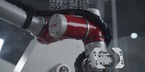
Integrating Cobot with Existing PLC Systems: A Technical Guide
'%3e%3cpath%20id='路径_20744'%20data-name='路径%2020744'%20d='M5,19H22.665v9.762a.93.93,0,0,1-.93.93H5.93a.93.93,0,0,1-.93-.93Z'%20transform='translate(0%20-8.027)'%20fill='none'%20stroke='%23999'%20stroke-linejoin='round'%20stroke-width='1.5'/%3e%3cpath%20id='路径_20745'%20data-name='路径%2020745'%20d='M5,7.93A.93.93,0,0,1,5.93,7H21.735a.93.93,0,0,1,.93.93v4.649H5Z'%20transform='translate(0%20-1.605)'%20fill='none'%20stroke='%23999'%20stroke-linejoin='round'%20stroke-width='1.5'/%3e%3cpath%20id='路径_20746'%20data-name='路径%2020746'%20d='M16,4V7.719'%20transform='translate(-5.886)'%20fill='none'%20stroke='%23999'%20stroke-linecap='round'%20stroke-linejoin='round'%20stroke-width='1.5'/%3e%3cpath%20id='路径_20747'%20data-name='路径%2020747'%20d='M32,4V7.719'%20transform='translate(-14.449)'%20fill='none'%20stroke='%23999'%20stroke-linecap='round'%20stroke-linejoin='round'%20stroke-width='1.5'/%3e%3cpath%20id='路径_20748'%20data-name='路径%2020748'%20d='M28,34h2.789'%20transform='translate(-12.308%20-16.054)'%20fill='none'%20stroke='%23999'%20stroke-linecap='round'%20stroke-linejoin='round'%20stroke-width='1.5'/%3e%3cpath%20id='路径_20749'%20data-name='路径%2020749'%20d='M14,34h2.789'%20transform='translate(-4.816%20-16.054)'%20fill='none'%20stroke='%23999'%20stroke-linecap='round'%20stroke-linejoin='round'%20stroke-width='1.5'/%3e%3cpath%20id='路径_20750'%20data-name='路径%2020750'%20d='M28,26h2.789'%20transform='translate(-12.308%20-11.773)'%20fill='none'%20stroke='%23999'%20stroke-linecap='round'%20stroke-linejoin='round'%20stroke-width='1.5'/%3e%3cpath%20id='路径_20751'%20data-name='路径%2020751'%20d='M14,26h2.789'%20transform='translate(-4.816%20-11.773)'%20fill='none'%20stroke='%23999'%20stroke-linecap='round'%20stroke-linejoin='round'%20stroke-width='1.5'/%3e%3c/g%3e%3c/svg%3e) 2025.12.29 Blog
2025.12.29 BlogShare:


Connecting a new cobot to an established production line's control architecture is a critical step. Success in this integration ensures the robotic cell functions as a synchronized component rather than an isolated unit. We approach this process by focusing on three sequential technical phases: establishing clear communication, mapping input and output signals, and implementing coordinated safety protocols. This methodology applies whether integrating a lightweight cobot or a more robust industrial robot arm into your system.
Establishing a Reliable Communication Protocol
The initial phase involves creating a digital link between the robot controller and the central PLC. The choice of protocol is determined by your existing infrastructure. Common industrial protocols like PROFINET, EtherNet/IP, or Modbus TCP are typically supported. This network connection forms the data highway. The configuration requires setting matching IP addresses, defining device names within the network topology, and ensuring the data exchange cycle time aligns with the required speed of your process. A stable, low-latency connection here is fundamental, as it carries all subsequent command and status signals between the PLC’s logic and the industrial robot arm’s motion controller.
Configuring Discrete and Analog Signal Exchange
With communication established, the next step is defining the specific data points to be shared. This is typically managed through a mapped set of digital inputs/outputs and possibly analog or register addresses. Standard practice involves the PLC using a discrete output signal to command the cobot to start a specific program or resume motion after an interruption. Conversely, the robot uses digital outputs to signal its status—such as “Program Running,” “Fault Active,” or “Cycle Complete”—back to the PLC. For more complex data, like selecting a variable from a recipe, integer values can be passed through designated registers. Precise mapping documentation for these signals is essential for both programming teams and future troubleshooting.
Implementing Unified Safety and Control Logic
The final integration layer ensures safe and logical interoperability. Safety signals must be hardwired or communicated via a safety-rated fieldbus to meet relevant standards. This often involves connecting the industrial robot arm’s safety-rated stop outputs to the safety PLC and wiring the safety gate or emergency stop circuits into the robot’s safety inputs. Beyond safety, the operational logic must be coordinated. The PLC should orchestrate the overall sequence, managing conveyors and peripherals, while issuing concise commands to the cobot. The robot’s controller then executes its precise motion tasks and reports back. This clear division of responsibility prevents logic conflicts and simplifies program maintenance.
Successfully linking a cobot to a PLC system is a structured process of network configuration, signal mapping, and logic coordination. When executed methodically, it results in a cell where automation components work in unison under centralized control. Our design philosophy at JAKA emphasizes straightforward connectivity and transparent signal handling across our range of systems, supporting engineers in creating these reliable and efficient integrated workcells.
'%3e%3cpath%20id='路径_17618'%20data-name='路径%2017618'%20d='M10.031,8,6,11.455l4.031,4.031'%20fill='none'%20stroke='%23333'%20stroke-linecap='round'%20stroke-linejoin='round'%20stroke-width='2'/%3e%3cpath%20id='路径_17619'%20data-name='路径%2017619'%20d='M6,14H19.24a7.486,7.486,0,1,1,0,14.971H9.454'%20transform='translate(0%20-2.545)'%20fill='none'%20stroke='%23333'%20stroke-linecap='round'%20stroke-linejoin='round'%20stroke-width='2'/%3e%3c/g%3e%3c/svg%3e)
'%3e%3cpath%20id='路径_17618'%20data-name='路径%2017618'%20d='M10.031,8,6,11.455l4.031,4.031'%20fill='none'%20stroke='%23fff'%20stroke-linecap='round'%20stroke-linejoin='round'%20stroke-width='2'/%3e%3cpath%20id='路径_17619'%20data-name='路径%2017619'%20d='M6,14H19.24a7.486,7.486,0,1,1,0,14.971H9.454'%20transform='translate(0%20-2.545)'%20fill='none'%20stroke='%23fff'%20stroke-linecap='round'%20stroke-linejoin='round'%20stroke-width='2'/%3e%3c/g%3e%3c/svg%3e) Return to List
Return to List


Customer Service Hotline :
400-006-2665
Whatsapp:+8618501781175
Company Email:
Company Address:
United States: 3401 E Harbour Dr, Phoenix, AZ 85034, United States
Germany: Breslauer Str. 10, 90766 Fuerth, Germany
Japan:1F, 1 - 6 - 14 Aoi, Higashi, Nagoya , Japan
Malaysia:5-G, Jalan Borealis 3, Bandar Cassia,14110 Simpang Ampat, Penang,Malaysia
China:18 Nangu Road, Minhang District, Shanghai, China
Germany: Breslauer Str. 10, 90766 Fuerth, Germany
Japan:1F, 1 - 6 - 14 Aoi, Higashi, Nagoya , Japan
Malaysia:5-G, Jalan Borealis 3, Bandar Cassia,14110 Simpang Ampat, Penang,Malaysia
China:18 Nangu Road, Minhang District, Shanghai, China
Copyright©2023JAKA Robotics Co., Ltd. All rights reserved 沪ICP备15045540号-2 沪公网安备31011202008960号
'%3e%3ccircle%20id='椭圆_7060'%20data-name='椭圆%207060'%20cx='50'%20cy='50'%20r='50'%20transform='translate(134%209657)'%20fill='%23d80c1e'/%3e%3cpath%20id='路径_21623'%20data-name='路径%2021623'%20d='M947.11,3321.132s-4.227,8.162,4.833,24.7c.065.116.129.23.195.346s.124.234.187.354c9.06,16.532,18.214,17.362,18.214,17.362a4.8,4.8,0,0,0,2.246-.177,17.018,17.018,0,0,0,4.229-2.687c1.79-1.639.384-5.317-.541-7.009-1.876-3.422-4.162-4.65-5.447-4.225-.577.188-3.1,1.7-3.1,1.7a2.855,2.855,0,0,1-1.86.213s-3.357-.941-7.792-8.892c-4.309-8.01-3.3-11.347-3.3-11.347a2.854,2.854,0,0,1,1.182-1.455s3.069-1.675,3.1-1.7c1.229-.863.555-4.1-.63-6.864a6.434,6.434,0,0,0-3.163-3.754c-2.256-1.158-7.477.768-8.349,3.436Z'%20transform='translate(-778%206368.353)'%20fill='%23fff'/%3e%3c/g%3e%3c/svg%3e)
Customer Service Hotline
400-006-2665Company Email:
Company Address:
United States: 3401 E Harbour Dr, Phoenix, AZ 85034, United States
Germany: Breslauer Str. 10, 90766 Fuerth, Germany
Japan:1F, 1 - 6 - 14 Aoi, Higashi, Nagoya , Japan
Malaysia:5-G, Jalan Borealis 3, Bandar Cassia,14110 Simpang Ampat, Penang,Malaysia
China:18 Nangu Road, Minhang District, Shanghai, China
Germany: Breslauer Str. 10, 90766 Fuerth, Germany
Japan:1F, 1 - 6 - 14 Aoi, Higashi, Nagoya , Japan
Malaysia:5-G, Jalan Borealis 3, Bandar Cassia,14110 Simpang Ampat, Penang,Malaysia
China:18 Nangu Road, Minhang District, Shanghai, China


'%3e%3cpath%20id='路径_21594'%20data-name='路径%2021594'%20d='M-993.748,3818.961h0a8.127,8.127,0,1,0-16.25,0'%20transform='translate(-0.958%200)'%20fill='none'%20stroke='%23d80c1e'%20stroke-linecap='round'%20stroke-linejoin='round'%20stroke-width='1'/%3e%3cpath%20id='路径_21595'%20data-name='路径%2021595'%20d='M-987.315,3834.607h0a6.421,6.421,0,0,1-6.421,6.421h-.153'%20transform='translate(-7.391%20-9.576)'%20fill='none'%20stroke='%23d80c1e'%20stroke-linecap='round'%20stroke-linejoin='round'%20stroke-width='1'/%3e%3crect%20id='矩形_48952'%20data-name='矩形%2048952'%20width='2.883'%20height='6.026'%20rx='1.442'%20transform='translate(-996.148%203818.961)'%20fill='none'%20stroke='%23d80c1e'%20stroke-linecap='round'%20stroke-linejoin='round'%20stroke-width='1'/%3e%3crect%20id='矩形_48953'%20data-name='矩形%2048953'%20width='2.883'%20height='6.026'%20rx='1.442'%20transform='translate(-1012.397%203818.961)'%20fill='none'%20stroke='%23d80c1e'%20stroke-linecap='round'%20stroke-linejoin='round'%20stroke-width='1'/%3e%3crect%20id='矩形_48954'%20data-name='矩形%2048954'%20width='3.07'%20height='2.291'%20rx='1.146'%20transform='translate(-1004.35%203830.306)'%20fill='none'%20stroke='%23d80c1e'%20stroke-linecap='round'%20stroke-linejoin='round'%20stroke-width='1'/%3e%3c/g%3e%3c/svg%3e)
'%3e%3cpath%20id='路径_21594'%20data-name='路径%2021594'%20d='M-993.748,3818.961h0a8.127,8.127,0,1,0-16.25,0'%20transform='translate(-0.958%200)'%20fill='none'%20stroke='%23fff'%20stroke-linecap='round'%20stroke-linejoin='round'%20stroke-width='1'/%3e%3cpath%20id='路径_21595'%20data-name='路径%2021595'%20d='M-987.315,3834.607h0a6.421,6.421,0,0,1-6.421,6.421h-.153'%20transform='translate(-7.391%20-9.576)'%20fill='none'%20stroke='%23fff'%20stroke-linecap='round'%20stroke-linejoin='round'%20stroke-width='1'/%3e%3crect%20id='矩形_48952'%20data-name='矩形%2048952'%20width='2.883'%20height='6.026'%20rx='1.442'%20transform='translate(-996.148%203818.961)'%20fill='none'%20stroke='%23fff'%20stroke-linecap='round'%20stroke-linejoin='round'%20stroke-width='1'/%3e%3crect%20id='矩形_48953'%20data-name='矩形%2048953'%20width='2.883'%20height='6.026'%20rx='1.442'%20transform='translate(-1012.397%203818.961)'%20fill='none'%20stroke='%23fff'%20stroke-linecap='round'%20stroke-linejoin='round'%20stroke-width='1'/%3e%3crect%20id='矩形_48954'%20data-name='矩形%2048954'%20width='3.07'%20height='2.291'%20rx='1.146'%20transform='translate(-1004.35%203830.306)'%20fill='none'%20stroke='%23fff'%20stroke-linecap='round'%20stroke-linejoin='round'%20stroke-width='1'/%3e%3c/g%3e%3c/svg%3e)


'%3e%3cpath%20id='路径_21593'%20data-name='路径%2021593'%20d='M-971.813,3958.813l5.517-5.517,5.517,5.517'%20fill='none'%20stroke='%23d80c1e'%20stroke-linecap='round'%20stroke-linejoin='round'%20stroke-width='1'/%3e%3cline%20id='直线_13976'%20data-name='直线%2013976'%20y2='15.981'%20transform='translate(-966.296%203953.296)'%20fill='none'%20stroke='%23d80c1e'%20stroke-linecap='round'%20stroke-linejoin='round'%20stroke-width='1'/%3e%3cline%20id='直线_13977'%20data-name='直线%2013977'%20x2='8.519'%20transform='translate(-970.556%203952.778)'%20fill='none'%20stroke='%23d80c1e'%20stroke-linecap='round'%20stroke-linejoin='round'%20stroke-width='1'/%3e%3c/g%3e%3c/svg%3e)
'%3e%3cpath%20id='路径_21593'%20data-name='路径%2021593'%20d='M-971.813,3958.813l5.517-5.517,5.517,5.517'%20fill='none'%20stroke='%23fff'%20stroke-linecap='round'%20stroke-linejoin='round'%20stroke-width='1'/%3e%3cline%20id='直线_13976'%20data-name='直线%2013976'%20y2='15.981'%20transform='translate(-966.296%203953.296)'%20fill='none'%20stroke='%23fff'%20stroke-linecap='round'%20stroke-linejoin='round'%20stroke-width='1'/%3e%3cline%20id='直线_13977'%20data-name='直线%2013977'%20x2='8.519'%20transform='translate(-970.556%203952.778)'%20fill='none'%20stroke='%23fff'%20stroke-linecap='round'%20stroke-linejoin='round'%20stroke-width='1'/%3e%3c/g%3e%3c/svg%3e)
Contact Us