JAKA SRCI User Manual
Abbreviation
Abbreviation |
Description |
|---|---|
SRCI |
Standard Robot Command Interface |
EDK |
Easy Development Kit, a SRCI protocol parser provided by Siemens. |
RI |
Robot Interface, the status of which indicates if the SRCI communication has already been established. |
RA |
Robot Arm |
RC |
Robot Controller |
TCP |
Tool Center Point |
TCS |
Tool Coordinate System |
UCS |
User Coordinate System |
WCS |
World Coordinate System |
WCP |
Wrist Center Point |
M/O |
Mandatory/Optional |
Introduction
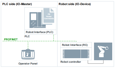
SRCI is an open standard protocol developed and maintained by PROFINET International. SRCI runs over the PROFINET industrial Ethernet-based communication protocol, therefore SRCI deployment and use requires PROFINET. SRCI offloads the complete integration of a robotic application, including programming, to the PLC. SRCI in essence provides an interface that allows users to program and control a robot directly in a PLC. SRCI standardizes the use of data packets and PLC libraries, enabling users to freely and rapidly switch between different robots without having to re-learn, re-program and re-deploy.
Note:
The level of supported SRCI functions and parameters is determined by the type of SRCI certification the released version of the SRCI interpreter has achieved (i.e Limited Release or Broad Release). JAKA’s interpreter has been certified for Broad Release and supports all parameters and functions that are included within the “Profile:Core”. Please read the following content carefully, and pay special attention to the Risks part.
Hardware and Software Check
JAKA side
Robot Hardware: no limit(please switch PROFINET ON).
The PROFINET GSDML must be upgraded to GSDML-V2.41-JAKA-JAKARobot-20231017.xml.
Robot Controller: v3.3.13 and above (the controller must be X64 version).
App: v3.3.7 and above.
PLC side
Siemens SIMATIC S7-1500 PLC and above, for example: Siemens 1516-3 PN/DP.
The utilized PLC must support PROFINET.
Functions Supported on Different Versions
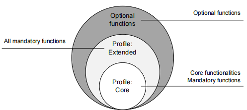
SRCI defines 3 function groups, which contain the functions of all interfaces:
Profile Core |
Profile Extended |
Profile Optional |
|---|---|---|
Contains core functions of the interface / Contains basic commands |
Contains all mandatory commands that are not featured by Profile Core |
Contains all optional functions |
“Profile: Core” supported functions and parameters
The list below details the functions supported by JAKA’s Broad Release certified “Profile: Core” interpreter:
ChangeSpeedOverrideEnableRobotExchangeConfigurationGroupContinueGroupInterruptGroupJogGroupResetGroupStopMoveAxesAbsoluteMoveDirectAbsoluteMoveLinearAbsoluteReadActualPositionReadActualPositionCyclicReadToolDataReadFrameDataReadLoadDataReadMessagesReadRobotDataReadRobotDefaultDynamicsReadRobotReferenceDynamicsReadRobotSWLimitsReturnToPrimarySetOperationModeSetSequenceWriteToolDataWriteFrameDataWriteLoadDataWriteRobotDefaultDynamicsWriteRobotReferenceDynamicsWriteRobotSWLimits
Limitations
Please read through these limitations before using SRCI commands:
When using the MoveLinearAbsolute command, if the ConfigMode of the target point is inconsistent with that of the current point, it will become unreachable and the enable will be disabled.
When using the WriteRobotSWLimits instruction, the manual/automatic mode will be switched. Try to set it in external T1 mode.
LoadData[0] is the default and cannot be set via WriteLoadData. If the default load on the app is not zero, the data of LoadData[0] will fail to synchronize.
Unsupported functions:
CreateServerLog
ReadServerLog
CreateClientLog
ReadClientLog
Part of UserData function: DelayTime, InterpreterCycleTime, Accelerating, ConstantVelocity, IsBlending
Risks
JAKA Safety IO
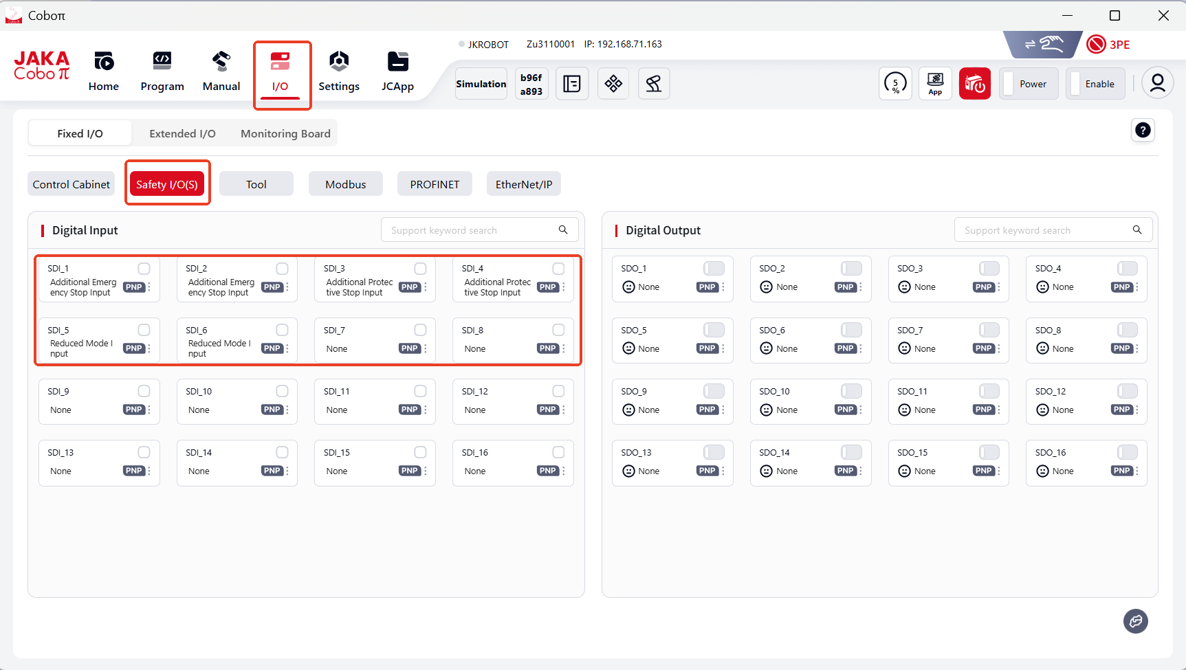
Work with JAKA safety IO functions to ensure operator safety. JAKA’s SRCI interpreter supports the following safety functions(external safety IO):
Additional emergency-stop
Additional protective-stop
Reduced mode(able to set robot TCP speed, power limit, etc. )
Commands Descriptions
Note:
√: supported as SRCI required. ×: not supported. !: supported with conditions.
ChangeSpeedOverride
ChangeSpeedOverride affects all move commands except GroupJog and FreeDrive.
Can be set during a movement.
Automatically reverts to 5% of the allowed speed after RI initialization.
Inputs
Parameter |
Data Type |
Unit |
M/O |
Note |
|---|---|---|---|---|
Override |
REAL |
[%] |
M |
√ |
EnableRobot
JAKA allows to Power On/Off and Enable/Disable the robot separately.
Power On the robot before Enable; Disable the robot before Power Off.
Enabling the robot means that the robot is ready to receive commands.
In normal conditions, the EnableRobot command takes 5 seconds to take effect.
However in a situation where the robot is in an emergency stop state, 5 seconds extend to 20 seconds. This is because Powering On the robot is the prerequisite for Enabling the robot. In normal conditions, Power On has been completed during the first enable, so the user can directly Enable the robot to assume its control. In a situation of an emergency stop taking effect, the robot is in a power-off state, and it will not automatically power back on. Therefore when the Enable command is send again, the robot will first Power On itself (during the first 15 seconds) and then the Enable command will be executed (in the remainig 5 seconds).
Inputs
Parameter |
Data Type |
Unit |
M/O |
Note |
|---|---|---|---|---|
HoldToRun |
BOOL |
|
M |
√ |
StepMode |
USINT |
|
M |
! Only support 0 and 2 |
ManualStep |
BOOL |
|
M |
√ |
Outputs
Parameter |
Data Type |
Unit |
M/O |
Note |
|---|---|---|---|---|
Enabled |
BOOL |
|
M |
√ |
GroupContinue
This function can continue executing an “interrupted” move command.
GroupInterrupt
This function interrupts all active commands and stops all joints. Yet the planned trajectory will remain, which could be resumed by GroupContinue.
JAKA supports jogging when GroupInterrupt, and sequence 2 may use automatically.
GroupStop has higher priority than GroupInterrupt, which would end GroupInterrupt when called.
GroupJog
GroupJog includes: JogFrame, JogTool and JogAxes.
JAKA supports them all.
GroupReset
It deletes all messages read by ReadMessages, including errors and warnings.
The main scenarios:
controller error, like pstop (protective-stop)
the AddOn’s SRCI malfunctions
GroupStop
Clear the move commands for the current active sequence and empty the move command cache.
MoveAxesAbsolute
This function commands a movement of the robot without a defined path.
Inputs
Parameter |
Data Type |
Unit |
M/O |
Note |
|---|---|---|---|---|
JointPosition |
RobotJointPosition |
|
M |
!not support external axis |
VelocityRate |
REAL |
[%] |
M |
√ |
AccelerationRate |
REAL |
[%] |
M |
√ |
DecelerationRate |
REAL |
[%] |
O |
× |
JerkRate |
REAL |
[%] |
O |
× |
ToolNo |
USINT |
|
M |
support 0-15, default 0: flange |
AbortingMode |
USINT |
|
M |
√ |
BlendingMode |
USINT |
|
M |
!refer to blending sectoin |
BlendingParameter |
ARRAY[0..1] of REAL |
|
M |
√ |
MoveDirectAbsolute
This function calculates the fastest path to the target position (joint position) based on the provided Cartesian coordinates, with the target position calculated according to the ConfigMode’s ConfigParameters.
Inputs
Parameter |
Data Type |
Unit |
M/O |
Note |
|---|---|---|---|---|
Position |
RobotCartesian Position |
|
M |
!not support external axis |
VelocityRate |
REAL |
[%] |
M |
√ |
AccelerationRate |
REAL |
[%] |
M |
√ |
DecelerationRate |
REAL |
[%] |
O |
× |
JerkRate |
REAL |
|
O |
× |
ToolNo |
USINT |
|
M |
support 0-15, default 0: flange, -1: current |
FrameNo |
USINT |
|
M |
support 0-15, default 0: World, -1: current |
AbortingMode |
USINT |
|
M |
√ |
BlendingMode |
USINT |
|
M |
!refer to blending sectoin |
ConfigMode |
ConfigParameters |
|
M |
!refer to mechanical constraction sectoin |
TurnMode |
USINT |
|
M |
! Only support 2 |
MoveLinearAbsolute
This function commands an interpolated linear movement on the robot arm from the actual position of the TCP to an absolute cartesian position in the specified coordinate system.
Inputs
Parameter |
Data Type |
Unit |
M/O |
Note |
|---|---|---|---|---|
Position |
RobotCartesian Position |
|
M |
!not support external axis |
VelocityRate |
REAL |
[%] |
M |
√ |
AccelerationRate |
REAL |
[%] |
M |
√ |
DecelerationRate |
REAL |
[%] |
O |
× |
JerkRate |
REAL |
|
O |
× |
ToolNo |
USINT |
|
M |
support 0-15, default 0: flange |
FrameNo |
USINT |
|
M |
support 0-15, default 0: world |
AbortingMode |
USINT |
|
M |
√ |
BlendingMode |
USINT |
|
M |
!refer to blending sectoin |
ConfigMode |
ConfigParameters |
|
M |
!refer to mechanical constraction sectoin |
TurnMode |
USINT |
|
M |
! Only support 2 |
ReadActualPosition
This function reads the current position of the TCP relative to the currently used coordinate system.
Inputs
Parameter |
Data Type |
Unit |
M/O |
Note |
|---|---|---|---|---|
ToolNo |
INT |
|
M |
! support 0-15, -1: current |
FrameNo |
INT |
|
M |
! support 0-15, -1: current |
Outputs
Parameter |
Data Type |
Unit |
M/O |
Note |
|---|---|---|---|---|
Position |
RobotPosition |
|
M |
√ |
ReadFrameData
The function reads the user-defined coordinate system settings based on the FrameNumber.
Inputs
Parameter |
Data Type |
Unit |
M/O |
Note |
|---|---|---|---|---|
FrameNo |
INT |
|
M |
! support 0-15, -1: current |
ReadLoadData
The function reads the payload data based on LoadNo.
Inputs
Parameter |
Data Type |
Unit |
M/O |
Note |
|---|---|---|---|---|
LoadNo |
INT |
|
M |
! support 1-15, -1: current |
Outputs
Parameter |
Data Type |
Unit |
M/O |
Note |
|---|---|---|---|---|
LoadData |
LoadData |
|
M |
! support X, Y, Z and Mass |
ReadRobotDefaultDynamics
The function reads the default values of the robot dynamics.
Outputs
Return to DefaultDynamics, the structure is as follows:
Parameter |
Data Type |
Unit |
M/O |
Note |
|---|---|---|---|---|
VelocityRate |
REAL |
[%] |
M |
√ |
AccelerationRate |
REAL |
[%] |
M |
√ |
DecelerationRate |
REAL |
[%] |
O |
×, return -1 |
JerkRate |
REAL |
[%] |
O |
×, return -1 |
ReadRobotReferenceDynamics
The function reads the references values of the robot dynamics.
Outputs
Return to DefaultDynamics, the structure is as follows:
Parameter |
Data Type |
Unit |
M/O |
Note |
|---|---|---|---|---|
VelocityReference |
REAL |
[mm/s] |
M |
√ |
AccelerationReference |
REAL |
[mm/s2] |
M |
√ |
DecelerationReference |
REAL |
[mm/s2] |
O |
× |
JerkReference |
REAL |
[mm/s3] |
O |
× |
ReadRobotSWLimits
The function reads the positive and negative soft limits of the robot.
Outputs
Return to DefaultDynamics, the structure is as follows:
Parameter |
Data Type |
Unit |
M/O |
Note |
|---|---|---|---|---|
J1LowerLimit, J1UpperLimit / ~ / J6LowerLimit, J6UpperLimit |
REAL |
[mm/s] |
M |
√ |
E1LowerLimit, E1UpperLimit / ~ / E6LowerLimit, E6UpperLimit |
REAL |
[mm/s] |
M |
× |
ReadToolData
The function reads the configuration of the tool coordinate system based on ToolNumber.
Inputs
Parameter |
Data Type |
Unit |
M/O |
Note |
|---|---|---|---|---|
ToolNo |
USINT |
|
M |
! Only support 1~15 |
Outputs
Parameter |
Data Type |
Unit |
M/O |
Note |
|---|---|---|---|---|
ToolData |
ToolData |
|
M |
√ |
WriteFrameData
This function writes the data of the user coordinate system based on FrameNo.
Inputs
Parameter |
Data Type |
Unit |
M/O |
Note |
|---|---|---|---|---|
FrameNo |
USINT |
|
M |
!Only support 1~15 |
FrameData |
FrameData |
|
M |
√ |
referenceFrame should not be an user coordinate system which has already used referenceFrame (not 0).
WriteLoadData
This function writes the payload data based on LoadNo.
Inputs
Parameter |
Data Type |
Unit |
M/O |
Note |
|---|---|---|---|---|
LoadNo |
USINT |
|
M |
! Only support 1~15 |
LoadData |
LoadData |
|
M |
! Only support X, Y, Z and Mass |
WriteRobotDefaultDynamics
The function writes default values of the robot dynamics.
Inputs
Parameter |
Data Type |
Unit |
M/O |
Note |
|---|---|---|---|---|
VelocityRate |
REAL |
[%] |
M |
√ |
AccelerationRate |
REAL |
[%] |
M |
√ |
DecelerationRate |
REAL |
[%] |
O |
× |
JerkRate |
REAL |
[%] |
O |
× |
WriteRobotReferenceDynamics
The function writes reference values of the robot dynamics.
Parameter |
Data Type |
Unit |
M/O |
Note |
|---|---|---|---|---|
VelocityRate |
REAL |
[%] |
M |
√ |
AccelerationRate |
REAL |
[%] |
M |
√ |
DecelerationRate |
REAL |
[%] |
O |
× |
JerkRate |
REAL |
[%] |
O |
× |
WriteToolData
This function writes the data of the user coordinate system based on ToolNo.
Inputs
Parameter |
Data Type |
Unit |
M/O |
Note |
|---|---|---|---|---|
ToolNo |
USINT |
|
M |
! Only support 1~15 |
ToolData |
ToolData |
|
M |
√ |
WriteRobotSWLimits
The function writes the positive and negative soft limits of the robot.
Inputs
Parameter |
Data Type |
Unit |
M/O |
Note |
|---|---|---|---|---|
J1LowerLimit, J1UpperLimit / ~ / J6LowerLimit, J6UpperLimit |
REAL |
[mm/s] |
M |
√ |
E1LowerLimit, E1UpperLimit / ~ / E6LowerLimit, E6UpperLimit |
REAL |
[mm/s] |
M |
× |
Implementation
Preparing for connection
Please switch the Controller’s PROFINET connection ON;
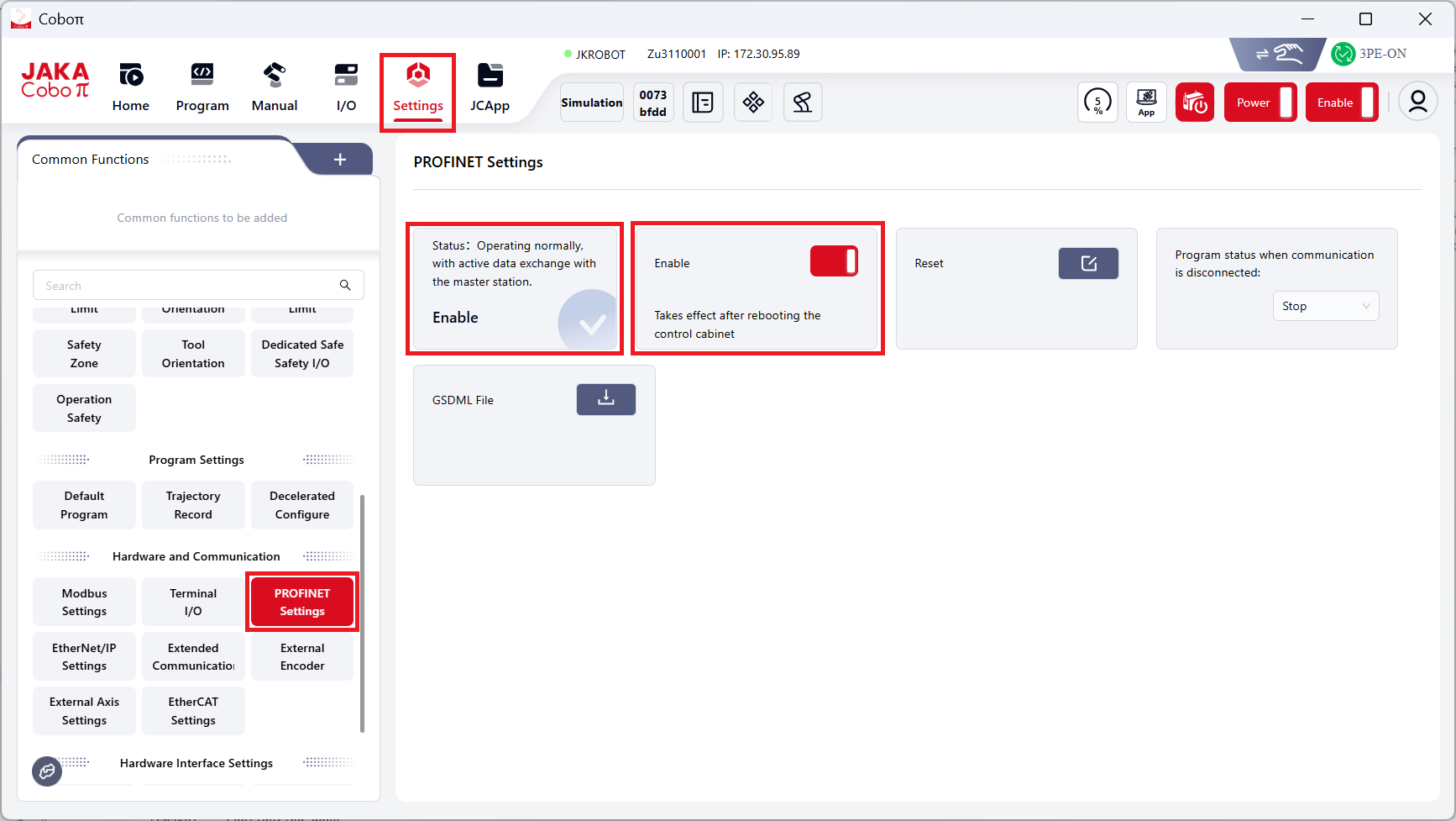
Restart the controller;
3.Switch the control source to external communication control.
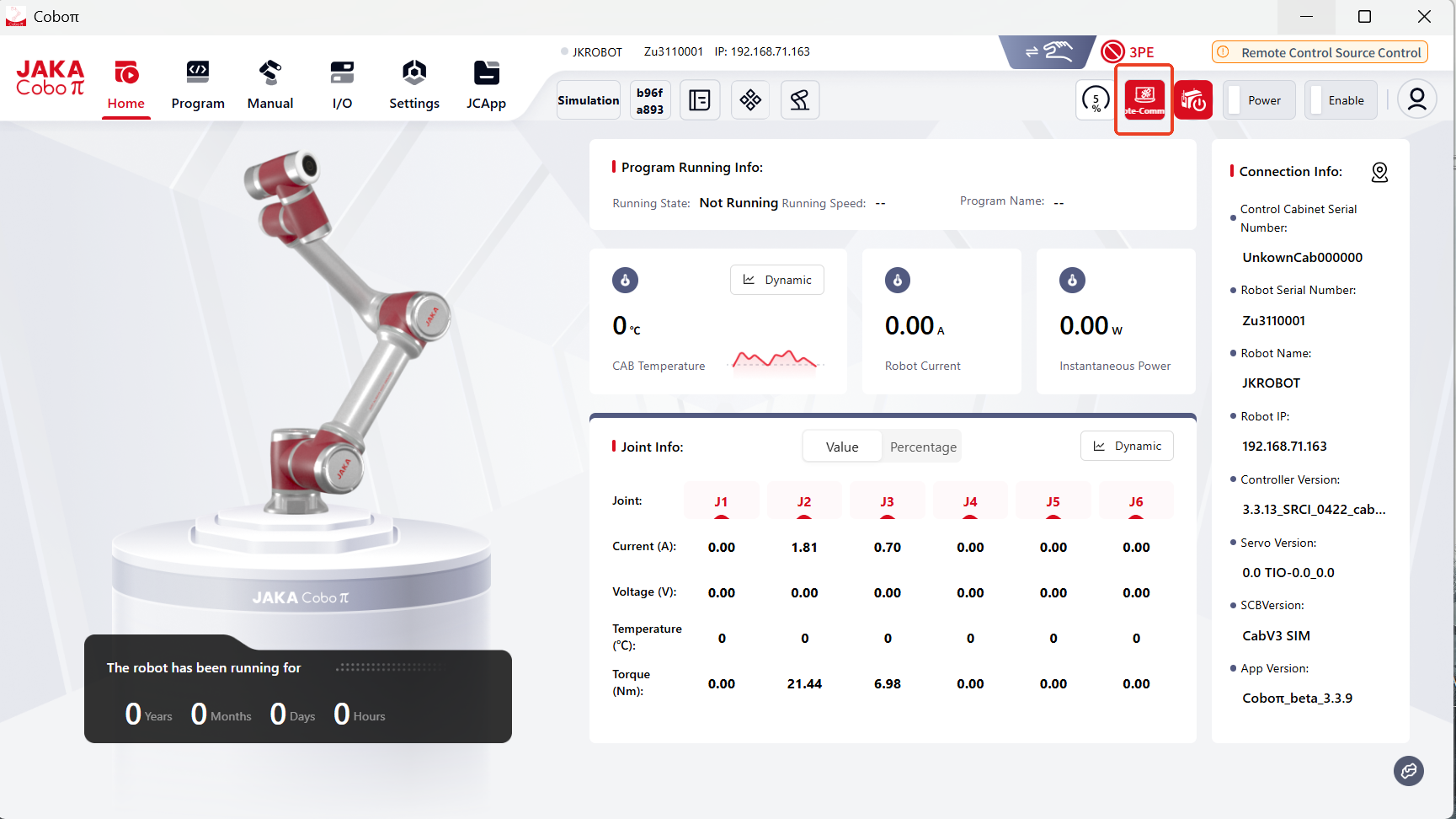
Prepare PLC
Initialize the SD card (when downloading programs from the Siemens PLC to a new SD card, users need to reset the SD card’s memory first. Otherwise the password might be needed).
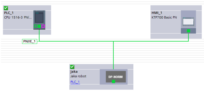
Import the correct JAKA GSDML file.
Configure PROFINET.
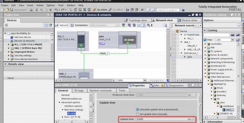
Set the IO cycle “Update time” for the PROFINET communication under the “Real time seetings” to 8ms (miliseconds).
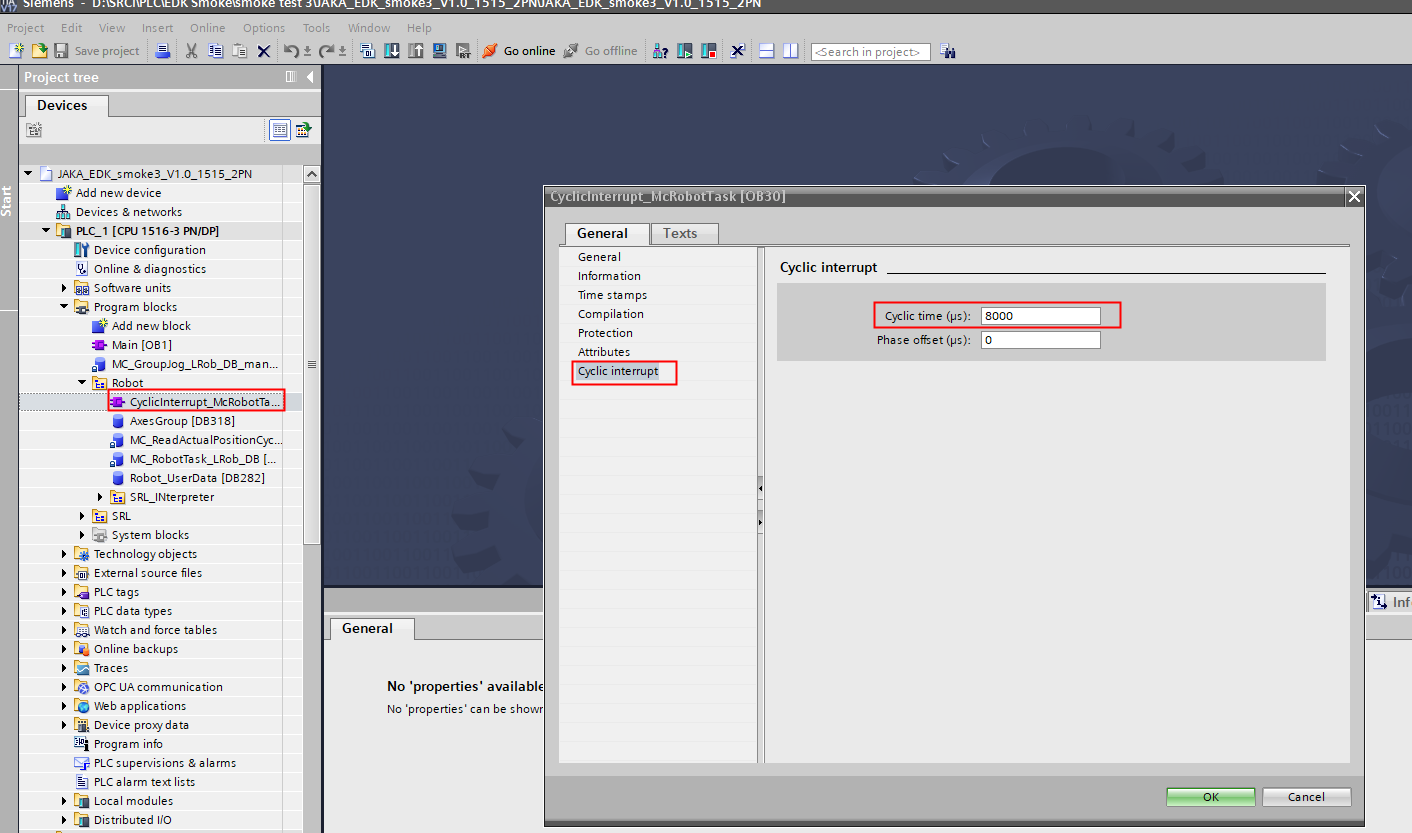
Set the Cyclic interrupt time to 8ms (miliseconds).
When configuring the SRCI data, it is essential to ensure the alignment of the data’s starting address with the starting address provided by RobTask. Failure to do so may result in initialization issues.
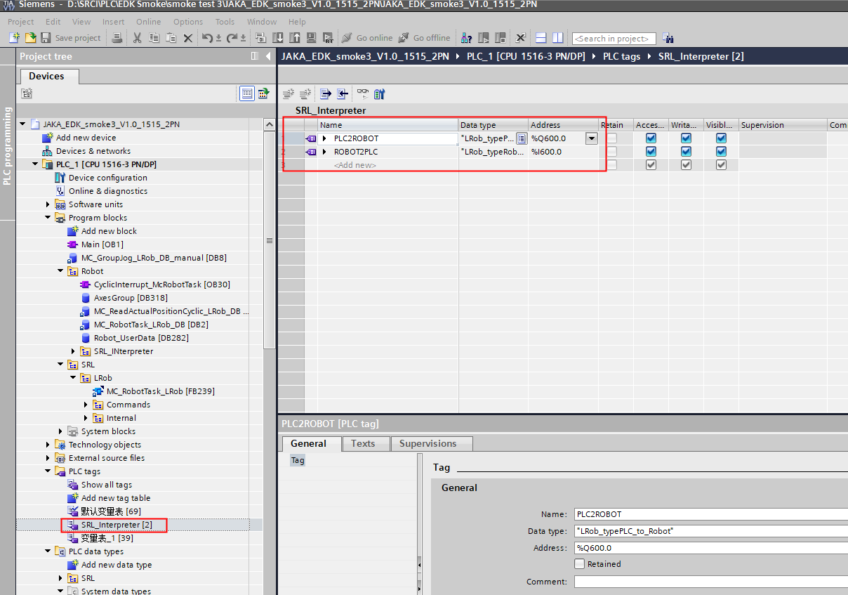
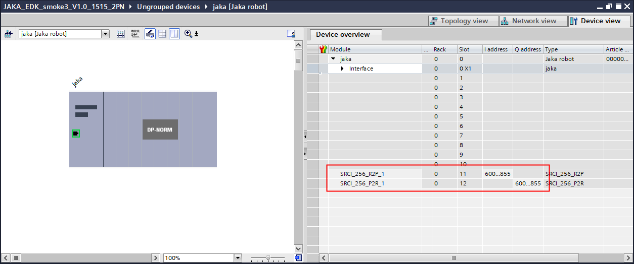
Troubleshooting
General debug steps:
Check if the version of the controller you are using.
Check if the control source is communication control.
Check if PROFINET is running properly(the PLC must use the correct JAKA GSDML)
Make sure that PLC PROFINET data is configured correctly.
If the above steps still don’t work, please contact JAKA technical support team(send an email to SRCI.Support@jaka.com, attaching Addon exported files).
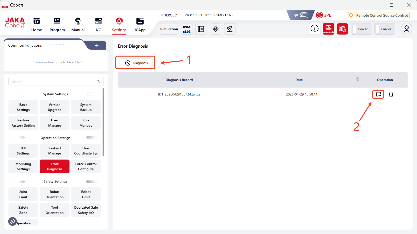
Follow the steps below to troubleshoot when SRCI communication fails:
Make sure that PROFINET communication between your JAKA robot and the PLC is estalished and functioning properly.
Make sure the PLC configuration is correct.
If the communication often disconnects, please check whether the switch meets PROFINET requirements; or connect the PLC directly to the control cabinet.
If PROFINET is connected and functoning properly, then the issue lyes with SRCI.
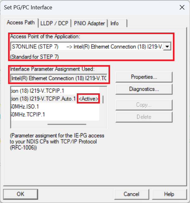
If an HMI simulation is required, please proceed with “Set PG/PC Interface” within your Windows Control Panel settings.
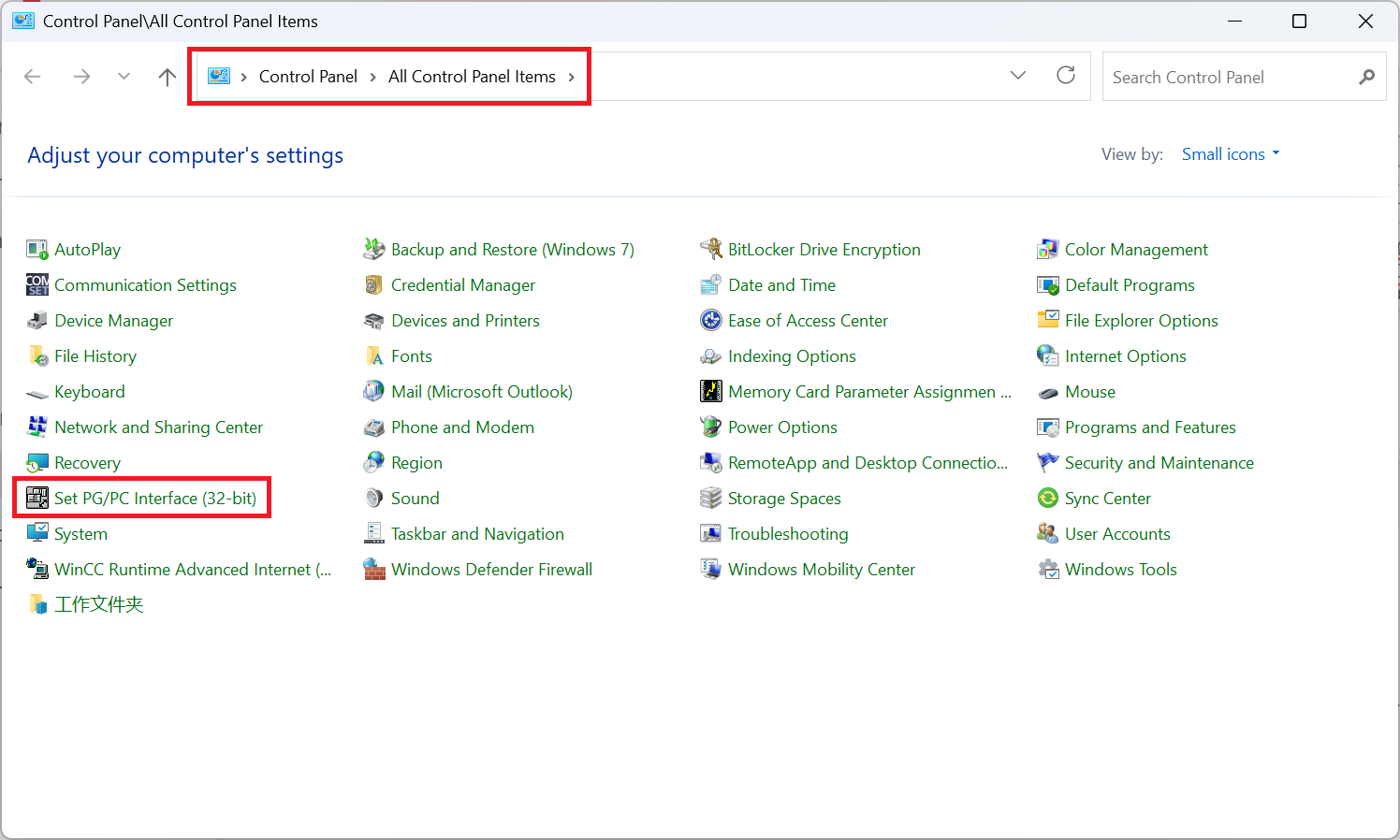
Under “Access Point of the Application”, select “S7ONLINE (STEP 7)”.
Under “Interface Parameter Assignment Used”, locate and select “your network adapter>.TCPIP.1”.
Your network adapter will be different depending on the WiFi NIC or wired ethernet NIC of the connection you are utilising.
To verify whether the desired selection has been saved and is in use, look for the tag Active next to the network adapter you selected.
Please contact Siemens for any further detailed information.
Debug steps when the robot fails to move:
Check the “overridespeed” parameter.
Check the velocity setting within “defaultDynamic” and “referenceDynamic”.
Check the velocity and acceleration parameters of the command.
Check if the robot is already in Interrupted status.
Appendix
JAKA Robot Arm SEW Description
Parameter |
Data Type |
Unit |
M/O |
Note |
|---|---|---|---|---|
Shoulder |
USINT |
|
M (support default 0) |
support 0-use config and 1-no change |
Elbow |
USINT |
|
M |
same as above |
Wrist |
USINT |
|
M |
same as above |
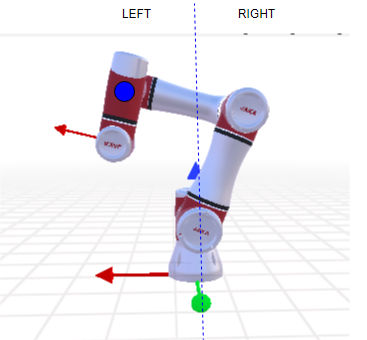
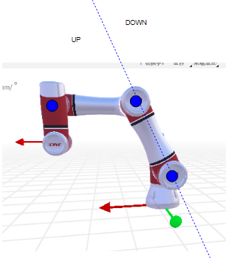
The configuration of collaborative robots generally differs from industrial robots, especially in that the 4-5-6 axes do not intersect at a single point. In other words, there is no traditional Wrist Center Point (WCP) as found in industrial robots. Typically, the intersection points of the 4-5 or 5-6 axes are used instead.
shoulder
elbow
wrist w = sin (axis5)
JAKA Blending:
Blending diagram: /
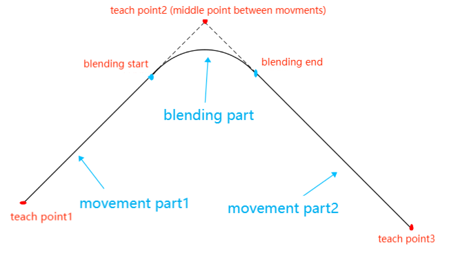
Supported situation for now:
joint to joint
joint to linear
linear to linear
linear to joint
To enable blending, make sure to set the parameters in usersetting.ini as below (No modifications are needed by default.):
MOVEJ_MOVEL_BLEND = 1
MOVEJ_MOVEJ_BLEND = 1
Supported BlendingMode:0(Exact Stop) and 4(MaxCornerDeviation)